

Page 1
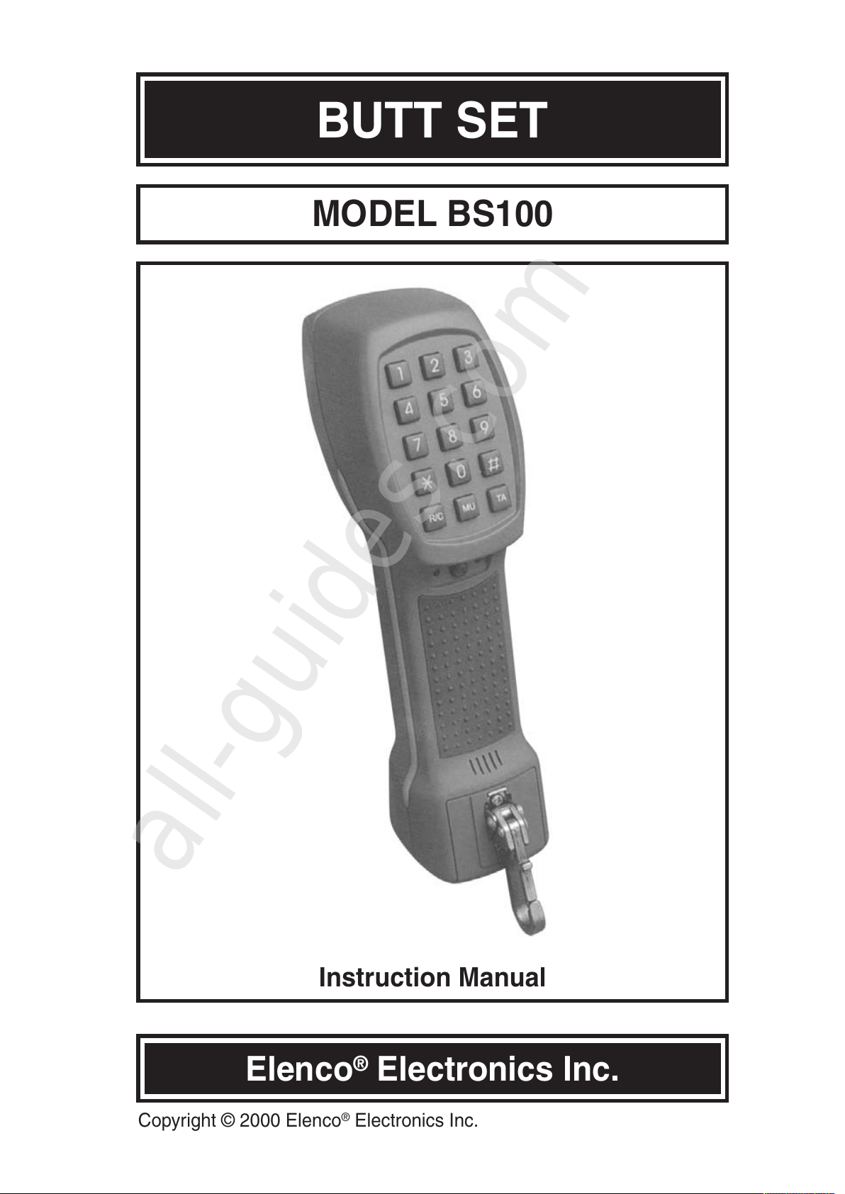
BUTT SET
MODEL BS100
Instruction Manual
Elenco®Electronics Inc.
Copyright © 2000 Elenco®Electronics Inc.
All manuals and user guides at all-guides.com
all-guides.com
Page 2

INTRODUCTION
-1-
The BS100 is designed for the installers, repair technicians, and other
authorized personnel for line testing and temporary communications. The
test set employs the latest in integrated circuit design to provide DTMF
(Touch Tone ) and dial pulse output. Different from other test sets, it
contains a mega ohm (MΩ) meter for testing insulation resistance and
telephone capacity. The repairman can independently find out line
conditions (faults) without the help of central office (CO) by measuring the
insulation resistance and telephone capacity.
The BS100 is made of high impact materials providing excellent insulating
properties. The rugged case is designed for rough handing and shocks
normally associated with field service.
FEATURES
1. Monitor (Data safe) function
2. Talk function
3. Tone/Pulse dialing
4. Last number redial in both tone and pulse modes
5. Hook and Flash function
6. Terminating function
7. Speaker phone function
8. Polarity Checking
9. Mute function
10. Waterproof
11. Piercing pin and angled bed nails cord (ABN)
12. Insulation resistance measurement.
13. Earth-state
14. Line-cut (open)
15. Line-short
16. Telephone capacity
All manuals and user guides at all-guides.com
Page 3
-2-
SPECIFICATIONS
ELECTRICAL
Loop Resistance less than 300Ω (talk mode)
Monitor Impedance greater than 100kΩ
ROTARY DIAL OUTPUT
Pulsing Rate 100pps +/– 0.8%
Make Rate 33 +/– 3%
Minimum Pose 600ms over
DTMF OUTPUT
Frequency Deviation +/– 1.8%
Level Deviation High –8dBm, Low –6dBm +/–0.8%
Return Loss 2dBm
Redial 32 digits
Insulation Resistance 0.1- 10MΩ (DC 180V)
Power Source DC 9V
PHYSICAL
Length 2.71” (69mm)
Width 10.08” (256mm)
Height 3.35” (85mm)
Weight 20 ounces (560g)
BATTERY REPLACEMENT
1. Remove the two screws from the battery compartment
2. Remove the cover and the clear rubber gasket
3. Replace the battery with an alkaline or lithium 9V battery.(polarity
indicated on cover)
4. Install the gasket, cover and screws.
MAINTENANCE
All manuals and user guides at all-guides.com
Page 4

-3-
PHYSICAL DESCRIPTION (See Figure 1)
1. Receiver
2. Mega Ohm (MΩΩ) meter
3
. Company logo
4. TONE/PULSE: On/Off switch for pulse or tone.
5. CALL: On/Off switch. Off position for MΩ insulation meter and On for
subscriber calling with the METER/CALL switch.
6. HOOK: On/Off switch.
7. Microphone
8. SP: Speakerphone switch.
9. MON: On/Off switch for line monitoring without data loss.
10. TEST/CALL: Button for Insulation Resistance measurement and
subscriber calling.
11. Dial Keypad: The recessed 16-button keypad is housed in the
receiver end of the housing. The recessed design provides physical
protection to the keyboard and prevents accidental button operation.
12. Polarity LED’s
13. Polarity LED’s
14. P: Polarity button.
15. Speaker phone output
16. Cordset: The cord set with one red and one black conductor. Each
conductor is fitted with an alligator clip, offset 20 degrees, with piercing
pin and angled bed nails cord (ABN).
17. Belt clip: A spring-loaded belt clip secures to a belt loop or D-ring.
18. Cord line hanger
19. Non-Slip Pad: The form and non-slip pad on back of the handgrip
frees up both hands while the Butt set rest on the shoulder.
20. Battery cover: Compartment for one 9V battery.
All manuals and user guides at all-guides.com
Page 5

-4-
Figure 1
FRONT
BACK
All manuals and user guides at all-guides.com
Page 6

-5-
OPERATION INSTRUCTIONS
PLACING A NORMAL CALL
A calling signal is sent to the subscriber's telephone causing it to ring.
1. Set to data safe mode by pressing the MON (9) switch.
2. Connect the alligator clips to L1 and L2 of subscriber side.
3. Listen for a clear line (no data).
4. Release the data safe mode by pressing MON switch again. A dial tone
should be heard.
5. Select the type of dial signaling required, touch-tone or dial pulse, with
the TONE/PULSE switch. Note that the phone will be in the last type
selected.
6. Enter the desired number on the keypad. For touch-tone signaling,
tones associated with the respective key will be generated. Rotary dial
signaling digits will automatically be pulsed out at the correct rate. To
terminate the call, press the HOOK button.
SUBSCRIBER CALLING
A calling signal is sent to the subscriber's telephone causing it to ring. You
can also talk with the subscriber. This function is useful when the 48V
power is not supplied from the telephone office
1. Connect the alligator clips to L1 and L2 of subscriber side.
2. Push the CALL (5) button and the Led will illuminate.
3. Push the TEST/CALL (10) button to make subscriber's phone ring. To
conserve the battery life, press button several times.
HOOK FUNCTION
This switch establishes a 0N-HOOK or OFF-HOOK condition to the line.
1. Connect the alligator clips to L1 and L2 of subscriber side.
2. The HOOK LED is off indicating an OFF-HOOK condition and dial tone
is present.
3. Pressing the HOOK (6) button, the Led will illuminate and the unit is
ON-HOOK. Incoming call will cause the bell to ring.
TONE/PULSE
This position is used to select the between the two dial modes. The PULSE
position selects rotary style dial pulses signaling. The TONE position
selects the DTMF signaling.
1. Connect the alligator clips to L1 and L2 of subscriber side.
2. Press the TONE/PULSE (4) to select the type of dial signaling required,
touch-tone or dial pulse. Note that the phone will be in the last type
selected.
All manuals and user guides at all-guides.com
all-guides.com
Page 7

-6-
OPERATION INSTRUCTIONS (CON’T)
REDIAL (RD)
Will redial the last number entered.
1. Press the FS button for a new dial tone.
2. Press the RD button to redial the last number entered. Up to 32 digits
can be redialed.
MUTE (MU)
When pressed, the transmitter is muted and the side tone is eliminated.
1. Press and hold the MU to mute, release to talk.
FLASH (FS)
The tester produces a line break (hook flash). It is typically used for
register recall or redialing.
1. Press the FS button for a new dial tone.
SPEAKER PHONE FUNCTION (SP)
This allows you to listen handsfree
1. Connect the alligator clips to L1 and L2 of subscriber side.
2. Presses the SP (8) button activate the speakerphone.
3. Pressing the SP (8) button again will turn off speakerphone function.
MONITOR FUNCTION (MON)
The monitor position provide a high impedance (over 100kΩ) coupling to
the line without disrupting conversation, data or signaling.
1. Press the MON (8) button the LED will illuminate. The unit is in a high
impedance condition.
2. Connect the alligator clips to L1 and L2 of subscriber side.
3. Pressing the MON button again, the LED turns off and the high
impedance condition is removed.
POLARITY INDICATOR
The line polarity is checked and indicated on the red or green LED’s.
1. Connect the alligator clips to L1 and L2 of subscriber side.
2. Press the P (14) and the two LED’s indicate the polarity as follows.
Green LED ‘ON’ The line with red alligator clip is TIP (+).
The line with black alligator clip is RING (–).
Red LED ‘ON’ The line with red alligator clip is RING (–).
The line with black alligator clip is TIP (+).
All manuals and user guides at all-guides.com
Page 8

Elenco®Electronics Inc.
150 Carpenter Ave. Wheeling, IL 60090 USA
Website: www.elenco.com
Made in South Korea
INSULATION RESISTANCE & CAPACITY MEASUREMENT
1. Connect the alligator clips to L1 and L2 of subscriber side.
2. Push the TEST/CALL (10) button.
3. The insulation resistance will be displayed on the 'Mega Ohm meter,
when the TEST/CALL button is pressed.
Generally, there are two conditions:
Normal condition (good insulation between L1 and L2)
The meter scale goes to 0.2Ω generally and then back. This is caused
by the capacity of the connected subscriber's telephone or the line and
terminal.
Abnormal condition (bad insulation between L1 and L2)
The meter scale goes up to a low value (below 1MΩ) and stays there.
This indicates a faulty circuit on L1 and L2.
Note - The meter will not move if the line is an open circuit.
BATTERY CHECK
Indicates if 9-volt battery requires replacement.
1. Connect the two alligator leads together.
2. Press the TEST/CALL (10) button. A good battery is indicated if the
needle is in the BT section of the meter. If the needle is below, the
battery should be replaced.
TWO YEAR WARRANTY
All Elenco®models are guaranteed for two full years on all parts
and service. For the first 3 months, your butt set is covered at
absolutely no charge. For the remaining 21 months, a nominal
service charge is required to cover shipping and handling.
When returning merchandise for repair, please include proof of
purchase, a brief letter of explanation of problem, and sufficient
packing material. Before returning any merchandise please call
our service department at (847) 541-3800 to obtain a return
authorization number (RMA).
Service Department
All manuals and user guides at all-guides.com
 Loading...