

Page 1
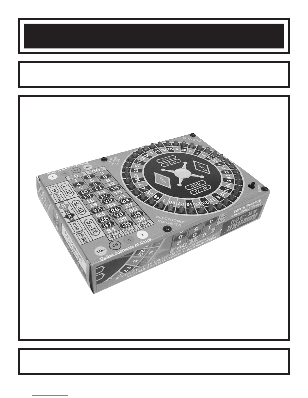
ELECTRONIC ROULETTE KIT
MODEL AK-300
Instruction & Assembly Manual
Elenco®Electronics, Inc.
ight © 2005, 1997 b
yr
Cop
t of this book shall be reproduced b
No par
y Elenco
®
Electronics
y means;
y an
, Inc.
electronic
ights reser
All r
, photocopying, or otherwise without written permission from the publisher.
ved. Revised 2005 REV-D 753031
Page 2

PARTS LIST
If you are a student, and any parts are missing or damaged, please see instructor or bookstore.
I
f you purchased this roulette kit from a distributor, catalog, etc., please contact Elenco®E
(address/phone/e-mail is at the back of this manual) for additional assistance, if needed. DO NOT contact your
place of purchase as they will not be able to help you.
RESISTORS
Qty. Symbol Value Color Code Part #
1 R22 1kΩ 5% 1/4W brown-black-red-gold 141000
4 R1 - R4 1.2kΩ 5% 1/4W brown-red-red-gold 141200
1 R19 1.5kΩ 5% 1/4W brown-green-red-gold 141500
5 R5 - R9 10kΩ 5% 1/4W brown-black-orange-gold 151000
2 R15, R16 20kΩ 5% 1/4W red-black-orange-gold 152000
1 R13 47kΩ 5% 1/4W yellow-violet-orange-gold 154700
1 R17 56kΩ 5% 1/4W green-blue-orange-gold 155600
2 R11, R20 100kΩ 5% 1/4W brown-black-yellow-gold 161000
1 R24 270kΩ 5% 1/4W red-violet-yellow-gold 162700
1 R14 330kΩ 5% 1/4W orange-orange-yellow-gold 163300
1 R10 820kΩ 5% 1/4W gray-red-yellow-gold 168200
1 R23 1.8MΩ 5% 1/4W brown-gray-green-gold 171800
1 R12 2.2MΩ 5% 1/4W red-red-green-gold 172200
1 R18 3.3MΩ 5% 1/4W orange-orange-green-gold 173300
1 R21 4.7MΩ 5% 1/4W yellow-violet-green-gold 174700
lectronics
CAPACITORS
Qty. Symbol Value Description Part #
1 C4 .001µF Discap (102) 231036
1 C2 .0033
1 C1 .02µF or .022µF Discap (203 or 223) 242010
1 C5 .47µF Electrolytic (Lytic) 254747
2 C3, C6
2 C7, C8 100µF Electrolytic (Lytic) 281044
µF Mylar (332) 233317
1
µF Electrolytic (L
ytic) 261047
SEMICONDUCTORS
Qty. Symbol Value
2 D41, D43 1N4001 Diode 314001
3 D39, D40, D42 1N4148 Diode 314148
7 Q1 - Q4, Q7 - Q9 2N3904 Transistor 323904
2 Q5, Q6 2N3906 Transistor 323906
U1, U3 4017 Integrated Circuit 334017
2
1 U2 4069 Integrated Circuit 334069
36 D1 - D36 LED Red 350002
D37, D38 LED Green 350010
2
Description Part #
MISCELLANEOUS
Symbol Description Part #
Symbol Description Part #
.
Qty
1 PC Board 517100
1 S1 Push Button Switch 540101
BT Battery Holder 9V 590096
1
1 BZ1 Buzzer Piezoelectric 595201
4 Plastic Spacer 624010
3
8 Screw 4-40 x 1/4” Black 641433
3 Nut 2-56 Hex 644201
Screw 2-56 x 5/16” 641231
.
Qty
4 Flat Washer Black 645404
3 Flat Washer White 645600
U2 14-pin Socket 664014
1
2 U1, U3 16-pin Socket 664016
1 Paper Clip 680018
1
1 40” Wire 22ga. Bare 845000
1 Solder Tube 9ST4A
4” Wire 22ga. Black Solid
814120
**** SAVE THE BOX THAT THIS KIT CAME IN. IT WILL BE USED ON PAGE 10. ****
-1-
Page 3
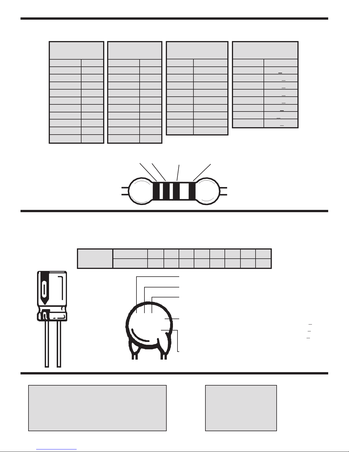
IDENTIFYING RESISTOR VALUES
Use the following information as a guide in properly identifying the value of resistors.
BAND 1
1st Digit
Color Digit
Black 0
Brown 1
Red 2
Orange 3
Yellow 4
Green 5
Blue 6
Violet 7
Gray 8
White 9
BAND 2
2nd Digit
Color Digit
Black 0
Brown 1
Red 2
Orange 3
Yellow 4
Green 5
Blue 6
Violet 7
Gray 8
White 9
2 Multiplier Tolerance
1
Multiplier
Color Multiplier
Black 1
Brown 10
Red 100
Orange 1,000
Yellow 10,000
Green 100,000
Blue 1,000,000
Silver 0.01
Gold 0.1
BANDS
Resistance
Tolerance
Color Tolerance
Silver +
Gold +5%
Brown +1%
Red +2%
Orange +3%
Green +
Blue +.25%
Violet +.1%
10%
.5%
IDENTIFYING CAPACITOR VALUES
Capacitors will be identified by their capacitance value in pF (picofarads), nF (nanofarads), or µF (microfarads). Most
capacitors will have their actual value printed on them. Some capacitors may have their value printed in the following
manner. The maximum operating voltage may also be printed on the capacitor.
Multiplier
10µF 16V
For the No. 01234589
Multiply By 1 10 100 1k 10k 100k .01 0.1
Note: The letter “R” may be used at times
to signify a decimal point; as in 3R3 = 3.3
The letter M indicates a toler
The letter K indicates a tolerance of +
The letter J indicates a toler
103K
100V
First Digit
Second Digit
Multiplier
olerance
T
Maximum Working Voltage
ance of +20%
10%
ance of +5%
The value is 10 x 1,000 = 10,000pF or .01µF 100V
METRIC UNITS AND CONVERSIONS
viation Means Multiply Unit By Or
Abbre
p Pico .000000000001 10
n
µ micro .000001 10
m milli .001 10
– unit 1 10
k kilo 1,000 10
M
nano
mega
.000000001
1,000,000
10
10
1,000 pico units
-12
-9
-6
-3
0
3
6
1.
2. 1,000 nano units = 1 micro unit
3. 1,000 micro units= 1 milli unit
1,000 milli units
4.
5. 1,000 units = 1 kilo unit
6. 1,000 kilo units= 1 mega unit
= 1 nano unit
= 1 unit
-2-
Page 4

INTRODUCTION
Electronic Roulette (roo-let) replaces the ivory ball
with a circuit of flashing light emitting diodes (LED’s).
Red LED’s are arranged in a circle next to a black or
red number and two green LED’s are positioned next
to “0” and “00”. When the switch is pushed, the LED’s
light one after another, in a sequence that represents
the movement of the ivory ball. The number next to
THEORY OF OPERATION
THE BLOCK DIAGRAM
The function of many of the circuits will be presented
in the form of an analogy (similar operation, but
easier-to-understand system). In this manner, the
operation of a circuit can be explained without the
use of mathematics and equations.
Figure 1 shows a Block Diagram of the Electronic
Roulette circuits. The Timer circuit is used to turn all
the other circuits on and off. The Pulse Generator
es pulses that create the sound and force the
mak
ring counter to move the position of the lit LED. The
Sound Circuit generates the sound of a bouncing
y ball, and a warning tone a f
or
iv
power down. The Ring Counter lights each LED in a
circular sequence. The LED’s represent the position
Timer
ory ball.
Pulse
Generator
of the iv
ew seconds before
Ring
Counter
Sound
Circuit
LED’s
the lit LED when movement stops is the winning
number. During movement, the sound of a bouncing
ball is generated. If the switch is not pressed again,
the circuits will automatically turn off, to conserve the
battery power. A constant tone will alert you to check
your number before automatic shut down.
THE TIMER
When S1, the start button, is pushed, capacitor C7
(Figure 2, Schematic Diagram) is charged to the
battery voltage. This is similar to flipping the “Timer
Glass” shown in Figure 2a to produce the condition
shown in Figure 2b. Just as the sand runs down
holding the lever arm up (Figure 2b), the charges in
th capacitor C7 forces transistors Q6, Q8, and Q9 on.
As long as the lever arm is up in Figure 2b, the other
circuits are po
switch X1. At first, due to the weight of the sand
(similar to capacitor C7 being fully charged), the
contact C2 will open and remain open.
the sand totally runs out (capacitor C7 has lost most
of its charge), the contact C2 will close, as shown in
Figure 2c
contact C1 is about to open and turn all the power
off, including the power to the warning circuit.
Eventually all the sand r
(capacitor C7 has discharged) and the power is
turned off (Figure 2a). To make the timer stay on
longer
, you could get a bigger “Timer Glass”
capacitor for C7) that holds more sand and replace
the smaller one.
wered through the contact C1 on
, and sound an alarm to war
n you that the
uns out of the “Timer Glass”
Right bef
(larger
ore
Figure 1
C1
A
B
C
Sand
Sand
C2
C1
C2
C1
C2
Figure 2
wer for all circuits
o
P
Battery
Warning Circuit
Switch X1
ower for all circuits
P
Battery
Warning Circuit
Switch X1
Power for all circuits
y
Batter
arning Circuit
W
Switch X1
-3-
9V
Battery
BT1
To Warning
Circuit
100
Schematic Diagram
Q6
2N3906
R22
µF
100
S1
1kΩ
R21
4.7M
Ω
C7
µF
R23
1.8M
Ω
C8
C3
1
Q9
2N3904
ower for
P
All Circuits
µF
Q8
2N3904
Page 5
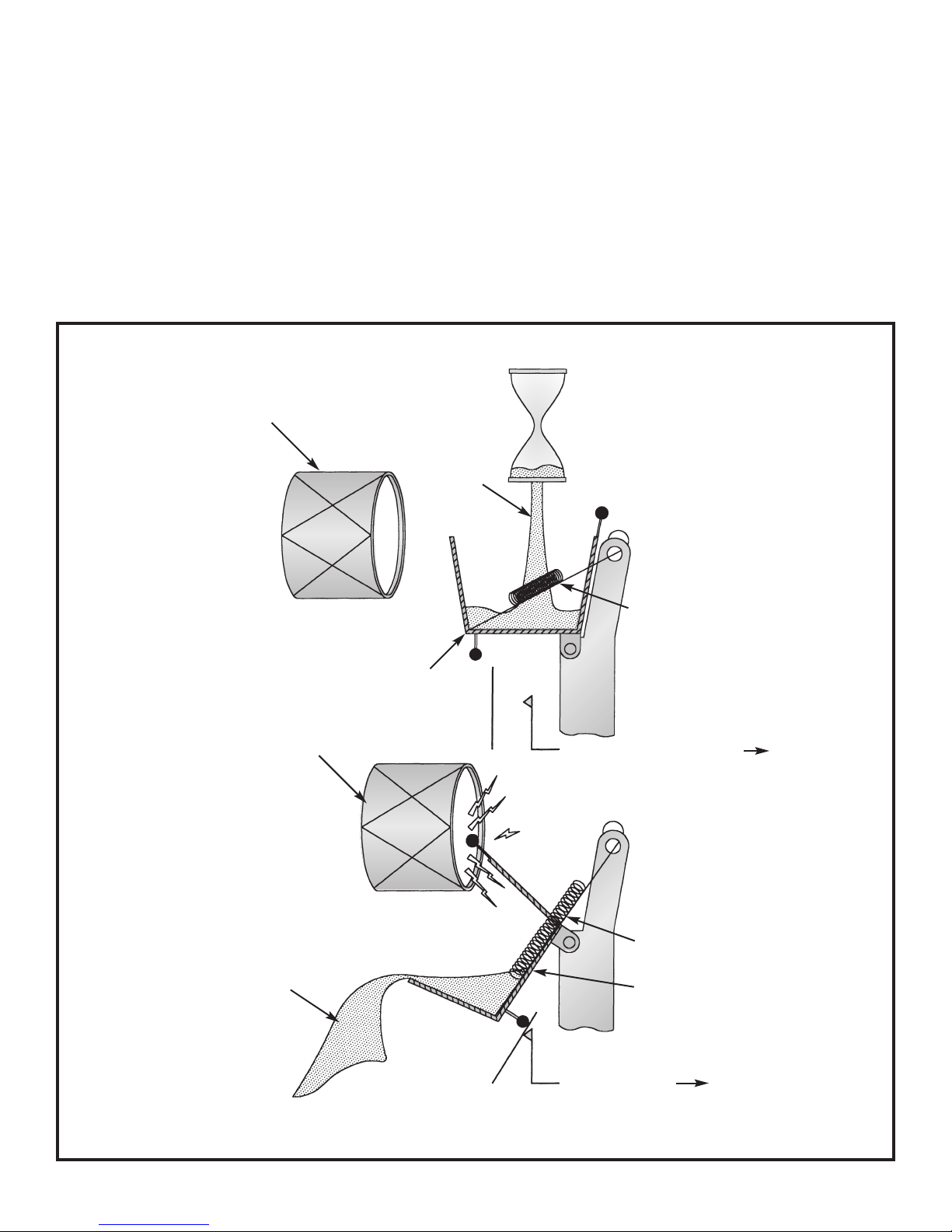
THE PULSE GENERATOR
A
ssume that part of the sand from the “Timer Glass” in
Figure 2 is poured into a bucket as shown in Figure 3a.
When the bucket has enough sand, it will flip and
dump as shown in Figure 3b. Each time it flips, it
closes switch X2, sending the battery voltage to the
Ring Counter and it strikes the “Drum” producing a
sound. The bucket in Figures 3a & 3b represents
capacitor C6 in the schematic diagram on page 12.
Capacitor C6 charges (charging = filling the bucket
with sand) through resistor R20 and discharges
(dumping the sand) through resistor R19 and diode
A
Drum for sound
Sand
D
41. Each time the sand changes buckets, a pulse
is sent to the Ring Counter and to the Sound Circuit.
When the bucket is empty, the spring returns it to the
filling position shown in Figure 3a. The sand going
into the bucket will flow slower as the “Timer Glass”
in Figure 2 runs out of sand. It will take longer and
longer to fill the bucket as the sand runs out. This
produces more space between the pulses sent to the
ring counter and has the effect of slowing down the
rotation of the lights, similar to the ivory ball slowing
down on a roulette wheel.
B
Drum for sound
Sand
Bucket
X2
Battery
X2
Spring
Electrical Poles — 0 Volts To Ring Counter
Spring
ket
Buc
y
Batter
Battery Voltage To Ring Counter
Figure 3 Pulse Generator
-4-
Page 6

THE SOUND CIRCUIT
I
n the sound generator circuit, a 500Hz oscillator is
a
lways running. This oscillator is represented by the
spinning wheel in Figure 4a. No sound is heard
because the spinning wheel is not hitting the drum.
When the bucket in Figure 3 dumps sand, the lever
arm pushes the spinning wheel against the stop and
the small balls on the spinning wheel hit the drum,
producing a high frequency sound (Figure 4b). The
lever arm turns the sound on and represents
transistor Q7 in Figure 4c. When the lever arm is
removed, the spring pulls the spinning wheel away
from the drum and the sound stops. In much the
same way, transistor Q7 turns off shortly after a pulse
is received. This action stops electrical current from
flowing through the piezoelectric buzzer (drum),
eliminating the sound. Just before power down,
transistor Q7 is turned on and kept on to produce the
warning sound.
A
Spinning Wheel
Bucket Lever Arm
B
Spinning Wheel
Bucket Lever Arm
Drum
Stop
Spring
Drum
Stop
THE RING COUNTER
In it’s simplest form, the ring counter can be
compared to a circle of buckets with only one bucket
filled with sand as shown in Figure 5a. Because of
the weight of the sand, the filled bucket hangs lower
than all of the rest. When a pulse is received from
the pulse generator circuit, it pushes the sand to the
ucket as shown in Figure 5b. This process
xt b
ne
continues passing the sand from bucket to bucket in
a circle, until no more pulses are received from the
pulse gener
Ring of Buckets
ator.
AB
Bucket filled with
sand hangs lo
than all of the rest.
wer
C
Piezoelectric
Buzzer
From Pulse
Generator
es sand
Pulse mo
to the next bucket.
v
BZ1
D2
1N4148
R16
20kΩ
C5
.47µF
C2
.0033µF
R11
100kΩ
R
56kΩ
Light Off
Empty Bucket
U2D
4
Q7
2N3904
17
Spring
069
Power
500Hz Oscillator
R14
330kΩ
U
098
1
4069
Turns Sound On
2E
11
From Ring
Counter
R134
47kΩ
R12
2.2MΩ
Figure 4
Sound Circuit
Light On
Power
Buc
Sand
et with
k
Pulse Plate
Moves up when pushed.
THE LED’s
The Light Emitting Diodes (LED’s) are no more than
If they are arranged in a circle
small electronic lights
and connected to a ring counter, they can be used to
represent the ivory ball position on the roulette
wheel. When the buckets filled with sand stretch out
the springs in Figure 5, they could also close a switch
.
Figure 5 Figure 6
as shown in Figure 6. This would light the next light
in the circle and produce the eff
ect of a ball spinning
around the roulette wheel. As the pulses get further
and further apart, the electronic ball will appear to
slow down and eventually stop.
-5-
Page 7

CONSTRUCTION
Introduction
The most important factor in assembling your AK-300 Electronic Roulette Kit is good soldering techniques.
Using the proper soldering iron is of prime importance. A small pencil type soldering iron of 25 - 40 watts is
recommended. The tip of the iron must be kept clean at all times and well tinned.
Safety Procedures
• Wear eye protection when soldering.
Locate soldering iron in an area where you do not have to go around it or reach over it.
•
• Do not hold solder in your mouth. Solder contains lead and is a toxic substance. Wash your hands
thoroughly after handling solder.
• Be sure that there is adequate ventilation present.
Assemble Components
In all of the following assembly steps, the components must be installed on the top side of the PC board unless
otherwise indicated. The top legend shows where each component goes. The leads pass through the
corresponding holes in the board and are soldered on the foil side.
Use only rosin core solder of 63/37 alloy.
DO NOT USE ACID CORE SOLDER!
What Good Soldering Looks Like
A good solder connection should be bright, shiny,
smooth, and uniformly flowed over all surfaces.
1. Solder all components from
the copper foil side only.
Push the soldering iron tip
against both the lead and
the circuit board foil.
2. Apply a small amount of
solder to the iron tip. This
allows the heat to leave the
iron and onto the f
Immediately apply solder to
the opposite side of the
connection, away from the
iron. Allow the heated
component and the circuit
oil to melt the solder.
f
Allow the solder to flo
3.
around the connection.
Then, remove the solder
and the iron and let the
connection cool.
solder should have flowed
smoothly and not lump
around the wire lead.
4.
Here is what a good solder
connection looks like.
oil.
The
Component Lead
Foil
Solder
Foil
w
Solder
F
oil
Soldering Iron
Circuit Board
Soldering Iron
Soldering Iron
Types of Poor Soldering Connections
1. Insufficient heat - the
solder will not flow onto the
lead as shown.
2. Insufficient solder - let the
solder flow over the
connection until it is
vered. Use just enough
co
solder to co
connection.
3. Excessive solder - could
make connections that you
did not intend to between
adjacent foil areas or
minals.
ter
4. Solder bridges - occur
when solder runs between
circuit paths and creates a
short circuit. This is usually
caused by using too much
solder. To correct this,
simply dr
iron across the solder
bridge as shown.
ag y
ver the
our solder
ing
Rosin
Soldering iron positioned
incorrectly.
Solder
Component Lead
Solder
Solder
Foil
Gap
ing Iron
Dr
ag
-6-
Page 8

ASSEMBLE COMPONENTS TO THE PC BOARD
I
dentify and install the following parts as shown. After soldering each part, place a check in the box provided.
S
pace the LED’s with a paper clip (use size shown below) so that they are 1/4” off of the PC board.
U1 - 16-pin Socket
U1 - 4017 Integrated Circuit
(see Figure B)
R1 - 1.2kΩ 5% 1/4W Resistor
R2 - 1.2kΩ 5% 1/4W Resistor
R3 - 1.2kΩ 5% 1/4W Resistor
R4 - 1.2kΩ 5% 1/4W Resistor
(brown-red-red-gold)
Q1 - 2N3904 Transistor
Q2 - 2N3904 Transistor
Q3 - 2N3904 Transistor
Q4 - 2N3904 Transistor
(see Figure C)
R5 - 10kΩ 5% 1/4W Resistor
R6 - 10kΩ 5% 1/4W Resistor
R7 - 10kΩ 5% 1/4W Resistor
R8 - 10kΩ 5% 1/4W Resistor
(brown-black-orange-gold)
Q5 - 2N3906 Transistor
(see Figure C)
U3 - 16-pin Socket
U3 - 4017 Integrated Circuit
(see Figure B)
Note: Install the
jumper wires first.
1/4”
LED Spacer (Actual Size)
Install jumper wires J1 – J40
using bare wire.
J1 – J40 - Jumper Wires
(see Figure G)
C4 - .001µF (102) Capacitor
C5 - .47µF Electrolytic
(see Figure D)
R10 - 820kΩ 5% 1/4W Resistor
(gray-red-yellow-gold)
R11 - 100kΩ 5% 1/4W Resistor
wn-black-yellow-gold)
(bro
D38 - LED Green
(see Figure A)
Q7 - 2N3904 Transistor
(see Figure C)
R16 - 20kΩ 5% 1/4W Resistor
(red-black-orange-gold)
C6 - 1µF Electrolytic
(see Figure D)
C7 - 100µF Electrolytic
C8 - 100µF Electrolytic
(see Figure D)
Figure A
Mount the LED onto the PC
with the flat side of the LED in the
same direction as marked on the
PC board. Space the LED’s with a
paper clip. Make sure that it is 1/4”.
Flat
board
1/4”
Figure B
et onto the PC board
Socket
k
IC
Notch
Mount the IC soc
with the notch in the same direction as
marked on the PC board. Then, mount
the IC onto the socket with the notches
in the same direction.
PC Board
Figure C
Mount the tr
flat side in the same direction
as marked on the PC board.
Flat
ansistor with the
.35”
max.
-7-
Page 9

ASSEMBLE COMPONENTS TO THE PC BOARD
I
dentify and install the following parts as shown. After soldering each part, place a check in the box provided.
S
pace the LED’s with a paper clip (use size shown below) so that they are 1/4” off of the PC board.
C1 -
.02µF or .022µF
(203 or 223) Discap
1/4”
LED Spacer (Actual Size)
R12 - 2.2MΩ 5% 1/4W Resistor
(red-red-green-gold)
R9 - 10kΩ 5% 1/4W Resistor
(brown-black-orange-gold)
R13 - 47kΩ 5% 1/4W Resistor
(yellow-violet-orange-gold)
R14 - 330kΩ 5% 1/4W Resistor
(orange-orange-yellow-gold)
D37 - LED Green
(see Figure A)
C2 - .0033µF (332) Mylar Cap.
(see Figure F)
D40 - 1N4148 Diode
(see Figure E)
Figure D
.
ity
e polar
Electrolytic capacitors ha
sure to mount them with the negativ
lead (marked on the side) in the correct
hole. Bend the capacitor 90
below.
v
O
as shown
Polarity Marking
e (–)
Figure E
Be
Mount the diode with the band
in the same direction as marked
on the PC board.
Band
Figure F
Mount the m
PC board with 0.35”
below.
ylar capacitor at a 45
O
.35”
max.
angle to the
maximum height as shown
C3 - 1µF Electrolytic
(see Figure D)
U2 - 14-pin Socket
U2 - 4069 Integrated Circuit
(see Figure B)
D39 - 1N4148 Diode
(see Figure E)
D41 - 1N4001 Diode
(see Figure E)
R19 - 1.5kΩ 5% 1/4W Resistor
wn-green-red-gold)
(bro
R23 - 1.8MΩ 5% 1/4W Resistor
(brown-gray-green-gold)
R20 - 100kΩ 5% 1/4W Resistor
(brown-black-yellow-gold)
R22 - 1kΩ 5% 1/4W Resistor
(brown-black-red-gold)
D43 - 1N4001 Diode
(see Figure E)
Figure G
m a jumper wire.
Use the bare wire supplied to f
Bend the wire to the correct length and mount it to
the PC board.
or
PC Board Mar
king
-8-
Page 10

ASSEMBLE COMPONENTS TO THE PC BOARD
I
dentify and install the following parts as shown. After soldering each part, place a check in the box provided.
1/4”
LED Spacer (Actual Size)
D1 – D36 - LED Red (be sure to note
the flat side when installing).
see Figure A)
(
R15 - 20kΩ 5% 1/4W Resistor
(red-black-orange-gold)
R17 - 56kΩ 5% 1/4W Resistor
(green-blue-orange-gold)
D42 - 1N4148 Diode
(see Figure E)
R24 - 270kΩ 5% 1/4W Resistor
(red-violet-yellow-gold)
R18 - 3.3MΩ 5% 1/4W Resistor
(orange-orange-green-gold)
R21 - 4.7MΩ 5% 1/4W Resistor
(yellow-violet-green-gold)
Q9 - 2N3904 Transistor
(see Figure C)
Q8 - 2N3904 Transistor
(see Figure C)
Q6 - 2N3906 Transistor
(see Figure C)
2-56 Hex Nut
PC Board
Flat Washer
Buzzer
Scotch
Battery Holder
2-56 x 5/16”
Screw
T
ape
Legend Side
1. 2.
1 1/2”
Buzzer
Wire
1” Wire
5/8” Wire
+BZ1
–BZ1
5/8” Wire
+BT
–BT
S1 - Switch
BT - Battery Holder
BZ1 - Buzzer
3 Screw 2-56 x 5/16”
3 Nut 2-56 Hex
3 Flat Washer White
4” Wire 22 ga.
(see Figure H)
Figure H
Mount the battery holder and
buzzer to the PC board as
shown (1).
Scotch
only to hold the buzzer in place.
Solder a 5/8” wire from the
positive (+) battery holder lead
to the +BT point on the PC
board (2).
from the negative (–) battery
holder lead to the –BT point on
the PC board. Solder a 1” wire
from the outer edge of the
buzzer to –BZ1. Solder a 1 1/2”
wire from the inner circle of the
buzzer to +BZ1. Note: Do not
let the flat w
silver part of the buzzer of let the
solder from the wire from the
outer edge touch the silver part.
Note: Use a piece of
ape on the br
T
Solder a 5/8” wire
ashers touch the
ass part
-9-
Page 11

COMPONENT CHECK
Make sure that all components have been
mounted in their correct places.
Make sure that the LED’s have been installed
correctly. The flat side of the LED’s should be in
the same direction as shown on the top legend.
Make sure that diodes D39 - D43 have not been
installed backwards. The band on the diodes
should be in the same direction as shown on the
PC board.
Make sure that transistors Q1 - Q9 are installed
TROUBLESHOOTING
One of the most frequently occurring problems is
poor solder connections.
1. Tug slightly on all parts to make sure that they are
indeed soldered.
All solder connections should be shin
2.
any that are not.
y. Resolder
with their flat sides in the same direction as
marked on the PC board.
Are capacitors C5 - C8 installed correctly? These
capacitors have polarity. Be sure that the negative
lead is in the correct hole.
Make sure that the ICs are installed correctly. The
notch should be in the same direction as shown
on the top legend of the PC board.
Put a 9V alkaline battery into the battery holder
and push the switch.
3. Solder should flow into a smooth puddle rather
than a round ball. Resolder any connection that
has formed into a ball.
4. Have any solder bridges formed? A solder bridge
may occur if you accidentally touch an adjacent
foil by using too much solder or by dragging the
soldering iron across adjacent foils. Break the
bridge with your soldering iron.
FINAL ASSEMBLY
Mount the f
corners of the PC board from the foil side with four
4-40 x 1/4”
Punch out and save the chips from the box as
shown in Figure J. Slide the PC board into the box
Figure I
our plastic spacers onto the f
black screws (see Figure I).
Plastic Spacer
Legend Side of
PC Board
4-40 x 1/4”
Black Screw
4-40 x 1/4”
k Scre
Blac
and Black
ashers
W
ws
Figure K
our
and mount the PC
board with f
our 4-40 x 1/4”
screws and four black washers (see Figure K).
Cut the str
ip off of the box as shown.
Tape the box lid shut (see Figure L) and you’re
ready to go!
4-40 x 1/4”
Black Screws
and Blac
k
Washers
Tape
Cut
Figure L
Figure J
-10-
Page 12

OPERATING INSTRUCTIONS
CHART A CHART B
Strategies Explanation Payoff
A) Single Straight Chips on a number from 1-36 36 times
B) Split Chips on two numbers vertically 18 times
C) Street Chips on three numbers 12 times
D) Corner Chips on four numbers vertically 9 times
E) Line Chips on six numbers in two 6 times
F) Column Chips on twelve numbers in one 3 times
ST
Dozen Chips on twelve numbers in
G) 1
ND
Dozen 1STtwelve, 2NDtwelve, or 3 times
2
RD
3
Dozen 3RDtwelve.
H) Low or High Chips on eighteen numbers either 2 times
I) Red or Black Betting on all numbers 2 times
J) Odd or Even Betting on all numbers which 2 times
including 0 and 00.
or horizontally next to one another.
horizontally in one line.
and horizontally next to one another.
horizontal lines next to one another.
vertical line.
from 1 to 18 or from 19 to 36.
Chips on “Red” or “Black”
which are red or black.
Chips on “Odd” or “Even”
are either odd or even.
Chip Values
Gold
Green $25
Red
White
$100
$5
$1
PROBABILITY
If among (F+U) equi-probable and mutually exclusive
events, F is regarded as favorable and U as
unfavorable, then for a single event, the probability of
a favorable outcome is:
The probability of an unfavorable outcome is 1 minus
the probability of a favorable outcome. In other
words, since there is the same chance that any
umber may win on any spin (mutually exclusive
n
ents), the chances of winning equals the n
v
e
of winning n
umbers divided by the total number of
possible numbers. Roulette has 38 possible
numbers that may win. Therefore, F+U is always
equal to 38. If you wager on a single number, the
chances of winning are 1 divided b
F
F+U
umber
y 38, or
If the LED stops at 0 or 00 (green LED’s), only
the players who have wagered directly on these
numbers win with a return of 35 times
. Players who
have wagered on individual numbers do not lose on
0 or 00.
or the next game at full value.
f
They may take back their wager or leave it
approximately 97.37%. If you win, the house pays
you 36 times your wager. Multiplying your chance of
winning times your payback shows the advantage for
the house. In this case, the number is 94.74% which
means the house has a 5.26% advantage over the
players wagering on a single number.
If a wager is placed on black or red, the probability of
winning is 18 divided b
umbers and the n
k n
lac
b
The probability of a f
y 38 because the number of
umber of red n
umbers is 18.
avorable outcome is one color is
wagered equals 47.4%. The payout if you win is 2 to
1. This yields an advantage for the house of 1 (0.474 x 2) or approximately 5.26%. As you can see,
ys has a 5.3% advantage.
the house alw
a
-11-
Page 13

RULES FOR PLAYING ROULETTE
The object of the game is to increase the value of
your chips more than any other player. Chips with
gold centers are worth $100.00, green centers =
$25.00, red centers = $5.00, and white centers are
worth $1.00. Each player starts with 1 green, 2 red,
and 5 white chips ($40.00). All the rest of the unused
chips belong to the house. Determine how long the
roulette table will be open, one hour for example.
One person must act as the Croupier (kroo–pya).
The Croupier is the attendant who collects and pays
the stakes using the houses money. Since there is
no way to predict the outcome of each spin, the
Croupier may also be a player. It is possible for a
person to play roulette alone and try to beat the
house by increasing his total chip value.
The very first action in roulette is to place your wager
on the gaming table. The types of bets and their
rates of return are listed in Chart A. The method for
placing a wager is shown in Chart B. Placing wagers
ts when the Croupier announces “Place y
star
Wagers!”. All wagers must be in place when the
Croupier announces “No more wagers!”.
our
After all wagers have been placed, the start button is
pressed by the Croupier and the lit LED that
represents the ivory ball races around the circle
adding excitement and anticipation to the game. The
number next to the lit LED, when the motion stops, is
the winning number. All wagers are paid by the
Croupier according to the rates of return listed in
Chart A.
The game ends when the house runs out of chips or
the predetermined time period expires. To prevent a
person from doubling his wager until he wins, a
maximum limit of $100 should be placed on each
wager. When a player loses all of their chips, they
may borrow from other players at whatever interest
rate that player demands. At no time may a player
borrow more than $40.00. Once a player owes
$40.00 and has lost all of their chips, they are
bankrupt and can no longer place wagers. A
bankrupt player may assume the position of Croupier
and ear
remain in the game. A Croupier who is not bankrupt
is paid no salary by the house.
n $1.00 from the house for e
very 10 spins to
SCHEMATIC DIAGRAM
-12-
Page 14

WORD GLOSSARY
Capacitor An electrical component that can
store electrical pressure (voltage)
for periods of time.
Cold Solder Joint Occurs because insufficient heat
was applied or the connection
was moved before the solder had
set. Connection looks crystalline,
crumbly, or dull.
Flux A substance that is used to
cleanse the surface of oxide
before it is soldered. Always
used in electronics work. Most of
the solder used in electronics has
flux built right into it.
Heat Sinking A process of keeping the
component from becoming
overheated during soldering. Any
metal object that can be clamped
to the component lead will work
as an effective heat sink. An
alligator clip or pliers work well.
Resistor Component used to control the
flow of electricity in a circuit. It is
made of carbon.
Rosin Core Solder The most common type of solder
used in electronics generally
referred to as 63/37 rosin core
solder.
Solder A tin/lead alloy that melts at a
very low temperature, used to
join other metals together. It
produces excellent electrical
connections.
Solder Bridge An unwanted solder connection
between two points that are close
together.
Solder Melting Point The temperature at which a
tin/lead alloy (solder) melts. The
common solder used in
electronics (63% tin / 37% lead)
O
has a melting point of 370
F.
Integrated Circuit (IC) A type of circuit in which
transistors, diodes, resistors, and
capacitors are all constructed on
a semiconductor base.
Jumper Wire
A wire that is connected from one
place to another on a PC board,
thereby making a connection
between two pads.
LED Common abbreviation for light
emitting diode.
Light Emitting Diode A diode made from gallium
arsenide that has a turn-on
energy so high that light is
generated when current flows
through it.
Oxidation Most metals, when exposed to
air, form an oxide on their surface
which prevents solder from
adhering to the metal.
Polarity The division of two opposing
forces or properties.
Printed Circuit Board A board used for mounting
electrical components.
Components are connected
using metal traces “printed” on
the board instead of wires
.
Solder Wick Braided wire coated with flux to
effectively remove solder from a
connection.
Soldering The process of joining two or
more metals by applying solder to
them.
Tack Soldering
A connection where the lead or
wire does not have any
mechanical support.
Tinning the Tip A process of coating the
soldering iron tip with solder to
minimize the formation of oxide
on the tip, which would reduce
the amount of heat transfer.
Transistor An electronic device that uses a
small amount of current to control
a large amount of current.
Wire Gauge Refers to the size of the wire. The
bigger the number, the smaller
the diameter of the wire.
18 gauge to 24 gauge is
generally used for hook-up in
electronics.
-13-
Page 15

EDUCATION KITS
Complete with PC Board and Instruction Book
Space War Gun
K-10
apid fire or single shot with 2
R
lashing LED’s.
f
Requires 9V battery
LED Robot Blinker
K-17
ou’ll have fun displaying the PC
Y
board robot. Learn about free-
unning oscillators.
r
equires
R
V battery
9
Whooper Alarm
K-24
Can be used as a sounder or
siren.
0-15V Power Supply
K-11
low-cost way to supply voltage
A
o electronic games, etc.
t
0-15VDC @ 300mA.
Digital Bird
K-19
ou probably have never heard
Y
a bird sing this way before.
equires
R
V battery
9
Metal Detector
K-26
Find new money and old
treasure. Get started in this
fascinating hobby.
Strobe Light
K-12A
roduces a bright flash via
P
enon flash tube. The flashing
x
rate is adjustable.
Requires 3
AA” batteries
“
Nerve Tester
K-20
Test your ability to remain calm.
Indicates failure by a lit LED or
ild shock.
m
equires
R
V battery
9
equires
R
V battery
9
Pocket Dice
K-28
To be used with any game of
chance.
Christmas Tree
K-14
roduces flashing colored
P
ED’s and three popular
L
Christmas melodies.
Requires
9V battery
Yap Box
K-22A
his kit is a hit at parties. Makes
T
6 exciting sounds.
equires
R
V battery
9
FM Microphone
AK-710/K-30
Learn about microphones, audio
amplifiers, and RF oscillators.
Range up to 100 feet.
Requires 2
“AA” batteries
Electronic Cricket
K-16
our friends will go crazy trying
Y
o find it.
t
Requires
V battery
9
Burglar Alarm
K-23
larm for your car, house, room,
A
or closet.
equires 9V battery
R
Telephone Bug
K-35
Our bug is only the size of a
quarter, yet transmits both sides
of a telephone conversation to
any FM radio.
Requires 9V battery
Sound Activated Switch
K-36
Clap and the light comes on . . .
clap again and it goes off.
Requires 9V battery
Wireless A/V Sender
K-47
Transmit audio/video signals
ver the air to a receiving TV. It’s
o
like having your own mini
broadcasting station.
Strobe Light
AK-520
Produces a bright flash via
xenon flash tube. The flashing
ate is adjustable.
r
Case included.
Requires
9V battery
Decision Maker
K-43
Need help in making up your
mind? The Decision Maker will
do it for you.
Requires
9V battery
Photo Sensor
K-48
This photo sensor kit uses light
to control the rela
Use on appliances up to 300
watts.
Requires
9V batter
y “on” or “off”.
y
Two IC AM Radio
AM-780K
New design - easy-to-build,
complete radio on a single PC
Requires 9V battery.
board.
Requires
9V battery
Lie Detector
K-44
The sound will tell if you are
lying. The more you lie, the
louder the
sound gets.
Requires
9V battery
Mosquito Repellent
K-49
Keep those hungry little female
mosquitoes a
Requires 2
“AA”
way with this kit.
batteries
Transistor Tester
DT-100K
Test in-circuit transistors and
diodes.
Training course incl.
Stereo Amplifier
K-45
Boost your sound by 12 watts.
Use on CD players, tuners,
computers, etc. Attractive case
included.
Touch Sensor
K-50
Touch the sensor to control the
y “on” or “off”. Use on
rela
appliances up to 300 watts.
Requires
y
9V batter
Telephone Line Analyzer
TWT-1K
A telephone line analyzer kit that
tests active phone lines with RJ-11
or RJ-45 modular jac
ks.
No batteries
required!
Stereo Pre-amplifier
K-46
Boost your speaker sound with
this stereo pre-amp kit. Case
included.
Motion Detector
AK-510
Use as a sentry, message
, burglar alarm, or a room
minder
detector.
Requires
9V batter
Variable Power Supply
XP-720K
Three fully regulated supplies:
1.5-15V @ 1A, –1.5 to –15V @
1A or (3-30V @ 1A) and 5V @ 3A.
y
Requires 4
“C” batteries
Requires
9V battery
-14-
Page 16

QUIZ
1. In electronics, a capacitor is a . . .
. - counter.
A
B. - generator.
. - light emitting device.
C
D. - storage device.
2. The Timer Circuit is used to . . .
A. - turn power on.
B. - keep track of time.
C. - turn power off.
D. - make pulses.
3. The Ring Counter is triggered by . . .
A. - the pulse generator.
B. - the timer.
C. - LED’s.
D. - the sound circuit.
4. LED means . . .
A. - light emitting device.
B. - light emitting diode.
C. - long electronic delay.
D. - light electric diode.
5. The probability of winning a wager placed on four
numbers in electronic roulette is . . .
A. - 21%.
B. - 89%.
C. - 11.11111%.
D. - 10.5263%.
6. The house advantage for a four number wager in
lectronic roulette is . . .
e
A. - 5.26%.
. - 11%.
B
C. - 89.5%.
D. - 21%.
7. In the sound circuit, the 500 hertz oscillator is . . .
A. - a warning.
B. - turned on by pulses.
C. - turned on by counter.
D. - always running.
8. The slowing down motion is due to . . .
A. - the ring counter.
B. - the timer.
C. - pulses being further apart.
D. - the probability changing.
9. The sound is turned on by . . .
A. - LED’s.
B. - the pulse generator.
C. - the timer.
D. - the 500 hertz oscillator.
10. An analogy is . . .
A. - an electronic device.
B. - a similar system.
C. - a diagram.
D. - a drawing.
Elenco®Electronics, Inc.
150 Carpenter Avenue
Wheeling, IL 60090
(847) 541-3800
Web site: www.elenco.com
e-mail: elenco@elenco.com
Answers: 1. D; 2. C; 3. A; 4.B; 5. D; 6. A; 7. D; 8. C; 9. B; 10. B
 Loading...