

Elen NDC 57/4 R L20, NDC 100/4 R L20, NDC 57/6 R L20, NDC 100/6 R L20 User Manual
Digital clocks
NDC 57/4(6) R L20
NDC 100/4(6) R L20
User Manual v. 2.11

Table of contents
1
INTRODUCTION ............................................................................................................................... 1
2 PROPERTIES.................................................................................................................................... 2
2.1 Display functions.......................................................................................................................................2
2.2 Display ......................................................................................................................................................3
2.3 Synchronisation, precision........................................................................................................................3
2.4 Inputs, outputs ..........................................................................................................................................3
2.5 Settings.....................................................................................................................................................3
2.6 Modifications and dimensions...................................................................................................................3
2.7 Power supply ............................................................................................................................................4
2.8 System time network.................................................................................................................................4
2.9 NDC-net communication network .............................................................................................................4
3 DISPLAY ACCESSORIES ................................................................................................................ 4
3.1 Standard accessories ...............................................................................................................................4
3.2 Option al accessories.................................................................................................................................4
4 INSTALLATION OF A DISPLAY .......................................................................................................5
4.1 Display mount ...........................................................................................................................................5
4.2 NDC 57/x, NDC 100/x displays, 230 VAC power supply...........................................................................5
4.3 NDC 160/x, NDC 212/x displays, 230 VAC power supply.........................................................................5
4.4 Connection of displays in the NDC-net .....................................................................................................5
4.5 Connection of GPS Time Receiver ...........................................................................................................5
4.6 Connection of communication modules and optional accessories............................................................5
5 SETTING, CONTROLLING AND PROGRAMMING OF THE NDC CLOCKS .................................. 6
5.1 Table of the menu, default settings...........................................................................................................6
5.2 Layout of IR controller’s buttons................................................................................................................7
5.3 Work with the menu, control through the IR controller ..............................................................................7
5.4 Data display period setting {diSP}.............................................................................................................8
5.5 Time setting {tIME}....................................................................................................................................8
5.5.1 Time setting {Hour}, {Min} ................................................................................................8
5.5.2 Date setting {YEAr}, {Mon}, {dAY} ...................................................................................8
5.5.3 Time zones, time shift setting {Sh_H}, {Sh_M}................................................................ 9
5.5.4 Switching between the summer/winter time (Daylight Saving Time) {dSt} ...................... 9
5.6 General settings {SEt}...............................................................................................................................9
5.6.1 Brightness setting {BriG} .................................................................................................. 9
5.6.2 Display address setting {diAd} ......................................................................................... 9
5.6.3 Network configuration {ConF}........................................................................................ 10
5.6.4 Allocation of sensors, temperature display, address setting {S1Ad}, {S2Ad} ............... 10
5.6.5 Allocation of the remote button, address setting {PbAd} ...............................................10
5.6.6 Allocation of a remote input, address setting {roAd}...................................................... 10
5.6.7 Setting of the time synchronisation period {SyPE} ........................................................11
5.6.8 Stopwatch mode setting {StMo} (only for 6-digit NDC clocks).......................................11
5.7 Stopwatch ...............................................................................................................................................11
5.7.1 Control of the stopwatch ................................................................................................ 11
5.8 Counting up/down (Counter) {Cnt}..........................................................................................................12
5.8.1 Counting direction setting {Cdir} .................................................................................... 12
5.8.2 Counting limit setting {LM_d}, {LM_H}, {LM_M}, {LM_S}............................................... 12
5.8.3 Output relay control, switch on time setting {rLPE} ....................................................... 13
5.8.4 Counter repeat setting {CrPt} .........................................................................................13
5.8.5 Enabling of the counter’s tim e correction {Ccor} ........................................................... 13
5.8.6 Controlling of the counter ...............................................................................................13
5.9 Switch clock, time interval programming {PrG}.......................................................................................14
5.9.1 Setting the switch on tim es {S_tM} ................................................................................ 14
5.9.2 Setting of the relay switch on period {rEL}..................................................................... 15
5.9.3 Weekly calendar, setting of switch-on days {Wda}........................................................ 15
6 INSTALLATION AND CONFIGURATION OF THE NDC-net..........................................................15
6.1 Connection into the NDC-net (Master setting, RS485 terminating resistor)............................................15
6.2 Configuration of the network {run}...........................................................................................................16
6.3 Viewing of the list of devices {LiSt} .........................................................................................................16
7 BACKUP OF DATA DURING A POWER OUTAGE........................................................................ 16
7.1 Time, date...............................................................................................................................................16
7.2 Stopwatch ...............................................................................................................................................16
7.3 Counting up/down (Counter)...................................................................................................................17
8 RESET – RESTORING OF ORIGINAL VALUES {rSt} ................................................................... 17
9 SERVICE CENTER ADDRESS....................................................................................................... 17
10 CONNECTION DIAGRAM...............................................................................................................18
Implemented in the firmware versions:NDC_03_14_4Z.hex, NDC_03_14_6Z.hex
2
Digital clocks – NDC Series / User Manual v. 2.11
1 INTRODUCTION
These operating instructions describe the installation and operation of NDC numerical electronic displays with
remote control, designed to display the time, date and temperature. The basic parameters of the described
displays are contained in Tab. 1.
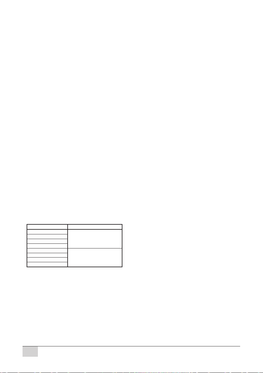
Tab. 1 Basic parameters of NDC displays
Type of display
Displaying
elements
Number of digits /
format
Digit height
(mm)
Readability range
(m)
NDC 57/4
superbright
7-segment LED
modules
4 / 88:885723
NDC 57/6
6 / 88:88:88
57
23
NDC 100/4
4 / 88:88
100
40
NDC 100/6
6 / 88:88:88
100
40
NDC 160/4
superbright elliptic
LEDs for outdoor
use
4 / 88:88
160
70
NDC 160/6
6 / 88:88:88
160
70
NDC 212/4
4 / 88:88
212
100
NDC 212/6
6 / 88:88:88
212
100
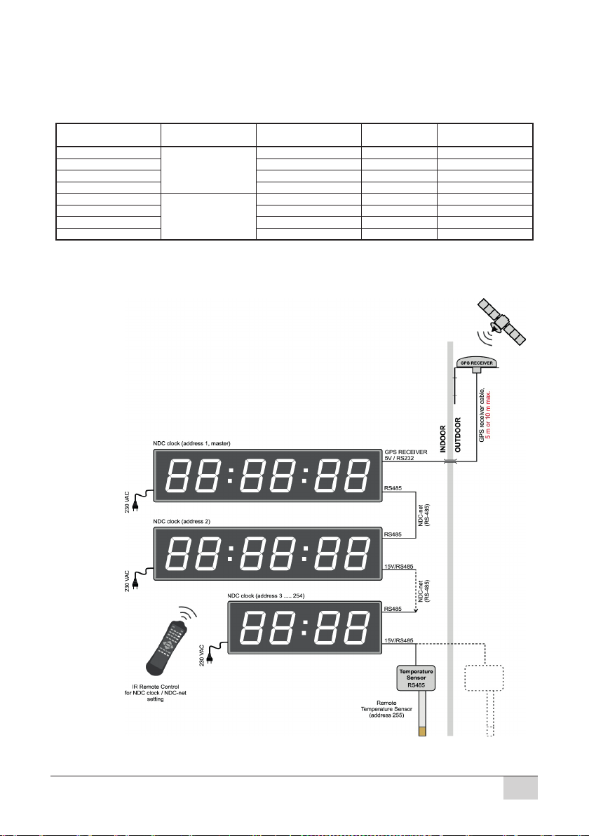
All displays have 2 connectors for a 2-wire or 3-wire RS485 communication interface and can be connected
into a communication network. If the displays are connected into a communication network (Fig. 1), any of
them can be controlled via a handheld infrared controler. Up to 127 devices can be connected to an NDC-net.
Fig. 1 Connection of NDC displays in a communication network
Digital clocks – NDC Series / User Manual v. 2.11
3

The easiest way of controlling the NDC clock is shown in fig. 2.
Fig. 2 The easiest way of controlling the NDC clock.
2 PROPERTIES
2.1 Display functions
• Time (display format)
− HH:MM (Hours:Minutes) NDC xxx/4;
− HH:MM:SS (Hours:Minutes:Seconds) NDC xxx/6.
• Date (display format)
− DD:MM (Day:Month) NDC xxx/4;
− DD:MM:YY (Day:Month:Year) NDC xxx/6.
• Temperature* (display format)
− -99° ÷ -10° ÷ -9.9° ÷ 99.9° NDC xxx/4;
− -99°C ÷ -10°C ÷ -9.9°C ÷ 99.9°C NDC xxx/6;
− A local thermal sensor (i.e. connected directy to the clock) can be located near the NDC or as part of
the frame (for extra fee). The precision of the displayed temperature is given by the precision of the
sensor.
* if a local thermal sensor is connected
• Stop watch
− SS.ss –> MM:SS NDC xxx/4
Seconds.hundredths of seconds with automatic switching to Minutes:Seconds when the seconds are
full;
− MM:SS.hh -> HH:MM:SS NDC .../6m
Minutes:Seconds.hundredths of seconds with selectable automatic switching to Hours:Minutes:Seconds
or a 99-minute mode (MM:SS.hh)
− Functions: START, STOP/FREEZE (intermediate time, the measured time runs in the background),
RESUME, RESET ;
− Automatic restart of the stop watch when the maximum displayable time is reached;
− Remote control of the stop watch, external contact (with or without galvanic separation) or with a remote
button in the NDC-net.
• Counter (counting up/down)
− Automatic switching of the display format, range: 1 s to 99 days, 23 hours, 59 minutes, 59 seconds;
− COUNT-UP or COUNT-DOWN mode – adjustable limit;
− Functions: START, STOP/PAUSE, RESUME, RESET;
− Single or repeated run of the counter when the setup limit is reached;
− Switchable counter time correction due to a time change (new time setting) or external time
synchronisation;
− Control of the counter via a remote control, an external contact (with or without galvanic separation) or
a remote button in the NDC-net;
− Possibility to switch on either the internal or a remote relay (close contact) when the limit is reached.
• Switch clock (time interval programming)
− Programmable 16 intervals of switching on the output relay in a single da y;
− Setting of the relay switch on period from 0.01 – 99 sec;
− Weekly calendar, setting of switch-on days (from Sunday to Saturday).
• Data from remote sensors (in NDC-net)
− Possibility to display data from 2 remote sensors connected to the NDC-net (e.g. external temperature
sensor, humidity sensor, pressure sensor, ...). It is possible to set on the clock the remote sensors whose
data will be displayed. If a local thermal sensor is connected, then it is possible to display just one figure
from a remote sensor.
• The clock allows alternate display of the above data, while the user has the possibility to program the
duration of their displaying in the range 0 ÷ 60s (0 – no data displayed).
• Automatic (depending on ambient light conditions) or manual brightness setting in 15 levels.
4
Digital clocks – NDC Series / User Manual v. 2.11

2.2 Display
The height of the display elements is 57, 100, 160 or 212 mm (readability up to 23, 40, 70 and 100 m
respectively). NDC 57/x and NDC 100/x types use superbright 7-segment LED modules. Other LED colours
are possible by agreement for an extra fee. NDC 160/x and NDC 212/x types use superbright elliptic LEDs to
ensure their legibility even in direct sunlight (outdoor).
2.3 Synchronisation, precision
• Possibility of external tim e synchronisation by means of synchronisation modules (e.g. GPS receiver).
• Time display precision:
– Autonomous time: ±30sec/month (in +20°C ÷ +30°C temperature range);
– When an external synchronisation module is connected, the precision is given by the precision of the
synchronisation.
2.4 Inputs, outputs
• RS485 interface with galvanic isolation for the interconnection with other devices in an NDC-net.
• An input for the connection of a local button with or without galvanic separation for controlling the stop
watch/counter. The maximum length of the local button’s cable is 3 – 5 m (according to the level of
interference).
• An input for the connection of a local thermal sensor (2 m as standard, or up to 5 m max. as per request)
• Built-in output relay 2 A/250 VAC, which can be closed for 0.1 s – 99 s in the counter mode when the setup
limit is reached or as the output of the switch clock.
• GPS Time Receiver input.
2.5 Settings
• Time setting manual, wireless via an IR controller or automatic, when an external synchronisation module
is connected.
• Manual or automatic LED brightness control based on the external illumination.
• Programming and setting of the clock via a wireless IR controller (max. perpendicular distance 15 m):
− Time and date setting;
− Activation of selected display modes (time, date, temperature, stop watch, counter, remote sensor) –
intervals of alternating data display;
− Limit and modes for the counter;
− Stop watch format;
− Stop watch and counter control;
− Enabling/disabling of daylight saving time (DST);
− Time shifting in the range ±23 hrs 59 min – correct displaying of times in different time zones with external
synchronisation;
− Manual time setting;
− Counter relay switch-on time setting;
− Selection of a local or remote sensor 1 in an NDC-net to be displayed;
− Selection of a local or remote sensor 2 in an NDC-net to be displayed;
− Selection of the remote input in an NDC-net (only the Master clock, see chapter 2.9 NDC-net
communication network below);
− Interval of synchronisation with other clocks in the NDC-net (only the Master clock);
− Switching clock – times and periods of switching-on the internal relay, weekly calendar.
2.6 Modifications and dimensions
• NDC 57/x, 100/x – frame of the clock is made of high-quality anodised aluminium profiles in a matt platinum
grey colour with a metallic appearance. Protection class: IP 20. Operation temperature range: -5°C ÷
+50°C.
• NDC 160/x, 212/x – outdoor clock, installed in an internal steel, powder paint coated frame; the external
cover frame is made of aluminium profiles in the colour of matt natural anodised aluminium. Protection
Class: IP 54. Operation temperature range: -30°C ÷ +50°C.
Display
Width
Height
Thickness
Readability range
Poznámky
NDC 57/4
360
1503823 m
wall-mounted
NDC 57/6
460
1503823 m
wall-mounted
NDC 100/4
530
2003840 m
wall-mounted
NDC 100/6
730
2003840 m
wall-mounted
NDC 160/4
685
340
110/217*
70 m
* with tilting wall bracket
NDC 160/6
990
340
110/217*
70 m
* with tilting wall bracket
NDC 212/4
890
400
110/217*
100 m
* with tilting wall bracket
NDC 212/6
1280
400
110/217*
100 m
* with tilting wall bracket
Digital clocks – NDC Series / User Manual v. 2.11
5
2.7 Power supply
Standard 230 VAC/50 Hz,12 VDC and 24 VDC for extra fee.
2.8 System time network
• Possibility to create unified time systems in an NDC-net without the necessity to use special master clock.
The unified time network may contain NDC clocks, GPS receiver, a synchronisation time module (Network
Time Server RS485), remote sensors (e.g. of temperature), remote buttons to control stop watch and the
counter and a remote output module (relay), controlled by the so called Master clock (i.e. standard NDC
clock setup as the Master, see below).
• Adjustable network clock synchronisation interval in the range 0 – 255 min (only the Master clock).
2.9 NDC-net communication network
At the physical level, the communication network is made by an RS485 interface with the baud rate 9600.
Devices with addresses 1 – 127 may be connected to the NDC-net bus, while there must be one NDC type
device with a dedicated address 1 in the function of the Master in the system. The bus negotiation and
communication control is always controlled by the Master device.
Devices connected to the bus may be of the following types:
• NDC clock – It displays data and, together with a remote controller, provides a user interface for the setting
and controlling of the system. The network must contain one NDC clock with the address set to 1 (Master
clock), which provides the control of the NDC-net.
• Synchronisation device – its role is to provide precise time to the rest of the devices. The source of that
time may be a GPS signal, DCF-77, a PC, an embedded module with an RS485 line and a protocol
converter to the NDC-net.
• Sensors – Within the range of the NDC-net they measure general quantities (usually temperature, but also
humidity, pressure,...) and, after their processing, they send the data along the network to NDC devices
for displaying. Data from one of two sensors may be allocated to each NDC clock. The sensor modules
will complement the offer depending on the demand on the market and the development possibilities.
• Remote buttons – They allow to place buttons for controlling the stop watch and the counter into a longer
distance from the controlled NDC within the NDC-net.
• Remote access – allows to place the switching relay or an open-collector type output to a longer distance
from the controlling NDC within the NDC-net. This output may be controlled only by the Master clock.
3 DISPLAY ACCESSORIES
Depending on the selected version of the connection of displays, the supply is complemented with the
necessary accessories.
3.1 Standard accessories
Typ e of display
Standard accessories
NDC 57/4
Power supply cable
flexible 1.5 m.
NDC 57/6
NDC 100/4
NDC 100/6
NDC 160/4
Connector for the
power supply cable.
(Cable is not supplied.)
NDC 160/6
NDC 212/4
NDC 212/6
3.2 Optional accessories
• Handheld IR Remote Control – for setting clock parameters.
(Parameters such as time, date, on/off time period of each displayed value, brightness, etc.).
• Temperature sensor – for displaying local or remote temperature (as per type ordered).
• GPS Time Receiver – for automatic time/date synchronization with GPS
(GPS Timer Receiver cable length can be 5 m or 10 m max., depending on type ordered).
Several modules can be connected to NDC series clocks and to the NDC-net through a communication bus
based on RS485, which communicate with the NDC-protocol. The range of such modules is widened
continually.
6
Digital clocks – NDC Series / User Manual v. 2.11
 Loading...