

Page 1

Kelvin™ BRICK
User’s Guide
Page 2

Kelvin™ BRICK User’s Guide
Rev. 1.00, August, 2007
Part #117-0153
Copyright © Element Labs, Inc.
The Element Labs logo and Kelvin™ are trademarks of Element Labs, Inc.
Other trademarks and trade names may be used in this document to refer to products by other
entities. Element Labs, Inc. claims no proprietary interest in trademarks and trade names owned
by others.
Information and specifications in this document are subject to change without notice. Element
Labs, Inc. assumes no responsibility or liability for any errors or inaccuracies that may appear in
this manual.
Contact Info
Element Labs, Inc.
9701 Metric Boulevard
Suite 200
Austin, TX 78758
United States
tel +1 512 491 9111
fax +1 512 491 9122
Element Labs GmbH
Lindener Str. 15
D-38300 Wolfenbüttel
Germany
tel +49 5331 905660
fax +49 5331 905661
Element Labs Ltd.
19A Perseverance Works
38 Kingsland Road
London E2 8DD
United Kingdom
tel +44 (0) 20 7749 0611
fax +44 (0) 20 7749 0622
http://www.elementlabs.com
[email protected]
Kelvin™ BRICK User’s Guide
Page 3

T
ABLE OF CONTENTS
Chapter 1: Introduction 1-1
General Info ______________________________________________ 1-1
Kelvin™ BRICK Features ___________________________________ 1-1
Kelvin BRICK Parts _________________________________________ 1-2
Chapter 2: Setup 2-1
Mounting ________________________________________________ 2-1
Power Connection _________________________________________ 2-3
Silicone Boot _____________________________________________ 2-3
Chapter 3: IR Remote Control 3-1
General Info ______________________________________________ 3-1
Installing the Batteries ___________________________________ 3-2
IR Remote Control Operation ______________________________ 3-2
IR Remote Control Button Descriptions ________________________ 3-4
Chapter 4: DMX Control 4-1
General Info ______________________________________________ 4-1
DMX Connections _________________________________________ 4-1
DMX Setup Diagram _______________________________________ 4-2
Appendix A: DMX Protocol A-1
Introduction ______________________________________________ A-1
Auto Fade Mode _______________________________________ A-2
Film & Video Mode _________________________________________ A-3
RGB Mode ________________________________________________ A-7
6 Color Mode ____________________________________________ A-10
Kelvin™ BRICK User’s Guide TOC-1
Page 4
C HAPTER
1
General Info
Kelvin™ BRICK Features
Chapter 1 I
• 6 LED colors (red, green, blue, cyan, orange, white)
•Variable Intensity
• Variable CCT (Correlated Color Temperature)
• DMX Compatible
• Handheld IR Remote Control
NTRODUCTION
Kelvin™ BRICK User’s Guide 1-1
Page 5

Kelvin BRICK Parts
The following is a list of accessory and replacement parts available for the BRICK.
part # description
515-0100 Kelvin BRICK
370-0160 Silicone Boot
370-0161 Clear Outer Lens
370-0183 Clear Inner Lens
370-0184 Diffused Outer Lens
515-0101 IR Remote Control
360-0151 Standard Yoke
360-0152 Compact Yoke
352-0201 Power Cable; IEC Female to Edison; 6 ft. (1.83m)
350-0139 Data Cable In; 10 pin Brick Data Connector (BDC) to 5 pin XLR male
(DMX); 6 ft. (1.83m)
350-0140 Data Cable Out; 12 pin BDC to 5 pin XLR female (DMX); 6 ft. (1.83m)
350-0141 Data Cable Interconnect; 10 pin BDC to 12 pin BDC for connecting
Brick to Brick; 2’ (.6 meter)
Chapter 1
Introduction
Table 1.1
BRICK Accessory & Replacement Parts
Kelvin™ BRICK User’s Guide 1-2
Page 6

C HAPTER
(p/n 360-0151)
Standard Yoke
Compact Yoke
(p/n 360-0152)
2
Mounting
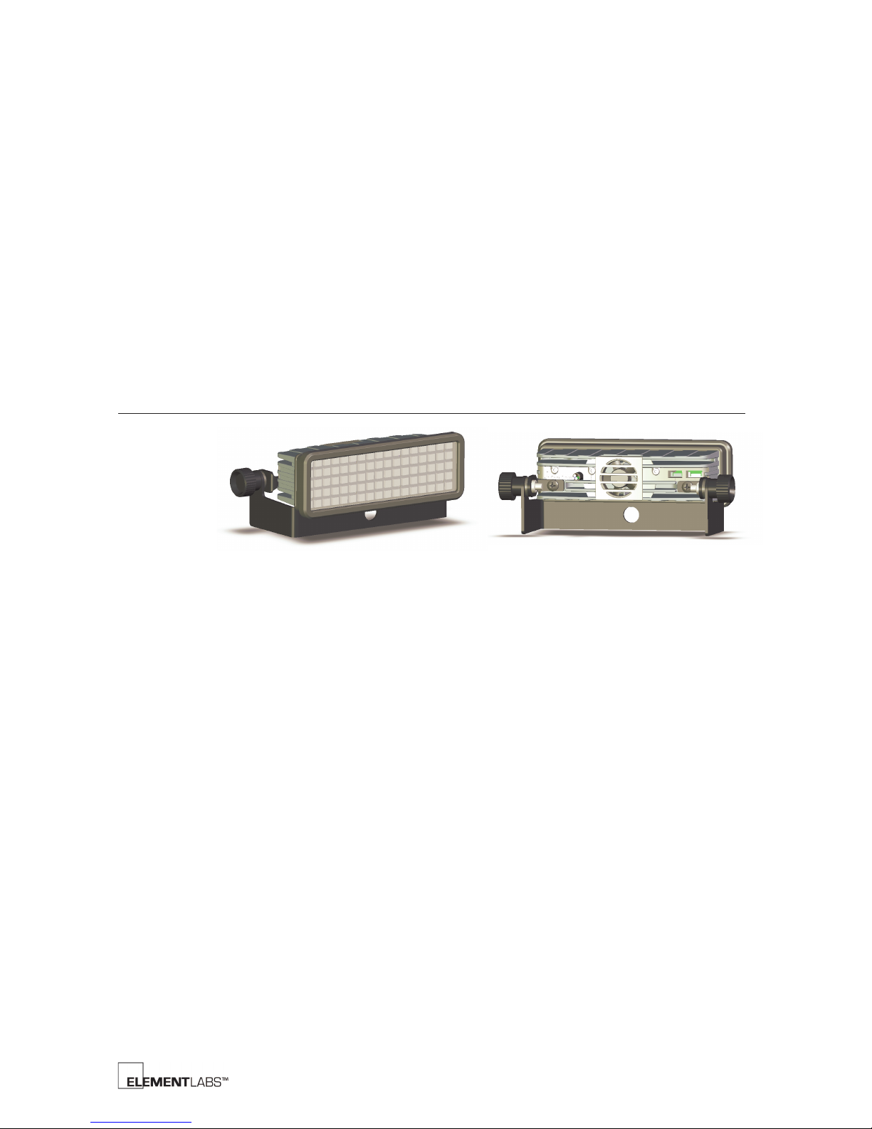
The Kelvin™ BRICK can be mounted using either of the 2 included yokes. The standard
yoke comes attached and tucks under the BRICK allowing it to sit on a flat surface. The
compact yoke allows mounting the BRICK in a tighter space.
Chapter 2 S
ETUP
Figure 2.1
BRICK Yoke Styles
Kelvin™ BRICK User’s Guide 2-1
Page 7
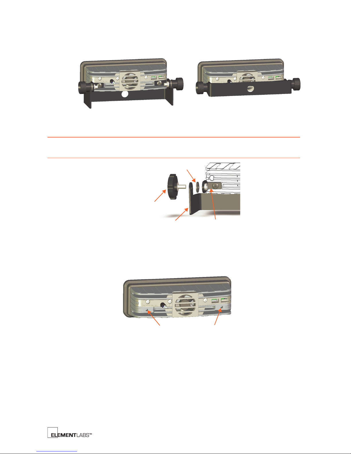
Each yoke has a 13mm (1/2”) hole for mounting to a variety of equipment.
Yoke
Rubber Washer
Mounting Bracket
Tightening
Knob
Mounting Holes (M5 depth 6.5mm)
Chapter 2
Setup
NOTE
Figure 2.2
BRICK Yoke Mounting Holes
When attaching the yoke to the mounting bracket, place the rubber washer
between the yoke and the mounting bracket, as shown below.
Figure 2.3
BRICK Yoke Assembly
The yoke mounting brackets can be removed from the BRICK allowing the M5 holes to
be used for custom mounting options.
Figure 2.4
BRICK rear view
Kelvin™ BRICK User’s Guide 2-2
Page 8
Power Connection
Hot
Ground
Neutral
(Blue)
(Brown)
(Green/Yellow)
Outer Lens Slot Inner Lens Slot
157.98mm x 49.19mm
(6.22” x 1.94”)
154mm x 45.2mm
(6.06” x 1.78”)
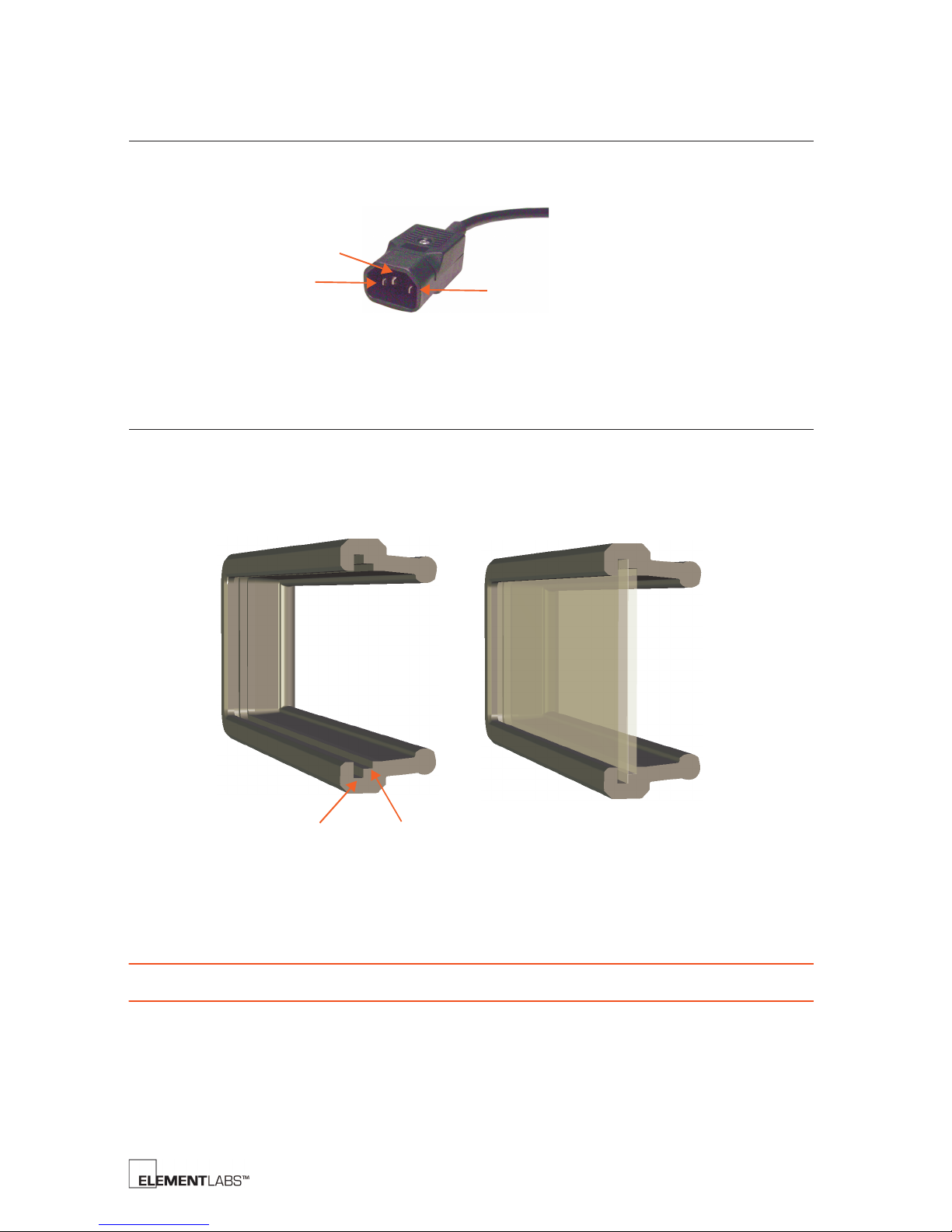
The BRICK ships with a standard male IEC AC power connector handling 100-240VAC,
50/60Hz.
Chapter 2
Setup
Figure 2.5
Silicone Boot
The Kelvin BRICK ships with a silicone boot around the front to provide protection. The
boot can also hold 2 plastic lenses (clear and diffused). The boot has 2 slots so 2 lenses
can be used at the same time. If desired, gel, diffusion, or brightness enhancing film can
be cut to fit between these 2 lenses.
BRICK AC Connector
Figure 2.6
NOTE
If only one lens is used, it must be installed in the outer lens slot.
BRICK Boot Cross Section
Kelvin™ BRICK User’s Guide 2-3
Page 9

Chapter 2
Setup
The boot can be removed by pulling it away from the BRICK. The plastic lenses can then
be installed or removed.
Figure 2.7
BRICK Boot & Plastic Lenses
Kelvin™ BRICK User’s Guide 2-4
Page 10
C HAPTER
Light On/Off
Adjustment
Controls
Mode
Data Entry
Function
CCT Preset
LED Color
or
3
General Info
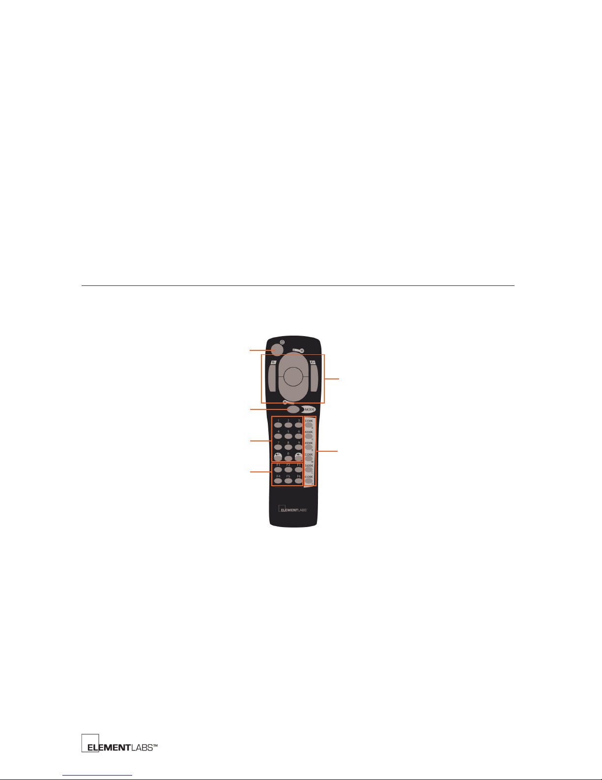
The handheld infrared (IR) remote allows you to control many features of the Kelvin™
BRICK. Each of the button groups outlined below are detailed later in this chapter.
Chapter 3 IR R
EMOTE
C
ONTROL
Figure 3.1
IR Remote Control
Kelvin™ BRICK User’s Guide 3-1
Page 11
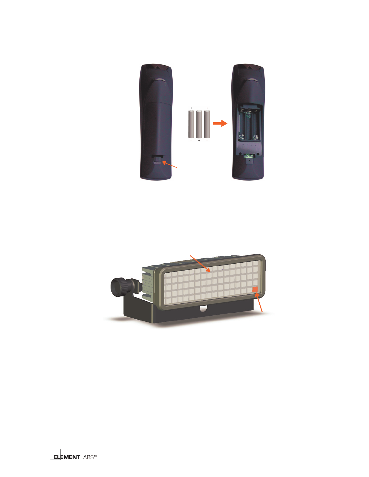
Installing the Batteries
Battery Cover
Release Tab
Signal Indicator
IR Sensor
The IR handheld remote control requires 3xAAA batteries to operate.
Chapter 3
IR Remote Control
Figure 3.2
Battery Installation
IR Remote Control Operation
Each BRICK has an IR sensor on the front of the LED array. In addition, the lower right
LED on each BRICK indicates IR signal reception.
Figure 3.3
The indicator LED flashes red once when a command has been received from the IR
remote. Additionally, the indicator LED flashes red 3 times when you have reached the
upper or lower limit of a parameter via the remote.
IR Sensor and Signal Indicator
Kelvin™ BRICK User’s Guide 3-2
Page 12
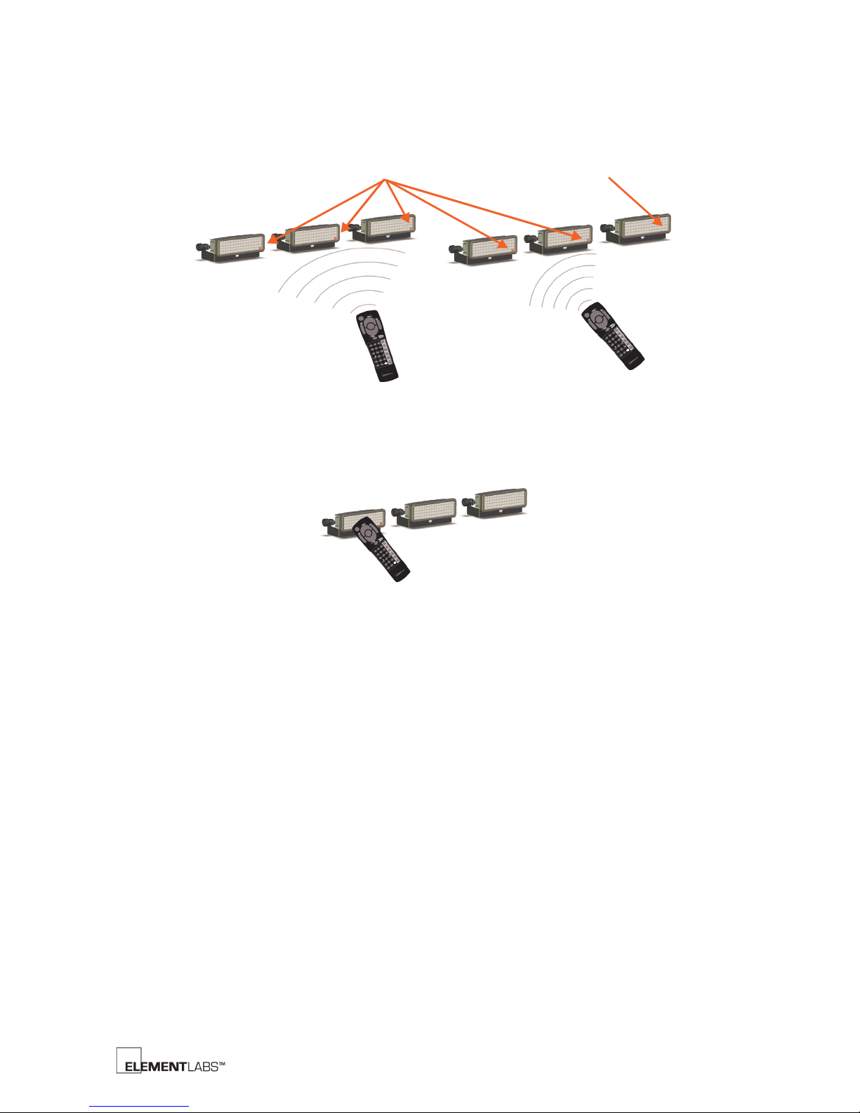
Chapter 3
Received Signal OK
Did Not Receive Signal
IR Remote Control
A single remote can control multiple BRICKs if used far enough away for the signal to
cover all the BRICKs.
Figure 3.4
Multiple Brick IR Control
Additionally, a single BRICK can be controlled by placing the remote control directly in
front of the IR sensor.
Figure 3.5
Single Brick IR Control
Kelvin™ BRICK User’s Guide 3-3
Page 13
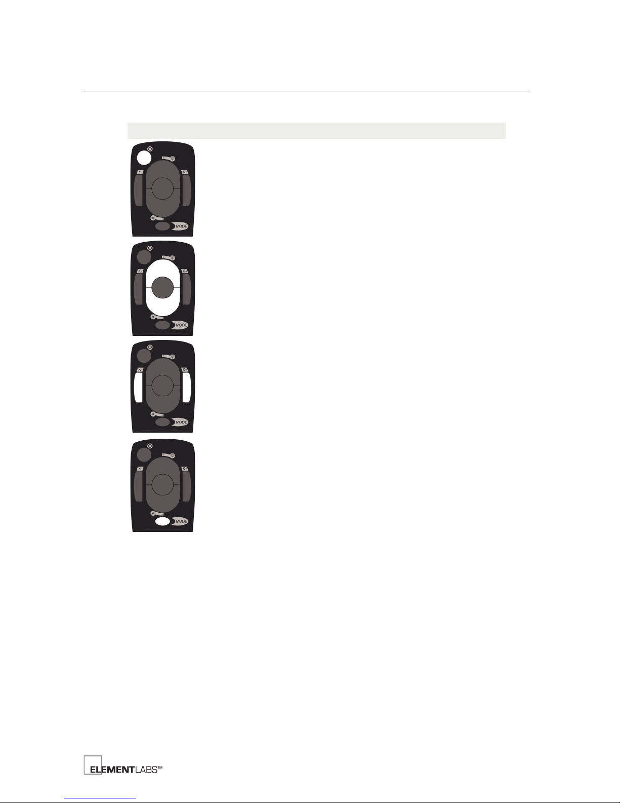
IR Remote Control Button Descriptions
Button Description
Light Output On /Off
• Turns the light output of the fixture on or off. This is the
equivalent of a blackout or DBO button.
NOTE Settings are saved when you turn the light output off.
Intensity
• Top button increases intensity.
• Bottom button decreases intensity.
• Press and hold increases or decreases intensity.
Chapter 3
IR Remote Control
Correlated Color Temperature (CCT)
• Left button increases CCT (cooler).
• Right button decreases CCT (warmer).
• Press and hold increases or decreases CCT.
Mode
• Turns on or off the Demo mode. The Demo mode showcases the
functionality for demonstration purposes only.
Kelvin™ BRICK User’s Guide 3-4
Page 14
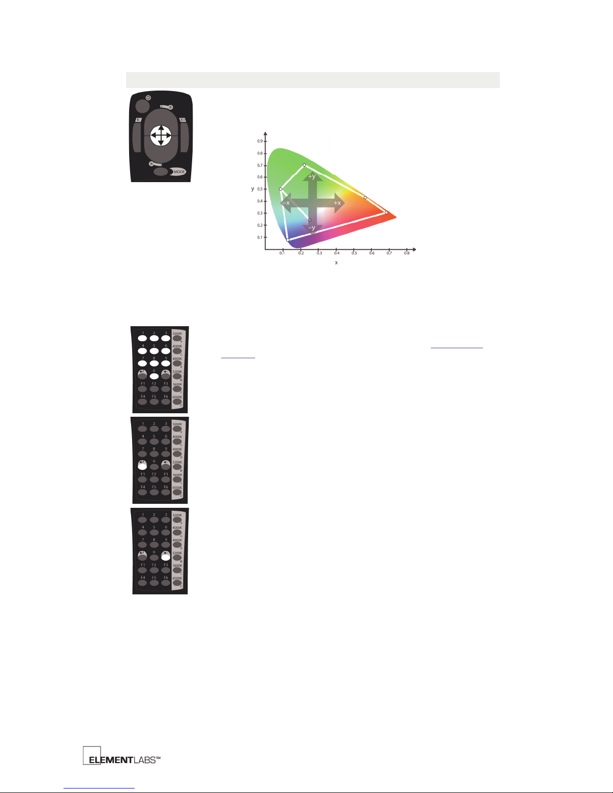
Button Description
Chromaticity (x,y) Adjustment
The middle, 4-way button allows control of the x and y chromaticity
values.
• Left decreases the x chromaticity value.
• Right increases the x chromaticity value.
• Down decreases the y chromaticity value.
• Up increases the y chromaticity value.
Numeric keys (0 to 9)
• Use these keys when entering a DMX address (see F1: Set DMX
Address (p. 3-7).
Chapter 3
IR Remote Control
Enter
• Sends the numeric entry.
Clear
• Clears the numeric entry.
Kelvin™ BRICK User’s Guide 3-5
Page 15
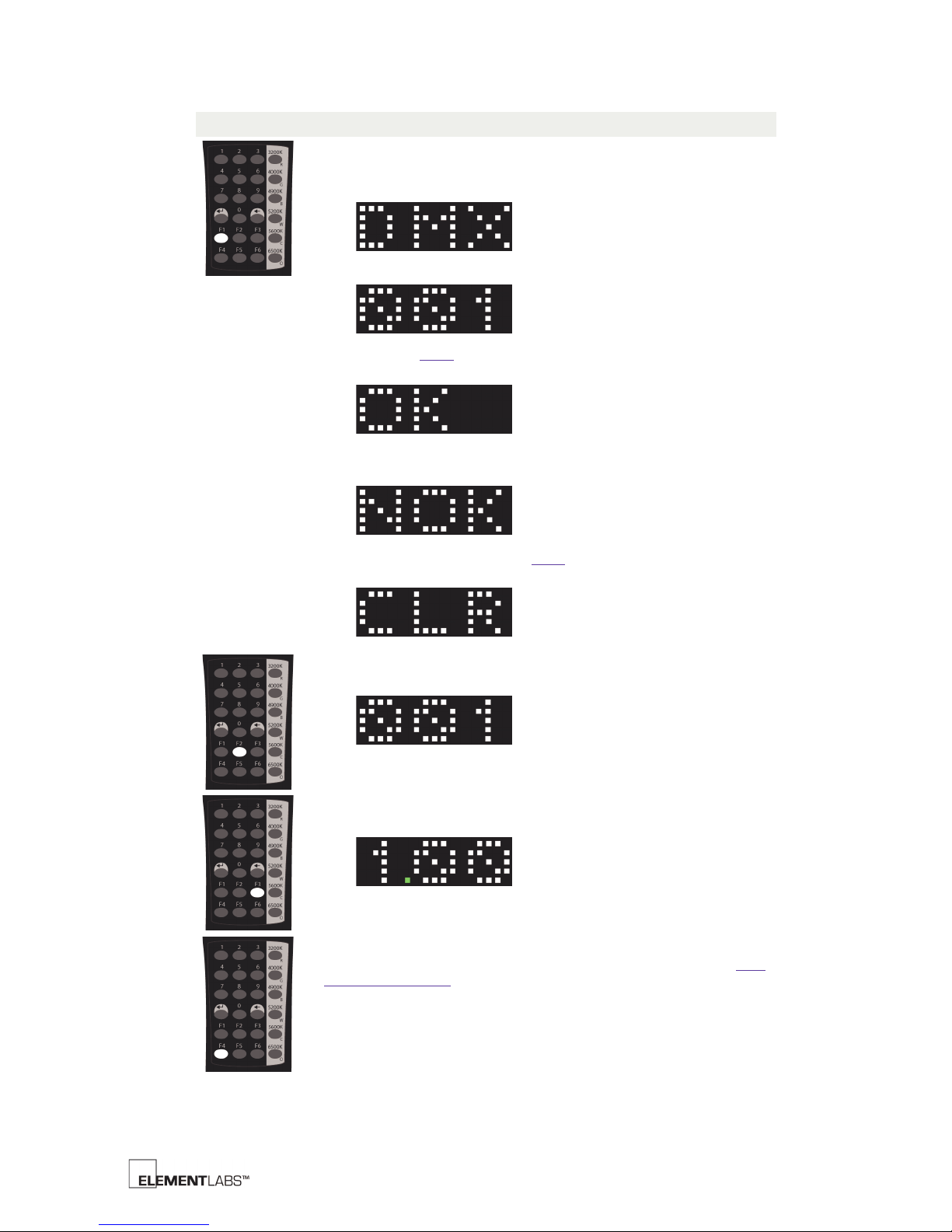
Button Description
F1: Set DMX Address
Follow the steps below to set the DMX address:
1. Press the F1 button.
2. Enter the desired DMX address.
Chapter 3
IR Remote Control
3. Press the Enter
button.
If the address was accepted, the fixture will respond with OK.
If the address entered is not within the valid range of 1-501, the
BRICK will respond with NOK.
If you make a mistake, press the Clear
button and start again with
step #1 above.
F2: Display DMX Address
Display the current DMX address.
F3: Display Firmware
Displays the current firmware version.
F4: CCT or Color Mode
Toggles the operating mode of the CCT Preset buttons. Refer to CCT
Presets/Color Mode below for more information.
Kelvin™ BRICK User’s Guide 3-6
Page 16
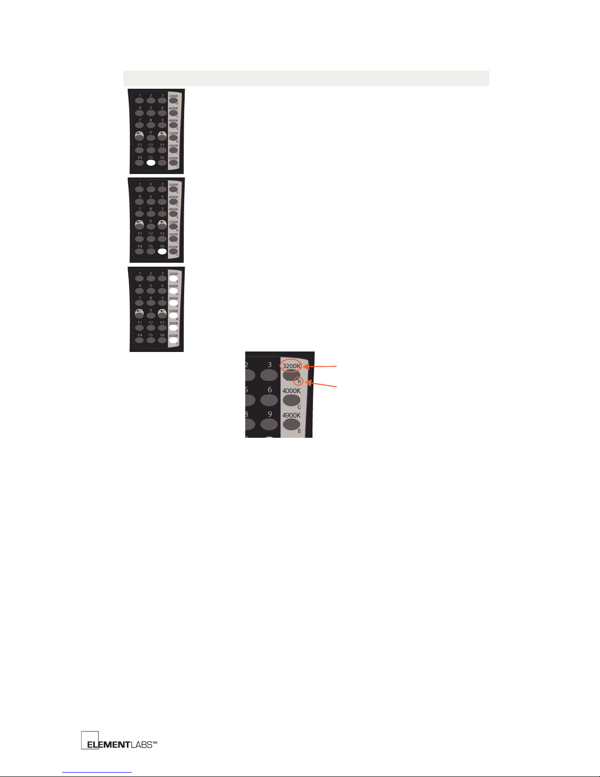
Button Description
3200K CCT Label
Red LED Label
F5
(not implemented yet)
F6
(not implemented yet)
CCT Presets/Color Mode
• In CCT mode, these buttons select one of the 6 preset Correlated
Color Temperature values.
• In color mode, these buttons toggle on/off all LEDs of a specific
color.
Each of these buttons have 2 labels to indicate the CCT Preset or the
LED Color.
Chapter 3
IR Remote Control
Kelvin™ BRICK User’s Guide 3-7
Page 17
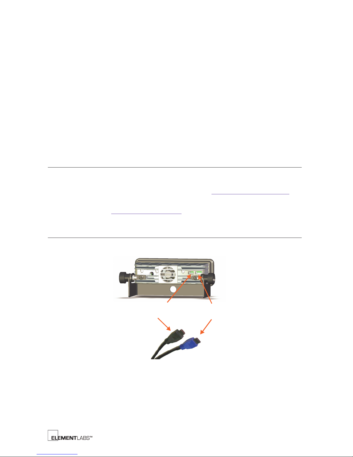
C HAPTER
DMX Out/Through
DMX In
(10 pin black connector) (12 pin blue connector)
4
General Info
The Kelvin BRICK supports the DMX 512 Protocol (ANSI E1.11 / USITT DMX512-A).
Element Labs has worked with several DMX console manufacturers to create a Kelvin
fixture profile. Please visit the Element Labs website (http://www.elementlabs.com) for
the latest version of the Kelvin DMX protocol and fixture profiles.
Please refer to Appendix A: DMX Protocol
DMX Connections
The Kelvin BRICK has 2 connectors on the rear of the unit that are used for DMX control.
Chapter 4 DMX C
, (p. A-1) for detailed DMX information.
ONTROL
Figure 4.1
BRICK DMX Connectors
Kelvin™ BRICK User’s Guide 4-1
Page 18
Chapter 4
DMX Control
Cables are available from Element Labs that adapt the BRICK Data Connector (BDC) to a
standard 5-pin XLR connector and for BRICK to BRICK interconnection.
Part # Description Length
350-0139 BRICK Data In: BDC to 5 pin XLR Female 6’ (1.8 meter)
350-0140 BRICK Data Out: BDC to 5 pin XLR Male 6’ (1.8 meter)
350-0141 BRICK Data Interconnect: BDC to BDC 2’ (.6 meter)
Table 4.2
BRICK Data Cables
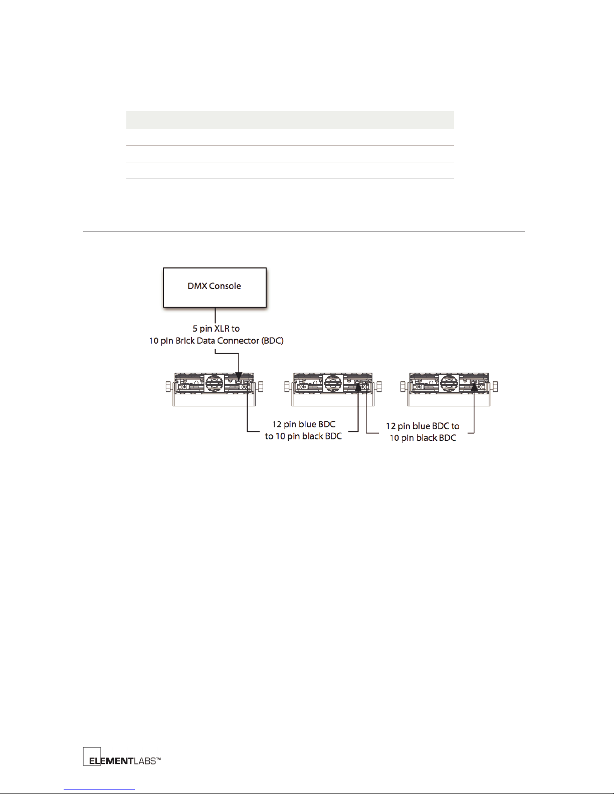
DMX Setup Diagram
The following diagram illustrates a simple DMX setup with multiple BRICKs.
Figure 4.3
Data Connection Diagram
Kelvin™ BRICK User’s Guide 4-2
Page 19
Introduction
This appendix details Element Labs DMX Protocol, revision 1.11. The protocol defines 3
modes of operation. Most modes use 10 DMX channels as shown in the table below.
DMX Ch. Film / Video Mode RGB Mode 6 Color Mode
1 Mode Mode Mode
2 Intensity Intensity Intensity
3 Correlated Color
4 C.T.B. Filter Red Green
5 C.T.O. Filter Green Blue
6ND Filter Blue Cyan
7 Plus / Minus Green Filter Orange
8AutoFade Time AutoFade Time White
9 Strobe Duration Strobe Duration Strobe Duration
10 Strobe Rate Strobe Rate Strobe Rate
Temperature (CCT)
Correlated Color
Temperature (CCT)
A PPENDIX
Appendix A
DMX P
Red
A
ROTOCOL
Table D.3
DMX Modes and Functions
Kelvin™ BRICK User’s Guide A-1
Page 20

Appendix A
DMX Protocol
Introduction
Channel 1 defines the mode for each fixture, as shown in the table below. The default
mode is Film & Video (0%/000).
DMX Percent DMX Decimal Mode Mode Description
0 - 5% 000-012 1 Film & Video
6 - 15% 015-038 2 RGB Mode
16 - 25% 040-063 3 6 Color Mode
Table D.4
DMX Channel 1 Details
Auto Fade Mode
The DMX Auto Fade mode allows you to smoothly transition (fade) between settings.
For example, set the intensity to 80% and Auto Fade Time to 1 second. Now adjust the
intensity to 20%. The fixture will take 1 second to transition between 80% intensity and
20% intensity.
Kelvin™ BRICK User’s Guide A-2
Page 21

Film & Video Mode
DMX Channel Function
1Mode
2Intensity
3 Correlated Color Temperature (CCT)
4
5
6
7
8AutoFade Time
9 Strobe Duration
10 Strobe Rate
Channel 2 - Intensity
default=off (0% / 000)
percent decimal
0% 000 off
↓↓↓
100% 255 Full intensity
C.T.B. Filter
C.T.O. Filter
ND Filter
Plus / Minus
Green Filter
Appendix A
DMX Protocol
Film & Video Mode
NOTE
These 4 channels
are relative to
the CCT selected
via channel 3.
Channel 3 - Correlated Color Temperature
default=3200K (10% / 025)
percent decimal CCT preset
0 - 5% 000-012 2900K Warm Tungsten
6 - 15% 015-038 3200K Tungsten
16 - 25% 040-063 3400K Fluorescent Warm White
26 - 35% 066-089 3600K Fluorescent Warm White
36 - 45% 091-114 4300K 50/50 Tungsten Daylight
Mix
46 - 55% 117-140 4800K Fluorescent White
56 - 65% 142-165 5000K D50
66 - 75% 168-191 5500K Daylight 1
76 - 85% 193-216 5600K Daylight 2
86 - 95% 219-242 5700K Fluorescent Cool White /
Fluorescent Daylight
96 - 100% 244-255 6500K D65
Kelvin™ BRICK User’s Guide A-3
Page 22

Channel 4 - C.T.B. Filter
default=none (0% / 000)
percent decimal C.T.B. preset Lee Rosco
0 - 5% 000-012 none
6 - 15% 015-038 1/8 C.T.B. 218 3216 1535
16 - 25% 040-063 1/4 C.T.B. 203 3208 1532
26 - 35% 066-089 1/2 C.T.B. 202 3204 1529
36 - 45% 091-114 3/4 C.T.B. 281 3203 1526
46 - 55% 117-140 1 C.T.B. 201 3202 1523
56 - 65% 142-165 1 1/4 C.T.B.
66 - 75% 168-191 1 1/2 C.T.B.
76 - 85% 193-216 1 3/4 C.T.B.
86 - 95% 219-242 2 C.T.B. 200 3220
96 - 100% 244-255 2 1/4 C.T.B.
Gel Equivalent
Cinegel
GAM
Cinefilter
Channel 5 - C.T.O. Filter
default=none (0% / 000)
percent decimal C.T.O. preset Lee Rosco
0 - 5% 000-012 none
6 - 15% 015-038 1/8 C.T.O. 223 3410 1555
16 - 25% 040-063 1/4 C.T.O. 206 3409 1552
26 - 35% 066-089 1/2 C.T.O. 205 3408 1549
36 - 45% 091-114 3/4 C.T.O. 285 3411 1546
46 - 55% 117-140 1 C.T.O. 204 3407 1543
56 - 65% 142-165 1 1/4 C.T.O.
66 - 75% 168-191 1 1/2 C.T.O.
76 - 85% 193-216 1 3/4 C.T.O.
86 - 95% 219-242 2 C.T.O. 3420
96 - 100% 244-255 2 1/4 C.T.O.
Gel Equivalent
Cinegel
GAM
Cinefilter
Appendix A
DMX Protocol
Film & Video Mode
Kelvin™ BRICK User’s Guide A-4
Page 23

Appendix A
DMX Protocol
Film & Video Mode
Channel 6 - Neutral Density Filter
default=none (0% / 000)
percent decimal ND preset Lee Rosco
0 - 5% 000-012 none
6 - 15% 015-038 .07ND (-1/4 Stop)
16 - 25% 040-063 .15ND (-1/2 Stop) 298 3415 1514
26 - 35% 066-089 .30ND (-1 Stop) 209 3402 1515
36 - 45% 091-114 .45ND (-1.5 Stops)
46 - 55% 117-140 .60ND (-2 Stops) 210 3403 1516
56 - 65% 142-165 .75ND (-2.5 Stops)
66 - 75% 168-191 .9ND (-3 Stops) 211 3404 1517
76 - 85% 193-216 1.05ND (-3.5 Stops)
86 - 95% 219-242 1.2 ND (-4 Stops) 299 1518
96 - 100% 244-255 1.5ND (-5 Stops)
Gel Equivalent
Cinegel
GAM
Cinefilter
Channel 7 - Plus/Minus Green Filter Details
default=none (0% / 000)
percent decimal Plus Green preset Lee Rosco
0 - 5% 000-012 none
6 - 15% 015-038 Minus Green 247 3308 1580 CC30
16 - 25% 040-063 3/4 Minus Green 1581
26 - 35% 066-089 1/2 Minus Green 248 3313 1582 CC15
36 - 45% 091-114 1/4 Minus Green 249 3314 1583 CC075
46 - 55% 117-140 1/8 Minus Green 279 3318 1584
56 - 65% 142-165 1/8 Plus Green 278 3317 1589
66 - 75% 168-191 1/4 Plus Green 246 3316 1588 CC075
76 - 85% 193-216 1/2 Plus Green 245 3315 1587 CC15
86 - 95% 219-242 3/4 Plus Green
96 - 100% 244-255 Plus Green 244 3304 1585 CC30
Gel Equivalent
Cinegel
GAM
Cinefilter
Equiv.
Camera
Filter
Magenta
Magenta
Magenta
Green
Green
Green
Channel 8 - Autofade Time
default=off (0% / 000)
percent decimal time
0% 000 off
0.4% 001 0.1 sec.
↓↓↓
100% 255 25.5 sec.
NOTE
Fade time = decimal
DMX value * 0.1 seconds
Kelvin™ BRICK User’s Guide A-5
Page 24

Channel 9 - Strobe Duration
default=off (0% / 000)
percent decimal duration
0% 000 off
1% 002 1%
↓↓↓
100% 255 100%
NOTE
Duration = 100% will
appear the same as
Strobe “off” (i.e. fixture
may have intensity but
will not be flashing
because duration is
100%).
Channel 10 - Strobe Rate
default=0.25Hz (0% / 000)
Strobe Rate step = 0.25Hz
percent decimal rate (Hz1) rate (seconds per cycle)
0% 000 Frequency = 0.25Hz
↓↓↓
100% 255 Frequency = 64Hz
(sample settings)
.4 001 .5 2
.8 002 .75 1.33
1.2 003 1 1
2 005 1.5 .67
2.7 007 2.0 .5
4.3 011 3.0 .33
1. Hz=cycles per second
Appendix A
DMX Protocol
Film & Video Mode
Kelvin™ BRICK User’s Guide A-6
Page 25

RGB Mode
DMX Channel Function
Channel 2 - Intensity
default=off (0% / 000)
percent decimal
0% 000 off
↓↓↓
100% 255 Full intensity
1Mode
2Intensity
3 Correlated Color Temperature
4
5
6
7
8AutoFade Time
9 Strobe Duration
10 Strobe Rate
Red
Green
Blue
NOTE
These three channels are relative to
the CCT selected via channel 3.
Appendix A
DMX Protocol
RGB Mode
Channel 3 - Correlated Color Temperature
default=3200K (10% / 025)
percent decimal CCT preset
0 - 5% 000-012 2900K Warm Tungsten
6 - 15% 015-038 3200K Tungsten
16 - 25% 040-063 3400K Fluorescent Warm White
26 - 35% 066-089 3600K Fluorescent Warm White
36 - 45% 091-114 4300K 50/50 Tungsten Daylight Mix
46 - 55% 117-140 4800K Fluorescent White
56 - 65% 142-165 5000K D50
66 - 75% 168-191 5500K Daylight 1
76 - 85% 193-216 5600K Daylight 2
86 - 95% 219-242 5700K Fluorescent Cool White / Fluorescent
96 - 100% 244-255 6500K D65
Daylight
Channel 4 - Red
default=off (0% / 000)
percent decimal
0% 000 off
↓↓↓
100% 255 full red
Kelvin™ BRICK User’s Guide A-7
Page 26

Channel 5 - Green
default=off (0% / 000)
percent decimal
0% 000 off
↓↓↓
100% 255 full green
Channel 6 - Blue
default=off (0% / 000)
percent decimal
0% 000 off
↓↓↓
100% 255 full blue
Channel 8 - Autofade Time
default=off (0% / 000)
percent decimal time
0% 000 AutoFade off
0.4% 001 AutoFade = 0.1 sec.
↓↓↓
100% 255 AutoFade = 25.5 sec.
Appendix A
DMX Protocol
RGB Mode
NOTE
Fade time = decimal DMX
value * 0.1 seconds
Channel 9 - Strobe Duration
default=off (0% / 000)
percent decimal duration
0% 000 off
1% 002 1%
↓↓↓
100% 255 100%
NOTE
Duration = 100% will appear the
same as Strobe “off”.
i.e. - fixture may have intensity but
will not be flashing because duration
is 100%
Kelvin™ BRICK User’s Guide A-8
Page 27

Channel 10 - Strobe Rate
default=0.25Hz (0% / 000)
Strobe Rate step = 0.25Hz
percent decimal rate (Hz1) rate (seconds per cycle)
0% 000 Frequency =
0.25Hz
↓↓↓
100% 255 Frequency = 64Hz
(sample settings)
.4 001 .5 2
.8 002 .75 1.33
1.2 003 1 1
2 005 1.5 .67
2.7 007 2.0 .5
4.3 011 3.0 .33
1. Hz=cycles per second
Appendix A
DMX Protocol
RGB Mode
Kelvin™ BRICK User’s Guide A-9
Page 28

6 Color Mode
DMX Channel Function
1Mode
2Intensity
3Red
4 Green
5Blue
6Cyan
7Orange
8White
9 Strobe Duration
10 Strobe Rate
Channel 2 - Intensity
default=off (0% / 000)
percent decimal
0% 000 off
↓↓↓
100% 255 Full intensity
Appendix A
DMX Protocol
6 Color Mode
Channel 3 - Red
default=off (0% / 000)
percent decimal
0% 000 off
↓↓↓
100% 255 full red
Channel 4 - Green
default=off (0% / 000)
percent decimal
0% 000 off
↓↓↓
100% 255 full green
Kelvin™ BRICK User’s Guide A-10
Page 29

Channel 5 - Blue
default=off (0% / 000)
percent decimal
0% 000 off
↓↓↓
100% 255 full blue
Channel 6 - Cyan
default=off (0% / 000)
percent decimal
0% 000 off
↓↓↓
100% 255 full cyan
Channel 7 - Orange
default=off (0% / 000)
percent decimal
0% 000 off
↓↓↓
100% 255 full orange
Appendix A
DMX Protocol
6 Color Mode
Channel 8 - White
default=off (0% / 000)
percent decimal
0% 0 off
↓↓↓
100% 255 full white
Channel 9 - Strobe Duration
default=off (0% / 000)
percent decimal duration
0% 000 off
1% 002 1%
↓↓↓
100% 255 100%
NOTE
Duration = 100% will appear the
same as Strobe “off”.
i.e. - fixture may have intensity but
will not be flashing because
duration is 100%
Kelvin™ BRICK User’s Guide A-11
Page 30

Channel 10 - Strobe Rate
default=0.25Hz (0% / 000)
Strobe Rate step = 0.25Hz
percent decimal rate (Hz1) rate (seconds per cycle)
0% 000 Frequency = 0.25Hz
↓↓↓
100% 255 Frequency = 64Hz
(sample settings)
.4 001 .5 2
.8 002 .75 1.33
1.2 003 1 1
2 005 1.5 .67
2.7 007 2.0 .5
4.3 011 3.0 .33
1. Hz=cycles per second
Appendix A
DMX Protocol
6 Color Mode
Kelvin™ BRICK User’s Guide A-12
Page 31

Page 32

www.elementlabs.com
 Loading...