

Variants Operating Instructions
vario EL cube
Analyzer
Version 17.02.2017
Elementar Analysensysteme GmbH
Variants Operating Instructions vario EL cube ©Elementar Analysensysteme GmbH

Copyright ©Elementar Analysensysteme GmbH
All rights reserved
This document contains proprietary information of Elementar Analysensysteme GmbH. Reprint is
prohibited.
Due to continued product development this information may change without notice. The information
and intellectual property contained herein is confidential between Elementar Analysensysteme GmbH
and the client and remains the exclusive property of Elementar Analysensysteme GmbH. If you find
any problems in the documentation, please report them to us. Elementar Analysensysteme GmbH
does not warrant that this document is error-free.
No part of this publication may be reproduced, stored in a data storage system, or transmitted in any
form or by any means, electronic, mechanical, photocopying, recording or otherwise without the prior
written permission of Elementar Analysensysteme GmbH.
Windows®, Windows XP®, Windows 7® and Windows 10®are trademarks of Microsoft Corporation.
MS-Excel® und MS-Access® are trademarks of Microsoft Corporation.
Elementar Analysensysteme GmbH
Elementar-Straße 1
63505 Langenselbold
Germany
+49 (0) 6184 9393 0
E-Mail: info@elementar.de
Internet: http://www.elementar.de
Variants Operating Instructions vario EL cube ©Elementar Analysensysteme GmbH

Contents 3
Contents
CHAPTER 1 General 7
Revision history ............................................................................................................................................. 8
About this document ...................................................................................................................................... 9
Display conventions .................................................................................................................................... 10
Working with the operating instructions ....................................................................................................... 10
General information on the operating instructions ....................................................................................... 10
Notes regarding modification ....................................................................................................................... 11
Warning notes during operation .................................................................................................................. 11
CHAPTER 2 Oxygen determination with TCD 13
Analytical characteristics and technical specifications ................................................................................. 14
Substance digestion and functional diagram ............................................................................................... 14
Separation of the reaction gases ................................................................................................................. 17
Detection ..................................................................................................................................................... 17
Tube fillings ................................................................................................................................................. 18
Modification to O Mode ............................................................................................................................... 19
Conditioning the pyrolysis tube ................................................................................................................... 23
Changing of the pyrolysis crucible ............................................................................................................... 24
Establishing of the analysis readiness ......................................................................................................... 25
Notes on performing calibration .................................................................................................................. 26
Oxygen analyses in routine operation ................................ ................................................................ ......... 27
Application notes for oxygen determination ................................................................................................. 29
Pyrolysis temperature ...................................................................................................................... 30
Difficult matrices ............................................................................................................................... 30
Lifetime of the pyrolysis tube ............................................................................................................ 31
Additional error messages in O mode ......................................................................................................... 32
CHAPTER 3 Oxygen determination with NDIR 33
Analytical characteristics and technical specifications ................................................................................. 34
Substance digestion and functional diagram ............................................................................................... 34
Detection ..................................................................................................................................................... 38
Tube fillings ................................................................................................................................................. 38
Modification to O Mode ............................................................................................................................... 40
Conditioning the pyrolysis tube ................................................................................................................... 46
Changing of the pyrolysis crucible ............................................................................................................... 47
Establishing of the analysis readiness ......................................................................................................... 48
Notes on performing calibration .................................................................................................................. 49
Oxygen analyses in routine operation ................................ ................................................................ ......... 50
Application notes for oxygen determination ................................................................................................. 52
Pyrolysis temperature ...................................................................................................................... 53
Difficult matrices ............................................................................................................................... 53
Lifetime of the pyrolysis tube ............................................................................................................ 54
Variants Operating Instructions vario EL cube ©Elementar Analysensysteme GmbH

Contents 4
Additional error messages in O mode ......................................................................................................... 55
CHAPTER 4 Oxygen determination with combined NDIR for measuring CO and SO2 57
Analytical characteristics and technical specifications ................................................................................. 58
Substance digestion and functional diagram ............................................................................................... 58
Detection ..................................................................................................................................................... 62
Tube fillings ................................................................................................................................................. 62
Modification to O Mode ............................................................................................................................... 64
Conditioning the pyrolysis tube ................................................................................................................... 71
Changing of the pyrolysis crucible ............................................................................................................... 72
Establishing of the analysis readiness ......................................................................................................... 73
Notes on performing calibration .................................................................................................................. 74
Oxygen analyses in routine operation ................................ ................................................................ ......... 74
Application notes for oxygen determination ................................................................................................. 76
Pyrolysis temperature ...................................................................................................................... 77
Difficult matrices ............................................................................................................................... 77
Lifetime of the pyrolysis tube ............................................................................................................ 78
Variants Operating Instructions vario EL cube ©Elementar Analysensysteme GmbH

Contents 5
Additional error messages in O mode ......................................................................................................... 79
CHAPTER 5 Sulfur determination with NDIR 81
Special features........................................................................................................................................... 82
Functional diagram ...................................................................................................................................... 83
Modification to S operation .......................................................................................................................... 84
CHAPTER 6 Sulfur determination with combined NDIR for measuring CO and SO2 89
Special features........................................................................................................................................... 90
Functional diagram ...................................................................................................................................... 91
Modification to S operation .......................................................................................................................... 92
CHAPTER 7 Chlorine determination with EC cell 97
Analytical characteristics and technical specifications ................................................................................. 98
Substance digestion and functional diagram ............................................................................................... 98
Detection ................................................................................................................................................... 100
Tube fillings ............................................................................................................................................... 100
Notes on performing calibration ................................................................................................................ 102
Chlorine analyses in routine operation ...................................................................................................... 103
Notes on sensitivity and measuring range ................................................................................................. 104
Cross-sensitivity of the EC cells ................................................................................................................ 105
Quantitative conversion from Cl to HCl ..................................................................................................... 106
Maintenance of the HCl EC cells ............................................................................................................... 106
Leak test .................................................................................................................................................... 107
Modification to Cl operation ................................................................................................ ....................... 108
CHAPTER 8 TIC solids module 115
General information ................................................................................................................................... 116
Scope of delivery ....................................................................................................................................... 116
Safety instructions ..................................................................................................................................... 116
Technical specifications ............................................................................................................................ 117
Analytical characteristics ........................................................................................................................... 118
Functional diagram TIC module ................................................................................................................ 119
The components........................................................................................................................................ 121
Tube fillings ............................................................................................................................................... 121
Installation and initial start up of the TIC module ....................................................................................... 123
Selecting the operating mode .................................................................................................................... 126
General measuring principle TIC ............................................................................................................... 127
Analysis run ............................................................................................................................................... 128
Defining custom standard substances ....................................................................................................... 130
Maintenance work ..................................................................................................................................... 130
CHAPTER 9 CHNS determination with the liquid autosampler vario LS 133
CHNS determination with vario LS ............................................................................................................ 134
Tube fillings ............................................................................................................................................... 137
Selecting the operating mode .................................................................................................................... 139
CHNS routine operation ............................................................................................................................ 139
Setting device parameters ......................................................................................................................... 139
Defining custom standard substances ....................................................................................................... 142
Defining custom methods .......................................................................................................................... 142
Modification into CHNS liquid mode .......................................................................................................... 143
Calibration ................................................................................................................................................. 145
View of the analytical results ..................................................................................................................... 147
Check list, prior to the analysis run ............................................................................................................ 147
Shut-down for measuring breaks............................................................................................................... 148
Variants Operating Instructions vario EL cube ©Elementar Analysensysteme GmbH

Contents 6
CHAPTER 10 CHN determination with the liquid autosampler vario LS 149
CHN determination with vario LS .............................................................................................................. 150
Tube fillings ............................................................................................................................................... 153
Selecting the operating mode .................................................................................................................... 155
CHN routine operation ............................................................................................................................... 155
Setting device parameters ......................................................................................................................... 156
Defining custom standard substances ....................................................................................................... 158
Defining custom methods .......................................................................................................................... 158
Modification into CHN liquid mode ............................................................................................................ 159
Calibration ................................................................................................................................................. 161
View of the analytical results ..................................................................................................................... 163
Check list, prior to the analysis run ............................................................................................................ 163
Shut-down for measuring breaks............................................................................................................... 164
CHAPTER 11 Upgrade kit for manual injection 165
Scope of the upgrade kit for manual injection ........................................................................................... 166
Removal of components not needed ......................................................................................................... 167
Installation of the required parts ................................................................................................................ 168
Functional diagram varioELcube CHNS ................................................................................................ .... 170
Functional diagram varioMACROcube CHN ............................................................................................. 172
Functional diagram varioMACROcube CHNS ........................................................................................... 174
Functional diagram varioMICROcube ....................................................................................................... 176
CHAPTER 12 Modification kit for special applications 179
Removing/installing and conditioning the special reaction tubes ............................................................... 180
Removing the special reaction tubes from the furnace .................................................................. 181
Installing special reaction tubes in the furnace and conditioning .................................................... 183
Emptying and filling special reaction tubes ................................................................................................ 188
Emptying special reaction tubes, CHNS / CNS / S mode ............................................................... 189
Filling the special reduction tube, CHNS / CNS / S mode .............................................................. 189
Filling the special combustion tube, CHNS / CNS / S mode .......................................................... 191
Emptying special reaction tubes, CHN / CN / N mode ................................................................... 194
Filling the special reduction tube, CHN/ CN/ N mode..................................................................... 194
Filling the special combustion tube, CHN/ CN/ N mode ................................................................. 196
Index 199
Variants Operating Instructions vario EL cube ©Elementar Analysensysteme GmbH

Purpose
In this chapter
Revision history .............................................................................................................................. 8
About this document ....................................................................................................................... 9
Display conventions .......................................................................................................................10
Working with the operating instructions .........................................................................................10
General information on the operating instructions .........................................................................10
Notes regarding modification .........................................................................................................11
Warning notes during operation ....................................................................................................11
C H A P T E R 1
General
This chapter contains general topics of the document.
Variants Operating Instructions vario EL cube ©Elementar Analysensysteme GmbH

1 - General 8
Revision history
Date
Modification
20.10.2011
Creation.
03.04.2012
Tube 309 omitted.
29.05.2012
Length of empty ash finger in the Cl combustion tube modified.
02.01.2013
Replacing the tube no. 61 (omitted) to no. 108 (added)
14.05.2013
Picture with tube no. 108 removed
14.08.2013
Chapter "Manual injection" added
12.11.2013
Chapter "Modification kit for special applications" added.
18.06.2014
Desorption temperature CO from 260°C to 150°C changed.
19.11.2014
made different small text changes
09.06.2016
Reduction tube filling in CHNS mode with VLS changed
23.08.2016
Combustion tube and reduction tube filling in the CHNS mode with VLS
changed and made further small edits.
15.09.2016
Change of address Langenselbold
17.02.2017
Contents checked
List of modifications in this document up to now
Variants Operating Instructions vario EL cube ©Elementar Analysensysteme GmbH

1 - General 9
About this document
Status of the operating instructions
The status of the operating instructions is: 17.02.2017.
Identification number
The operating instructions identification number is: 19.00-5006.
Validity
The operating instructions are valid for all instruments as from serial number: 19105046.
Variants Operating Instructions vario EL cube ©Elementar Analysensysteme GmbH

1 - General 10
Display conventions
Formatting convention
Type of information
Triangular bullet ()
Step by step procedure. You can follow these instructions to
complete a specific task.
Special bold
Items you must select, such as menu options (e. g. File > New),
command buttons (e. g. Cancel), or common accentuation.
Italics
Used to emphasize the importance of an item or for variable
expressions such as parameters.
CAPITALS
Names of keys on the keyboard, for example, SHIFT, CTRL, or
ALT.
KEY+KEY
Key combinations for which the user must press and hold down
one key and then press another, for example, CTRL+P, or
ALT+F4.
"Quotation marks"
Denote amongst others the names of dialogs in the software, e. g.
the "Replace part" dialog.
{Symbolic name}
Denotes a symbolic name, e. g. {Element} stands for the
corresponding name of an element.
Before you start using this guide, it is important to understand the terms and typographical
conventions used in the documentation. The following kinds of formatting in the text identify special
information.
Working with the operating instructions
Operating the analyzer
Read the operating instructions thoroughly before performing work with the analyzer.
Storing the operating instructions
Store the operating instructions carefully and make sure the instructions are accessible for all relevant
personnel.
Passing on the operating instructions
If you pass on the analyzer, always pass on the operating instructions, too.
General information on the operating instructions
Pictures
The instruments of Elementar underlie a permanent development and adjustment regarding the
optimum parameter settings. This may lead to deviations in terms of picture display of the manual and
the current instrument status which are not relevant for the understanding of the instrument operation.
The valid numbers of the parameter settings and/or variables can be found in the current text part.
Therefore, numbers in the pictures of software dialogs are mainly replaced by spaces or only reflect
examples. They do not reflect the proper, recommended set values.
Reading aids
Subheadings are displayed in the left margin as reading aids. They sum up the content of the
particular section and are useful for quick navigation.
Variants Operating Instructions vario EL cube ©Elementar Analysensysteme GmbH
1 - General 11
Index
Warning
Gas pressure and caustic substances in the instrument
Consumables may escape under pressure and cause chemical burns. Before
performing the work:
Shut off the gas supply. To do so, execute the Options > Maintenance >
Replace parts command.
Caution
Lack of ventilation of the analyzer!
A lack of ventilation leads to overheating of the analyzer. Before you switch off the
instrument:
Ste the setpoint temperatures of the furnaces to 0 °C. To do so execute the
command Options > Settings > Parameter > Temperatures
Allow the furnaces to cool down until the temperature displayed is less than
55 °C
Warning
Hot components in the instrument
When working inside the instrument there is a risk of burning as many parts of the
instrument are hot.
When working inside the instrument always wear protective glasses and the
enclosed heat protection gloves.
An index is given at the end of the operating instructions that helps you locate certain topics more
easily. Index entries always refer to the first page of the section in which the index term is found.
Therefore, don't be confused if the index term does not appear on the first page but rather on one of
the following pages.
Notes regarding modification
Note
Due to the modular design of the analyzer, a large variety of modifications are possible. The individual
modifications described in these instructions are limited to established scenerios in order to keep the
comprehensiveness of the instructions within certain limits.
Warning notes during operation
Note
Always pay attention to careful handling when working with the instrument, especially for
modifications, maintenance and repairing works. The following notes have to be strictly observed
when performing the corresponding works.
Also observe the safety and warning notes in the operating instructions of the basic instrument.
Gas pressure
Please observe the following instruction:
Switching off the instrument
Please observe the following instruction:
Hot instrument parts
Please observe the following instruction:
Variants Operating Instructions vario EL cube ©Elementar Analysensysteme GmbH
1 - General 12
Changing mode
Caution
Overheating if tube fillings are not appropriate for the operating mode!
Overheated tube fillings melt, run into the furnace area and destroy the furnace.
Make sure that the tube fillings correspond to the selected operating mode.
Warning
Sharp pieces of broken glass!
When cold quartz or glass components break there is a risk of cut injuries.
Wear the enclosed protective leather gloves and protective glasses when
handling cold quartz and glass parts.
Caution
Cutting sealing elements apart/out (o-rings, quad rings, half shells, ferrules).
When cutting sealing elements apart/out with a knife you may damage sealing
surfaces.
Never remove sealing elements with a knife but rather with tweezers.
Warning
Hot components in the instrument
When working inside the instrument there is a risk of burning as many parts of the
instrument are hot.
When working inside the instrument always wear protective glasses and the
enclosed heat protection gloves.
Caution
Overheating if tube fillings are not appropriate for the operating mode!
Overheated tube fillings melt, run into the furnace area and destroy the furnace.
Make sure that the tube fillings correspond to the selected operating mode.
Please observe the following instruction:
Filling reaction tubes
Please observe the following instructions:
Installing and conditioning the reaction tubes
Please observe the following instructions:
Variants Operating Instructions vario EL cube ©Elementar Analysensysteme GmbH

Target group
In this chapter
Analytical characteristics and technical specifications ...................................................................14
Substance digestion and functional diagram .................................................................................14
Separation of the reaction gases ...................................................................................................17
Detection .......................................................................................................................................17
Tube fillings ...................................................................................................................................18
Modification to O Mode ..................................................................................................................19
Conditioning the pyrolysis tube ......................................................................................................23
Changing of the pyrolysis crucible .................................................................................................24
Establishing of the analysis readiness ...........................................................................................25
Notes on performing calibration .....................................................................................................26
Oxygen analyses in routine operation ...........................................................................................27
Application notes for oxygen determination ...................................................................................29
Additional error messages in O mode ...........................................................................................32
C H A P T E R 2
Oxygen determination with TCD
Personnel involved with the instrument.
Purpose
This section describes the special features of the oxygen determination with TCD.
Variants Operating Instructions vario EL cube ©Elementar Analysensysteme GmbH

2 - Oxygen determination with TCD 14
Analytical characteristics and technical specifications
Analytical characteristic
Comments
Analysis method
Oxygen determination by pyrolysis of samples, separation of
foreign gases, separation of the desired measuring components,
thermal conductivity detection.
Detector
Thermal conductivity detector (TCD)
Sample weight/sample volume
Approx. < 1 to 10 mg depending on the substance.
Working range
(depending on kit and measuring
mode)
O: 0.03 - 5 mg
Precision / standard deviation
<0,2 % with benzoic acid (approx. 2 mg)
Duration of analysis
(depending on element content
and sample weight)
O: 8 - 15 min
Calibration
Linear and non-linear curve adjustment; total work range.
Data storage and data output
Storage on hard disk or external storage media.
LIMS transfer possible.
Data output to screen and printer.
Reference value
Technical specifications
Supply gases
Helium, purity 99.995%
Consumption of supply gases
Per analysis approx. 1.4 to 2.6 liters helium
Phase
Process
1
The substance to be analyzed is digested in reductive atmosphere at a temperature of
approx. 1,170 °C by means of pyrolysis (cracking).
Analytical characteristics
The following table explains the analytical characteristics:
Technical specifications
The following table contains the technical specifications of the gas supply:
Substance digestion and functional diagram
Introduction
The following section explains:
Which procedures in the pyrolysis tube of the furnace are processed.
How the reaction gas mixture is prepared for adsorption and separation into its constituents.
Processes during substance digestion and preparation of the reaction gas mixture
The substance digestion will be improved with and additive of approx. 8 mg polyethylene (PE)
(temporarily there is a H2 concentration of > 10% in ambiance of the sample).
The O recovery becomes more matrix independent. The PE can be inserted in the carousel in a
second boat.
Substance digestion and preparation of the reaction gas mixture is divided into the following phases:
Variants Operating Instructions vario EL cube ©Elementar Analysensysteme GmbH

Variants Operating Instructions vario EL cube ©Elementar Analysensysteme GmbH
2 - Oxygen determination with TCD 15
2
For the digestion weigh in the sample into silver boats (for liquid samples silver capsules are
available). The folded boat is thrown into the quartz glass pyrolysis tube by means of an
autosampler.
3
The oxygen containing radicals formed in the pyrolysis tube are converted quantitatively at a
carbon contact (special carbon black) into carbon monoxide (Boudouard equilibrium).
4
Acidic pyrolysis products like e.g. H2S, HCN, HCl etc. are absorbed at NaOH by means of
an absorption tube which is downstream of the pyrolysis tube.
5
Usually, water is set free during the reaction of NaOH with an acidic medium. Therefore, the
gas mixture is dried once again after the NaOH layer.
6
Other pyrolysis products like e.g. N2 and CH4 are led to a separation and measuring system
together with the carbon monoxide to be detected.
2 - Oxygen determination with TCD 16
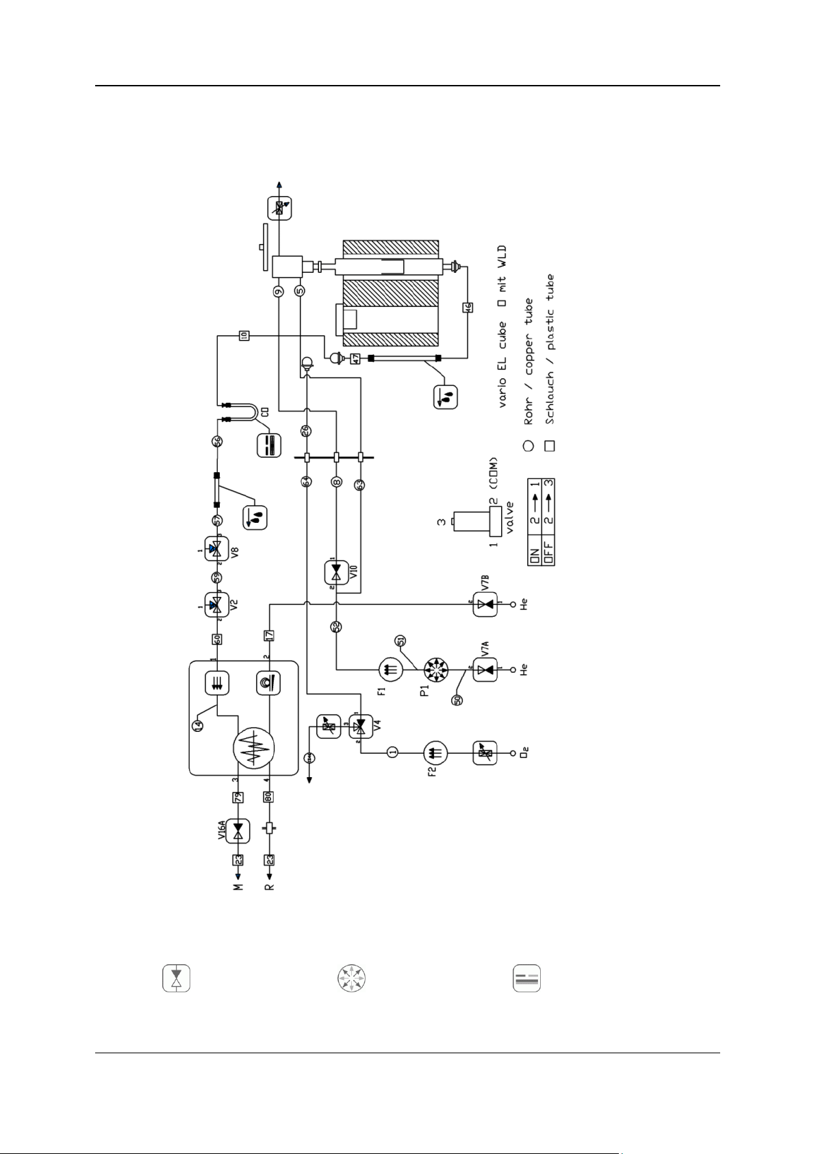
Notes
Two-way valve
Pressure sensor
Gas separation
For a better understanding see also the following illustration (tubing diagram, oxygen determination).
Symbols
The following list names the functional and basic symbols:
Variants Operating Instructions vario EL cube ©Elementar Analysensysteme GmbH

2 - Oxygen determination with TCD 17
Three-way valve
Loop
Measuring cell
Check valve
Heated tube
Sensor
Throttle
Drying
Hose line
Flow controller
Combustion
Copper tube
Flow sensor
Post combustion
Reduction
Pressure contoller
Actuator
Phase
Process
1
The gas mixture of CO and the by-products N2, H2and CH4 flow through the adsorption
column at a temperature of 40 °C.
Thus, the CO is removed quantitatively from the gas stream.
2
As the first component, the by-products unaffected by the adsorption column enter into the
TCD together with the carrier gas helium.
3
The measurement of the N2, H2 and CH4 fractions takes place. The result is ignored
(dummy peak).
4
The adsorption column loaded with CO is heated up to 150°C whereby the CO is desorbed
quickly and flushed by helium into the TCD.
5
A fan cools the adsorption column to cooling temperature of 40 °C and, thus making it ready
for the next analysis sample.
Separation of the reaction gases
Introduction
The following section explains how the individual measuring components in the reaction gas mixture
are separated from each other.
Procedures during separation
The separation of the measuring components is divided into the following phases:
Note
Samples containing fluorine and phosphorus may cause false O results. Fluorine my cause damages
in the instrument, particulary at the quartz parts. Alkaline, earth alkaline and sulfurous samples have
to be loaded with a 1:1 mixture of hexamethylentetramine and ammonia chloride. When measuring
heavy alkaline/earth alkaline samples the pyrolysis tube will corrode.
Detection
Introduction
The method of detection is described under Detection of measuring components and evaluation of
the measuring signal in the vario EL cube operating instructions.
Variants Operating Instructions vario EL cube ©Elementar Analysensysteme GmbH

2 - Oxygen determination with TCD 18
Variations relevant for the oxygen determination
Legend:
1 Ash finger (used as protection tube)
2 Ash crucible
3 Graphite felt (10 mm)
4 Carbon black (55 mm)
5 Support rod (110 mm)
6 Quartz chips, coarse (2-4 mm)
7 Quartz wool (2 mm)
O integration
After the dummy peak integration has been finished, the following is possible:
Directly heat-out the CO collected on the adsorption column (approx. 260°C).
Heat-up the adsorption column to an "interim temperature" (approx. 60°C) in order to
separate hydrocarbons from the CO if necessary.
Prior to the start of the CO integration, another autozero alignment is carried out.
The O integration has been finished if the process time "peak anticipation time for O" (factory set
to 150 sec) has expired, and the dector signal is smaller than the cut-off threshold "O peak"
(defined internally).
Tube fillings
Requirements:
Before starting work, the following requirements must be met:
All quartz and glass components must be cleaned before their usage. Clean the tubes from
fingerprints by means of a suitable solvent (e.g. acetone) before installing. Otherwise there is a
risk of crystallization which will lead to premature ageing of the quartz.
Use chemicals necessary for the tube fillings only in the appropriate quality. Delivery directly from
the instrument manufacturer.
Safety instruction
Strictly observe the safety instruction "Filling reaction tubes" under Warning notes during operation
(on page 11).
Filling of the quartz pyrolysis tube (crack tube) for O determination
The arrangement of the filling must be carried out as shown in the following illustration.
The insert in the core of the tube contains the solid pyrolysis residue as well as the melted silver from
the silver boats.
Variants Operating Instructions vario EL cube ©Elementar Analysensysteme GmbH

2 - Oxygen determination with TCD 19
Removal of traces of moisture and other contaminations from the carrier gas
Legend:
1 Cotton
2 NaOH
3 Quartz wool (10 mm)
4 Sicapent®
5 Gas inlet
For gas drying insert commercial cleaning cartridges between gas delivery point and instrument, if
necessary.
Humid carrier gas causes a CO base which will be collected as a blank on the adsorption column.
Filling the NaOH absorption tube
The following picture shows the filling of the absorbtion tube:
Proceed as follows:
Fill the tube with NaOH (on carrier) and with Sicapent® (identical fill heights).
Close the tube ends with cotton.
Insert the NaOH tube into the already mounted clamps at the left side of the combustion furnace.
Modification to O Mode
Scope of the modification kit for oxygen determination
Variants Operating Instructions vario EL cube ©Elementar Analysensysteme GmbH
All parts necessary for the tube modification are included in the O upgrade kit for detecting oxygen
with TCD and are labeled with numbers.
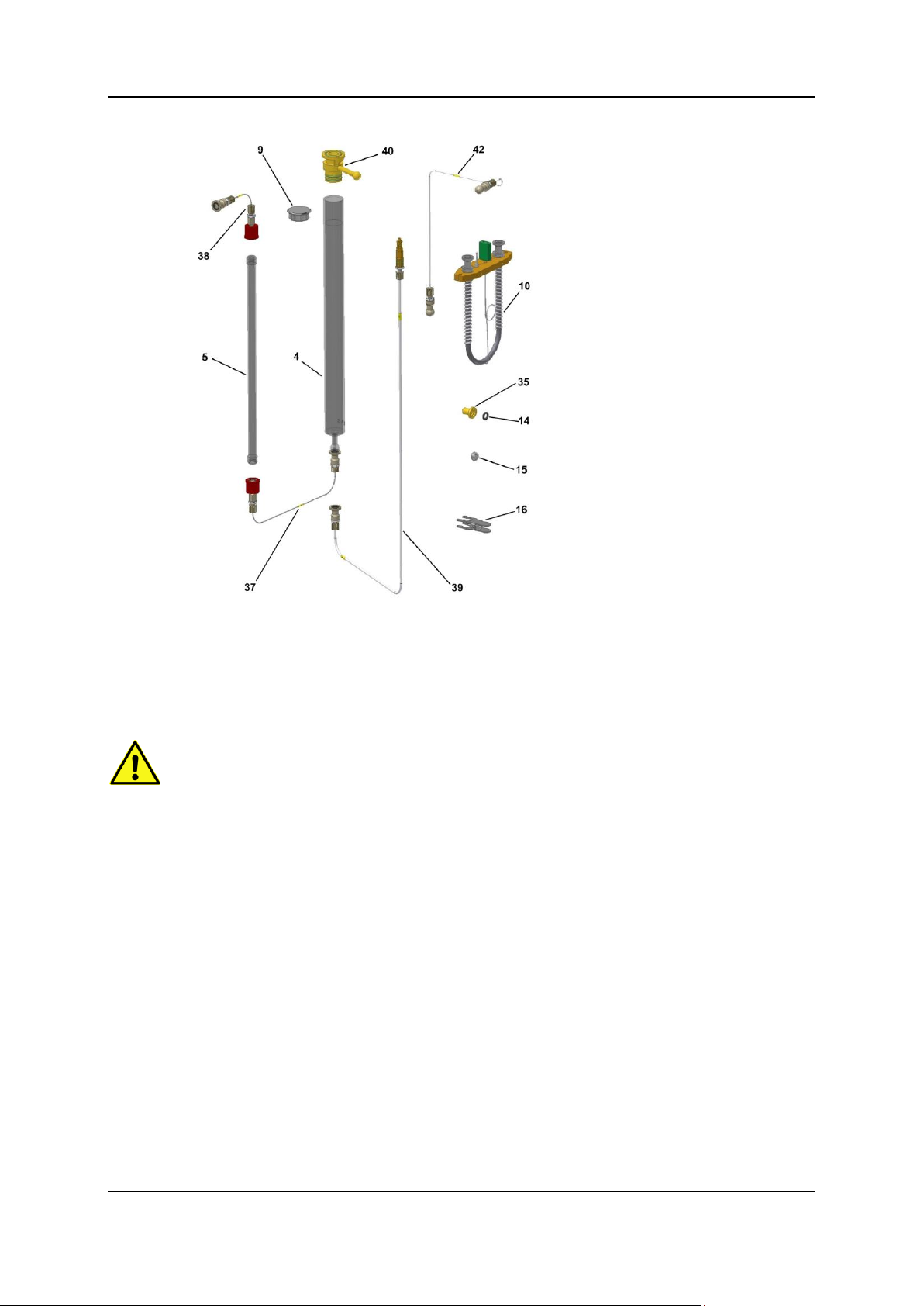
2 - Oxygen determination with TCD 20
Legend:
4 Pyrolysis tube
5 Glass tube
9 Insulation plug
10 Adsorption column
14 Quad ring, black
15 Ball
16 Ground-in clamp
35 Pan, closed
37 Tube no. 46
38 Hose line no. 47
39 Hose line no. 48
40 Combustion tube flange
42 Hose line no. 10
Safety instruction
Note
Process
Phase 1: Removal of components not needed
The following parts are also part of the kit but are not pictured.
Sheath tube
Ash crucible
D-sub-adapter
Software update CD.
Strictly observe the safety instruction "Gas pressure" under Warning notes during operation (on
page 11).
To remove/install the tubes proceed as described in chapter Removing standard reaction tubes of the
vario EL cube main operating instructions.
The modification is divided into the following phases:
Removal of components not needed
Modification
Installation of components necessary for the O operation
Proceed as follows:
Before starting the installation of the pyrolysis tube, remove the components as following listed:
O2 supply line
Variants Operating Instructions vario EL cube ©Elementar Analysensysteme GmbH
2 - Oxygen determination with TCD 21
Quartz glass bridge
Combustion tube
Reduction tube with plug
Tube no. 108 (heated)
These components are not needed for the oxygen operation mode.
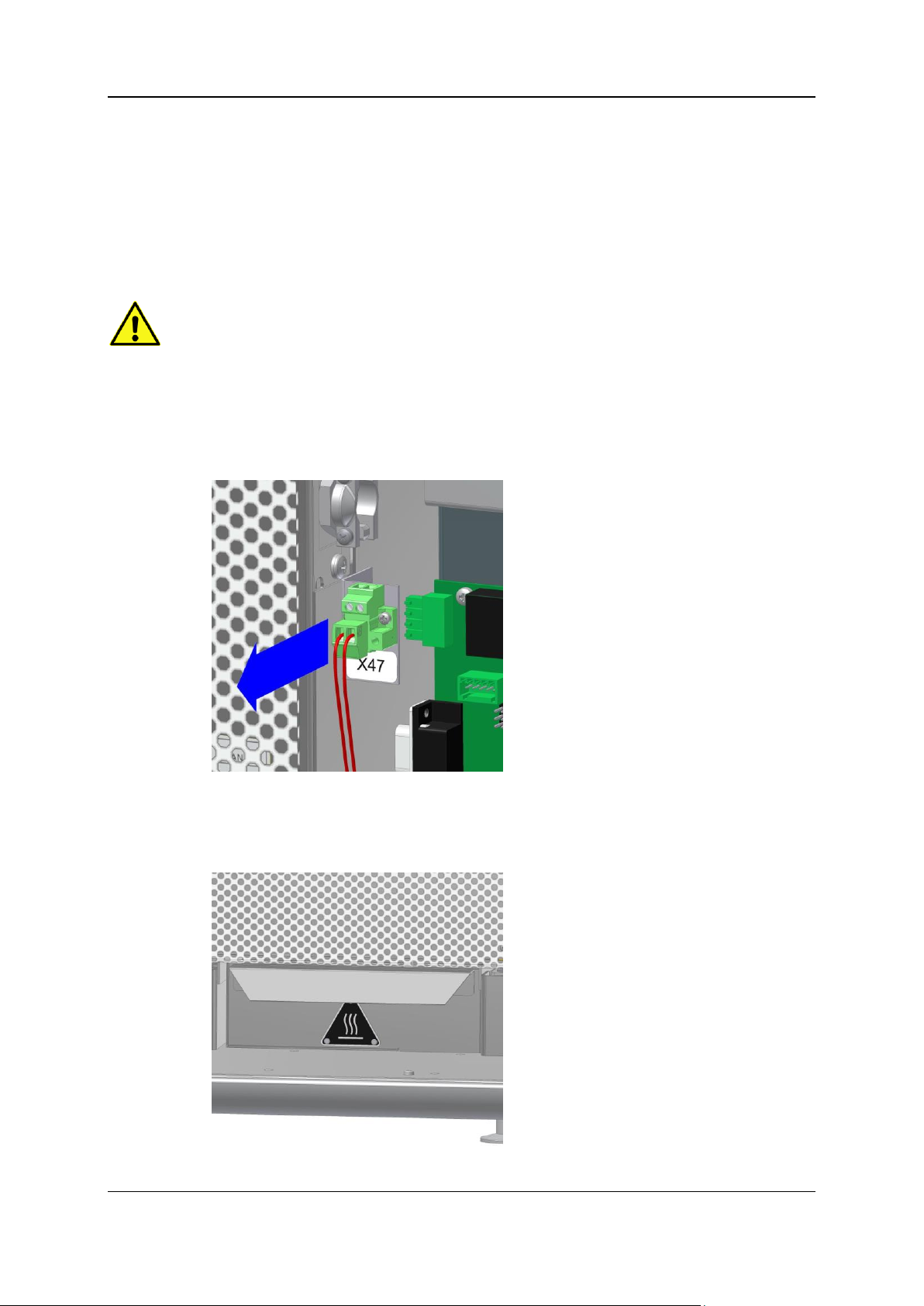
Phase 2: Modification
Safety instruction
Strictly observe the safety instruction "Hot instrument parts" under Warning notes during operation
(on page 11).
Proceed as follows:
Open the right side door.
Loosen the plug of the heating cartridge holder (X47) and close the right side door.
Note: For a modification to a mode with quartz glass bridge, the plug of the heating cartridge
holder has to be plugged back into socket X47!
Open the front door.
Remove the heat protection below the furnace.
Variants Operating Instructions vario EL cube ©Elementar Analysensysteme GmbH
2 - Oxygen determination with TCD 22
If not already done, loosen all connections to the reaction tubes.
Pull the furnace out of the instrument.
Remove the ground-in clamps, the quartz glass bridge and the combustion tubes.
Phase 3: Installation of components necessary for the O operation
The numbers shown in parentheses refer to the illustration above "Scope of the upgrade kit".
Proceed as follows:
Insert the pyrolysis tube (4) which is filled and mounted with the combustion tube flange (40) into
the right tube of the furnace.
Note:
The top o-ring used for sealing of the bayonet catch has to be checked frequently for mechanical
damages and replaced if necessary.
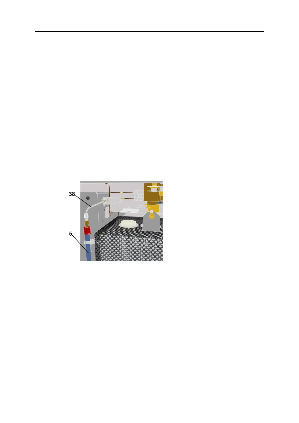
Push carefully the filled absorption tube (5) into the clamps located at the left side of the furnace.
Observe that the NaOH layer is on the bottom (gas inlet).
Connect the pyrolysis tube outlet with the NaOH tube inlet by means of the tube No. 46 (37).
Push the furnace back into the instrument.
Connect the outlet of the NaOH absorption tube (top) with tube no. 47 (38). Connect the other
end of the tube by means of the ground-in clamp to the ball of hose line no. 10 located at the
instrument.
For that purpose the ball joint has to be turned to 90° and pushed into the appropriate clamp.
Close the left heating tube by means of the insulation plug (9).
Fasten the pyrolysis tube to the ball valve by means of the bayonet catch. The centering bolt has
to be within the notch of the centering angle (lock against rotation).
Close the tube 26 with the ball (15) and ground-in clamp (16).
Close the open tube at the combustion tube flange with the pan (35).
Exchange the CO2 adsorptions column against the CO adsorption column (10).
Proceed as described under Removing/installing and conditioning the adsorption column of the
vario EL cube main operating instructions.
Connect tube no. 10 (42) with the CO column (10) by means of the ground-in clamp.
The modification has now been completed and the instrument is ready for the O determination in
routine operation.
Variants Operating Instructions vario EL cube ©Elementar Analysensysteme GmbH

2 - Oxygen determination with TCD 23
View after the modification has been completed
The following picture shows the oxygen mode after the modification has been completed.
Conditioning the pyrolysis tube
Introduction
The following section describes in detail how to condition the pyrolysis tube.
Prior to routine analysis the pyrolysis tube has to be conditioned. For this purpose flush the carbon
black filling for approx. 12 hours at 1,170°C under helium in the instrument; subsequently, analyze 5
samples polyethylene (weight 8 mg).
Conditioning the pyrolysis tube
Proceed as follows:
Turn on PC and printer. Wait until the boot process has been finished.
Switch on the instrument.
The instrument performs now a reference run of the ball valve and autosampler.
Switch on the operating gas. Set the intake pressure at the delivery point to 0.5 bar.
Open the gas connection to the NaOH tube.
Connect tube no. 48 with the outlet of the pyrolysis tube. Lead the end of the hose line through
the crack in the door into the open. The front door has to be closed.
Variants Operating Instructions vario EL cube ©Elementar Analysensysteme GmbH

2 - Oxygen determination with TCD 24
Note
Connect th end of tube no. 48 with the furnished black hose (Article No. 03 651 010, 25 m) and
lead the gases resulting from conditioning (e.g. H2S, water vapor) into an exhaust hood or into
the open.
Start the instrument software and select in the menu System > Mode the operation mode "O",
option "TCD" checked.
Leave the mode menu by clicking OK; if necessary a new initialization of the instrument occures.
To heat up the furnace call the menu Options > Settings > Parameters. Set the temperature of
oven 1 to 1170 °C.
Note: The modification of the instrument parameters is only possible with the appropriate
access rights.
After reaching the setpoint temperture (after approx. 1.5 hours) heat-out the pyrolysis tube for
another 12 hours (over night).
Remove tube no. 48.
Connect the 25 m long exhaust hose with the outlet at the instrument rear.
Close the gas connection at the NaOH tube and adjust the intake pressure at the delivery point
until the PC displays a pressure of approx. 1.2 bar.
Analyze 5 samples polyethylene each 8 mg (conditioning) and 10 samples benzoic acid each
approx. 1.5 mg (stability test) after the flush process.
Now the instrument is ready for the O determination in routine operation.
Samples containing fluorine and phosphorus may cause false O results. Fluorine my cause damages
in the instrument, particulary at the quartz parts. Alkaline, earth alkaline and sulfurous samples have
to be loaded with a 1:1 mixture of hexamethylentetramine and ammonia chloride. When measuring
heavy alkaline/earth alkaline samples the pyrolysis tube will corrode.
Changing of the pyrolysis crucible
Changing of the pyrolysis crucible
In addition to the common maintanance work, the replacement of the pyrolysis crucible for oxygen
determination will be described here. The crucbile has to be emptied after approx. 80 samples, if you
work with the polyethylene additive.
Safety instruction
Strictly observe the safety instruction "Hot instrument parts" under Warning notes during operation
(on page 11).
Proceed as follows:
Cool the furnace down to approx. 600°C.
Open the front door.
Initiate a pressure drop by clicking the menu command Options > Maintenance > Replace
parts.
After completion of the pressure drop procedure detach the ground-in clamp at the NaOH tube
outlet.
Open the bayonet catch at the ball valve.
Pull the furnace out of the instrument.
Pull the combustion tube flange out of the pyrolysis tube.
Variants Operating Instructions vario EL cube ©Elementar Analysensysteme GmbH

2 - Oxygen determination with TCD 25
Pull the sheath tube and the crucible with the tongs out of the pyrolysis tube.
Empty the crucible.
Install...
... either the emptied crucible once again, or
... a new crucible immediately after the filled crucible has been removed. This has to be
conditioned by running 5 samples polyethylene (weight 8 mg).See Conditioning the
pyrolysis tube TCD (on page 23).
Push the furnace into the instrument. Observe that the ball valve adaptor is centered in the
bayonet catch.
Close both the bayonet catch at the ball valve and the ground-in ball-and-socket joint at the
NaOH tube.
Leave the "Replace part" dialog by clicking Finish.
Flush the apparatus for approx. 1 hour and set the furnace temperature back to 1,170 °C.
Wait until the PC display of the baseline of the detector is stable.
The flushing time depends on the amount of atmospheric nitrogen penetrated into the apparatus
during the replacement of the tube insert.
In unpropitious cases, the flushing procedure can last up to 45 minutes.
Establishing of the analysis readiness
Establishing of the analysis readiness
Proceed as follows:
Turn on PC and printer and wait until the boot process has been completed.
Switch on the instrument.
The instrument performs now a reference run of the ball valve and carousel.
Switch on the operating gases.
Launch the operating software.
Open the "Analysis mode" dialog in the operating software by selecting System > Mode. Select
the desired operation mode ("O" for oxygen).
Set the detector mode to "TCD".
Leave the mode dialog by clicking OK; a re-initialization of the system takes place.
Defining test/standard substances
By means of the menu Options > Settings > Standards you can see whether the test substances to
be used are stored there.
A description how to define a new and/or modify an existing standard is given under Edit standard
samples in the vario EL cube operating instructions.
If no modifications have been carried out in the standard samples dialog, leave it by clicking Close,
otherwise by clicking Save followed by Close.
Note:
If the value "0" stands for the element content percentage of a test substance, this test substance will
be ignored for the respective element during calibration and/or during the calculation of the daily
factor.
Variants Operating Instructions vario EL cube ©Elementar Analysensysteme GmbH

2 - Oxygen determination with TCD 26
Routine operation
For a description of the particular software terms refer to Menu and dialog descriptions in the vario EL
cube operating instructions.
Setting the furnace temperature
Proceed as follows:
Open the "Device parameter" dialog in the operating software by selecting Options > Settings >
Parameters.
Check and/or enter the following oven temperature (oven 2 is not needed here):
For operating mode O: Pyrolysis tube (oven 1): 1170 °C
Leave the dialog by clicking OK (or by clicking Cancel). The modules are now re-initialized if
necessary.
In the sataus view you can observe how the temperature of oven 1 increases.
The heat-up time takes approx. 60 minutes.
For an optimum lifetime of the instrument, the tubes and the consumables, we recommend to
leave the instrument turned on.
Once the setpoint temperature has been reached the instrument is ready to measure.
Notes on performing calibration
Background
The calibration serves for creating a correlation between the measured peak area of the individual
element and the concentration of the element in the sample.
This correlation is established via the so called calibration coefficients which are calculated from the
calibration run.
Checking the calibration
Prior to the beginning of each series of measurements, it has to be checked if the instrument is
calibrated.
Proceed as follows:
Open the "Calibration coefficients" dialog in the operating software by selecting Math. >
Coefficients.
The coefficients dialog allows manual input of the calibration coefficients as well as of the limit
values of the corresponding calibration range.
Sample weights
In practice, the following sample sequence has proven for a measuring range of 0.03 mg to 2.0 mg O:
10 conditioning samples of benzoic acid, approx. 2 -3 mg each for O conditioning
3 conditioning samples, 0.1-0.15 mg each
27 samples with sample weights as follows:
0.1 - 0.1 - 0.15 - 0.2 - 0.25 - 0.3 - 0.4 - 0.5 - 0.6 - 0.7 - 0.8 - 0.9 - 1.0 - 1.5 - 2.0 - 2.5 - 3.0 - 4.0 -
4.5 - 5.0 - 5.5 - 6.0 - 6.5 - 7.0 - 7.5 - 8.0 mg.
If the measuring range is to be extended, the following sample weights can be added:
Benzoic acid 9 - 10 - 12 - 14 - 16 - 18- 19 mg.
Thus, a measuring range up to 5 mg absolute oxygen will be covered.
Variants Operating Instructions vario EL cube ©Elementar Analysensysteme GmbH

2 - Oxygen determination with TCD 27
Polyethylene additive
Sample weight
polyethylene
Blank value area
8,014
504
8,03
508
8,04
505
8,006
502
The poylethylene additive improves the absolute accuracy and/or recovery. In practise an addition of
approx. 8.0 mg per sample has proven to be of value.
Attention should be paid to:
Conditional of manufacturing, polyethylene contains minor concentrations of oxygen (approx. 0.2 ...
0.4%).
Prior to a measuring series start, especially during the calibation, the blank value of the used
polyethylene has to be determined. Enter the blank value area in the column "O-blank", e.g. the mean
value from 4 or 5 measurements.
Example:
The mean value of the blank value area is 505 and has to be entered for the analysis samples /
calibration samples in the column "O-blanks".
To ensure a correct calculation of the calibration select the manual calculation under Options >
Settings > Calculation > Blank Value Determination > Manual Input.
Subsequently, start the calcuation of the calibration under Math. > Calibrate, where the mathematical
treatment of the blank values is done automatically.
Oxygen analyses in routine operation
Sample sequence
In routine operation, the following sample sequence (if necessary with PE additive of each 8 mg per
sample) is recommended:
3 x conditioning sample (approx. 2.0 mg benzoic acid)
4 x benzoic acid (approx. 2.0 mg) for the determination of the daily factor
20 real samples
3 x benzoic acid (approx. 2.0 mg) for the monitoring of the daily factor
20 real samples
3 x benzoic acid (approx. 2.0 mg) etc.
The sample weight values can be entered either directly from a connected balance or manually via
the keyboard.
Parameter menu settings
The instrument has factory set analysis parameters for test substances defined in the standards
menu (e.g. acetanilide, benzoic acid).
Note: The modification of the instrument parameters is only possible with the appropriate
access rights.
Variants Operating Instructions vario EL cube ©Elementar Analysensysteme GmbH

2 - Oxygen determination with TCD 28
Temperature parameters
Parameter
Meaning
Factory setting
Oven 1 (pyrolysis tube) in O
mode
Pyrolysis tube
1,170 °C
Furnace 2
not used
Ads. col. standby
Adsorption temperature of the CO column
40 °C
Adsorp. column, Cooling temp.
At the end of analysis, the program waits until
column temperature drops below this value.
50 °C
Parameter
Meaning
Factory setting
Flushing time
Time in which the blind hole of the ball valve
is flushed, so the atmospheric oxygen will be
removed.
10 s
Integrator reset delay dummy
This time comes into effect for the first peak
of the respective operation mode after the
sample is fed and prevents the ensuing
detector instabilities from being jointly
integrated.
2 sec, operating
mode O
Integrator reset delay peak O
See above.
2 s
Desorpt. mid.
1 s
Parameter
Meaning
Factory setting
Autozero delay dummy
On starting up, the autozero alignment is
carried out after the autozero delay.
2 sec, operating
mode O
Autozero delay O
See above.
2 s
Peak Anticipation dummy
The anticiaption time comes into effect after
the integrator reset. During this time the
integrator waits for a measuring peak. If the
measuring peak does not appear within this
time, the integration is concluded and the
next analysis is started.
250 s
Peak anticipation O
See above.
150 s
Desorpt. O
Corresponds to the desorption temperature of
the column in O/TCD mode.
260 °C
Desorpt. midtemp.
40 °C
The following table shows the pre-set temperatures and explains the meaning of the parameters:
Time parameters
The following table shows the pre-set times and explains the meaning of the parameters:
Further process times and parameters are set via the "Method" dialog:
Variants Operating Instructions vario EL cube ©Elementar Analysensysteme GmbH

2 - Oxygen determination with TCD 29
Application notes for oxygen determination
In this section
Pyrolysis temperature ....................................................................................................................30
Difficult matrices ............................................................................................................................30
Lifetime of the pyrolysis tube .........................................................................................................31
Target group
Personnel with basic knowledge of chemistry and experience with laboratory work, e. g. chemistry
laboratory workers.
Purpose
This section gives additional notes about the application for oxygen determination.
Variants Operating Instructions vario EL cube ©Elementar Analysensysteme GmbH

2 - Oxygen determination with TCD 30
Pyrolysis temperature
Pyrolysis temperature
The method provides correct results only, if the carbon black filling in the pyrolysis tube is operated at
a temperature of at least 1120°C.
In order to set the correct pyrolysis temperature, some samples of benzoic acid (approx. 2,0 mg) are
analyzed with different pyrolysis temperatures.
The optimum temperature value has been reached if the analysis results with the increase of
temperature do no longer vary significantly (< 0.2 % absolute).
Difficult matrices
Organic substances
Samples hard to digest (crackable) may be digested by hyrogen containing, carbon containing and/or
chlorine containing additives like graphite, polyethylene, hexamethylentetramine or NH4Cl .
The additives must be dry and must not contain any oxygen.
Substances containing fluorine
Substances containing fluorine react with the quartz glass forming silicon tetrafluoride and discharge
oxygen which will be measured as CO.
Additives, containing blank values
Partially, the recommended additives are hygroscopic and therefore they will deliver a oxygen blank
value.
This blank value has to be determined in order to be able to correct the analysis results.
Procedure example:
6 x analysis of 15 - 16 mg additive.
If the results are stable, compute the mean value from samples 4, 5 and 6 and then subtract this
value from all samples which have been weighed in with an additive. (Input in column "Blank")
Measuring alkaline/earth alkaline samples
When measuring alkaline/earth alkaline samples the pyrolysis tube will corrode and its lifetime will be
shortened.
The system pressure will bloat the tube until it eventually bursts.
This may lead to destruction of the furnace.
It is recommended to check the tube regulary for bloatings and to replace it in time with original spare
parts.
Notes on matrix dependency
Due to the nature of pyrolysis, differences in recovery may occur, depending on the molecular
structure and bond type of the oxygen. This fact has to be considered when very precise
measurements are required.
To guarantee the absolute accuracy of the measuring results, it is recommended to use standard
substances for calibration and daily factor determination which have the same bond type like oxygen.
For general measurements of unknown substances use the average daily factor of 2 measured
standards.
Variants Operating Instructions vario EL cube ©Elementar Analysensysteme GmbH

2 - Oxygen determination with TCD 31
The following table shows some examples for determining the daily factor and/or the calibration:
Analysis of ...
Calibration and/or daily factor substance
amino acids
Glutamic acid
nitrates
KNO3, AgNO3
Coal
commercially available coal standard
general applications,
unknown substance classes
calibration with benzoic acid;
daily factor averaged from benzoic acid and acet anilide
Lifetime of the pyrolysis tube
Lifetime of the pyrolysis tube (and/or the carbon black filling)
Permanent flushing the tube with carrier gas has proven to be the most efficient procedure. The tube
can be stored for example in an exsiccator during longer breaks, and then used again.
Note that under the existing measuring conditions the quality of the quartz glass is very important.
Under the prevailing circumstances use only original spare parts from Elementar to avoid the
destruction of the furnace.
If the pyrolysis tube is used again, a conditioning of the tube prior to the actual measurements shall
be done.
Flush for approx. 2 hours with carrier gas at 1170 °C
Measurement of 5 samples polyethylene and 10 samples benzoic acid each approx. 2 mg.
Only if the carbon black filling in the pyrolysis tube has decreased significantly, the installation of a
newly filled pyrolysis tube with subsequent flushing and conditioning is recommended.
Variants Operating Instructions vario EL cube ©Elementar Analysensysteme GmbH

2 - Oxygen determination with TCD 32
Additional error messages in O mode
Error
Possible causes
Corrective action
Wide peaks with test
substances
Contaminated carbon black
filling in the pyrolysis tube.
Replace pyrolysis tube.
Used up carbon black filling in
the pyrolysis tube.
Replace pyrolysis tube.
Pyrolysis crucible
contaminated.
Replace and/or empty crucible by more
than 80 samples.
Wide peaks with
samples
Indicates to uncompleted
pyrolysis.
Add additives as decribed under
Difficult matrices (on page 30).
Wide peaks
Contamination of the CO
adsorption column.
Bake out CO adsorption column.
Measuring values vary
Contaminated carbon black
filling in the pyrolysis tube.
Replace pyrolysis tube.
Used up carbon black filling in
the pyrolysis tube.
Replace pyrolysis tube.
Pyrolysis crucible
contaminated.
Replace and/or empty crucible by more
than 80 samples.
Leakages
Carry out leak test, eliminate leak if
necessary.
Varying boat blank values.
Run at least 20 blank samples with
empty silver boats.
Peak end error
Sample weight too high.
Reduce sample weight.
Element content of sample
too high.
Increase peak end threshold of dummy
peak.
The following table lists possible error messages, explaining the causes of the errors and giving tips
for troubleshooting:
Variants Operating Instructions vario EL cube ©Elementar Analysensysteme GmbH

Target group
In this chapter
Analytical characteristics and technical specifications ...................................................................34
Substance digestion and functional diagram .................................................................................34
Detection .......................................................................................................................................38
Tube fillings ...................................................................................................................................38
Modification to O Mode ..................................................................................................................40
Conditioning the pyrolysis tube ......................................................................................................46
Changing of the pyrolysis crucible .................................................................................................47
Establishing of the analysis readiness ...........................................................................................48
Notes on performing calibration .....................................................................................................49
Oxygen analyses in routine operation ...........................................................................................50
Application notes for oxygen determination ...................................................................................52
Additional error messages in O mode ...........................................................................................55
C H A P T E R 3
Oxygen determination with NDIR
Personnel involved with the instrument.
Purpose
This section describes the special features of the oxygen determination with NDIR.
Variants Operating Instructions vario EL cube ©Elementar Analysensysteme GmbH

3 - Oxygen determination with NDIR 34
Analytical characteristics and technical specifications
Analytical characteristic
Comments
Analysis method
Oxygen determination by pyrolysis of the samples, specific
detection of the measuring component CO with NDIR.
Detector
NDIR detector
Sample weight/sample volume
Approx. < 1 to 10 mg depending on the substance.
Working range
(depending on kit and measuring
mode)
O: 0.005 - 2 mg
Precision / standard deviation
<0,2 % with benzoic acid (approx. 2 mg)
Duration of analysis
(depending on element content
and sample weight)
O: 8 - 15 min
Calibration
Linear and non-linear curve adjustment; total work range.
Data storage and data output
Storage on hard disk or external storage media.
LIMS transfer possible.
Data output to screen and printer.
Reference value
Technical specifications
Supply gases
Forming gas N2/H2 95/5 (95 % N2, 5 % H2), water free, CO2 free, O2
free
Consumption of supply gases
Per analysis approx. 1.4 to 2.6 liters.
Phase
Process
1
The substance to be analyzed is digested in reductive atmosphere at a temperature of
approx. 1,150 °C (1,170 °C) by means of pyrolysis (cracking).
2
For the digestion weigh in the sample into silver boats (for liquid samples silver capsules are
available). The folded boat is thrown into the quartz glass pyrolysis tube by means of an
autosampler.
3
The oxygen containing radicals formed in the pyrolysis tube are converted quantitatively at a
carbon contact (special carbon black) into carbon monoxide (Boudouard equilibrium).
Analytical characteristics
The following table explains the analytical characteristics:
Technical specifications
The following table contains the technical specifications of the gas supply:
Substance digestion and functional diagram
Introduction
The following section explains:
Which procedures in the pyrolysis tube of the furnace are processed.
How the reaction mixture is prepared for the detection.
Processes during substance digestion and preparation of the reaction gas mixture
Substance digestion and preparation of the reaction gas mixture is divided into the following phases:
Variants Operating Instructions vario EL cube ©Elementar Analysensysteme GmbH

Variants Operating Instructions vario EL cube ©Elementar Analysensysteme GmbH
3 - Oxygen determination with NDIR 35
4
Acidic pyrolysis products like e.g. H2S, HCN, HCl etc. are absorbed at NaOH by means of
an absorption tube which is downstream of the pyrolysis tube.
5
Usually, water is set free during the reaction of NaOH with an acidic medium. Therefore, the
gas mixture is dried once again after the NaOH layer.
6
Other pyrolysis products like e.g. N2 and CH4 are led to a measuring system together with
the carbon monoxide to be detected.
Since the NDIR detector does only respond to CO, foreign gases, like e.g. N2 and CH4 does
not have to be separated.

3 - Oxygen determination with NDIR 36
Oxygen determination with single NDIR detector CO
For a better understanding see also the following illustration (tubing diagram, oxygen determination).
Variants Operating Instructions vario EL cube ©Elementar Analysensysteme GmbH

3 - Oxygen determination with NDIR 37
Oxygen determination with dual NDIR detector CO/SO2
Two-way valve
Pressure sensor
Gas separation
For a better understanding see also the following illustration (tubing diagram, oxygen determination).
Symbols
The following list names the functional and basic symbols:
Variants Operating Instructions vario EL cube ©Elementar Analysensysteme GmbH

3 - Oxygen determination with NDIR 38
Three-way valve
Loop
Measuring cell
Check valve
Heated tube
Sensor
Throttle
Drying
Hose line
Flow controller
Combustion
Copper tube
Flow sensor
Post combustion
Reduction
Pressure contoller
Actuator
Detection
Introduction
The detection of the measuring component CO is carried out with a CO specific NDIR detector.
Depending on the individual application, either the single NDIR detector CO or the dual NDIR detector
CO/SO2 is used. The resulting differences are described in this chapter at the relevant positions.
O integration
After the analysis start, first the auto zero adjust of the NDIR takes place.
Subsequently, insertion of the sample takes place.
Shortly after the sample feeding the CO peak starts and the peak integration with it.
The O integration has been finished if the process time "peak anticipation time for O" (factory set to
150 sec) has expired, and the dector signal is smaller than the cut-off threshold "O peak" (defined
internally).
To secure an optimum accuracy of the measuring results, the cut-off threshold is set very low.
Tube fillings
Requirements:
Before starting work, the following requirements must be met:
All quartz and glass components must be cleaned before their usage. Clean the tubes from
fingerprints by means of a suitable solvent (e.g. acetone) before installing. Otherwise there is a
risk of crystallization which will lead to premature ageing of the quartz.
Use chemicals necessary for the tube fillings only in the appropriate quality. Delivery directly from
the instrument manufacturer.
Safety instruction
Strictly observe the safety instruction "Filling reaction tubes" under Warning notes during operation
(on page 11).
Variants Operating Instructions vario EL cube ©Elementar Analysensysteme GmbH

3 - Oxygen determination with NDIR 39
Filling of the quartz pyrolysis tube (crack tube) for O determination
Legend:
1 Ash finger (used as protection tube)
2 Ash crucible
3 Graphite felt (10 mm)
4 Carbon black (55 mm)
5 Support rod (110 mm)
6 Quartz chips, coarse (2-4 mm)
7 Quartz wool (2 mm)
Legend:
1 Cotton
2 NaOH
3 Quartz wool (10 mm)
4 Sicapent®
5 Gas inlet
The arrangement of the filling must be carried out as shown in the following illustration.
The insert in the core of the tube contains the solid pyrolysis residue as well as the melted silver from
the silver boats.
Removal of traces of moisture and other contaminations from the carrier gas
For gas drying insert commercial cleaning cartridges between gas delivery point and instrument, if
necessary.
Humid carrier gas causes a CO base which will be collected as a blank on the adsorption column.
Filling the NaOH absorption tube
The following picture shows the filling of the absorbtion tube:
Proceed as follows:
Fill the tube with NaOH (on carrier) and with Sicapent® (identical fill heights).
Variants Operating Instructions vario EL cube ©Elementar Analysensysteme GmbH
Close the tube ends with cotton.
Insert the NaOH tube into the already mounted clamps at the left side of the combustion furnace.

3 - Oxygen determination with NDIR 40
Modification to O Mode
Legend:
4 Pyrolysis tube
5 Glass tube
9 Insulation plug
12 Pan UNF ¼"
13 Blind plug UNF 1/4"
14 Quad ring, black
15 Ball
16 Ground-in clamp
17 RS 232 module
19 Hose line no. 37
20 Hose line no. 29
21 Screw M3x6
22 Serrated washer, 3.2
24 Guidance angle
25 Screws M4x8
35 Pan, closed
36 Hose seal 1/16"
37 Tube no. 46
38 Hose line no. 47
39 Hose line no. 48
40 Combustion tube flange
42 Hose line no. 10
Scope of the modification kit for oxygen determination
All parts necessary for the tube modification are included in the O upgrade kit for detecting oxygen
with NDIR and are labeled with numbers.
With the new delivery of a complete system the RS 232 module and the NDIR detector are already
installed in the instrument (NDIR: left instrument side, behind the left side door, RS 232 module: right
instrument side, electronics).
The following parts are also part of the kit but are not pictured.
Sheath tube
Ash crucible
D-sub-adapter
Software update CD.
Safety instruction
Strictly observe the safety instruction "Gas pressure" under Warning notes during operation (on
page 11).
Note
To remove/install the tubes proceed as described in chapter Removing standard reaction tubes of the
vario EL cube main operating instructions.
Process
The modification is divided into the following phases:
Removal of components not needed
Modification
Installation of components necessary for the O operation
bridge the adsorption column
Variants Operating Instructions vario EL cube ©Elementar Analysensysteme GmbH

3 - Oxygen determination with NDIR 41
Installation of components necessary for the O operation, continued
Phase 1: Removal of components not needed
Proceed as follows:
Before starting the installation of the pyrolysis tube, remove the components as following listed:
O2 supply line
Heat cover under the furnace
Quartz glass bridge
Reduction tube with plug
Tube no. 108 (heated)
These components are not needed for the oxygen operation mode.
Phase 2: Modification
Safety instruction
Strictly observe the safety instruction "Hot instrument parts" under Warning notes during operation
(on page 11).
Proceed as follows:
Turn off the instrument and pull the power supply plug.
Open the right side door.
Loosen the plug of the heating cartridge holder (X47) and close the right side door.
Note: For a modification to a mode with quartz glass bridge, the plug of the heating cartridge
holder has to be plugged back into socket X47!
Open the front door.
Variants Operating Instructions vario EL cube ©Elementar Analysensysteme GmbH

3 - Oxygen determination with NDIR 42
Remove the heat protection below the furnace.
If not already done, loosen all connections to the reaction tubes.
Pull the furnace out of the instrument.
Remove the ground-in clamps, the quartz glass bridge and the combustion tubes.
Open the left side wall.
Fasten the guidance angle (24) with screws M4x8 (25).
Loosely insert two screws M4x8 (25) into the tap holes, so that the distance between screw
heads and sheet is still 2 mm.
Mount the NDIR photometer into the analyzer as displayed below: Push the two designated
recesses over the loosely inserted screws and then shift the photometer to the left up to the stop.
Make sure the upper lug of the NDIR photometer will snap into the guidance angle.
Now fasten the photometer by fixing both screws.
Variants Operating Instructions vario EL cube ©Elementar Analysensysteme GmbH

3 - Oxygen determination with NDIR 43
Connect the photometer as follows:
(A) Cable #50 to RS232 module
(B) Cable #53 (internal IR)
(C) Cable #51 (power supply)
Connect the pre-installed cable no. 51 (C) with the double-pole plug on the IR board.
Connect the pre-installed data cable no. 50 (A) with the 9 pin D-SUB plug on the RS232 module
of the IR photometer. In case the plug of the data cable does not fit to the RS232 module
connector, use the enclosed "D-SUB adaptor" (part no. 05 001 961).
Open the right side door.
Attach the RS232 module (17) on the BCB board (JP5) by means of the four screws M3x6 and
connect it (COM2).
Connect the pre-installed data cable no. 50 to the RS232 module just installed.
Remove the plugs from the rear wall.
Variants Operating Instructions vario EL cube ©Elementar Analysensysteme GmbH

3 - Oxygen determination with NDIR 44
Remove the connecting piece of the measure gas outlet using a 7mm open jawed wrench.
Lead tube no. 37 (19) from inside to outside through the hole (IR inlet) and connect it to the
measure gas outlet using a knurled reducing nipple.
Lead the outlet hose line of the NDIR photometer no. 29 (20) from inside to outside through the
hole (IR outlet).
The double nipple connector at the end of the hose line no. 29 (20) is used to connect the on-site
waste gas line.
CAUTION: Follow the notes about discharging the waste gases into the open or into a vent
in the vario EL cube main operating instructions!
Close the left and right side door.
Phase 3: Installation of components necessary for the O operation
The numbers shown in parentheses refer to the illustration above "Scope of the upgrade kit".
Proceed as follows:
Insert the pyrolysis tube (4) which is filled and mounted with the combustion tube flange (40) into
the right tube of the furnace.
Note:
The top o-ring used for sealing of the bayonet catch has to be checked frequently for mechanical
damages and replaced if necessary.
Push carefully the filled absorption tube (5) into the clamps located at the left side of the furnace.
Observe that the NaOH layer is on the bottom (gas inlet).
Connect the pyrolysis tube outlet with the NaOH tube inlet by means of the tube No. 46 (37).
Push the furnace back into the instrument.
Variants Operating Instructions vario EL cube ©Elementar Analysensysteme GmbH

3 - Oxygen determination with NDIR 45
Connect the outlet of the NaOH absorption tube (top) with tube no. 47 (38). Connect the other
end of the tube by means of the ground-in clamp to the ball of hose line no. 10 located at the
instrument.
For that purpose the ball joint has to be turned to 90° and pushed into the appropriate clamp.
Close the left heating tube by means of the insulation plug (9).
Fasten the pyrolysis tube to the ball valve by means of the bayonet catch. The centering bolt has
to be within the notch of the centering angle (lock against rotation).
Close the tube 26 with the ball (15) and ground-in clamp (16).
Close the open tube at the combustion tube flange with the pan (35).
Remove the ball joint at the open end of tube no. 10 (42) and replace it by the furnished pan (12)
incl. quad ring (14).
Phase 4: Bridge the adsorption column
The adsorption column has to be bridged since it is not be needed in the O/NDIR mode.
Proceed as follows:
Open the left side wall.
Unscrew the retaining screws (1) above the valve rack cover and remove the valve rack cover.
The valve rack is now visible.
Cool down the now exposed components for approx. 15 minutes.
Loosen tube no. 60 from the angled screw coupling at valve MV 2.
Now connect tube no. 60 and hose line no. 10 (42) by means of a ground-in clamp.
Remount the valve cover.
Close the left side door.
Variants Operating Instructions vario EL cube ©Elementar Analysensysteme GmbH

3 - Oxygen determination with NDIR 46
Phase 5: Installation of components necessary for the O operation, continued
Proceed as follows:
Remove the helium gas supply.
Connect the forming gas supply.
Set the intake pressure at the delivery point to show approx. 1150 mbar at the PC pressure
display.
The modification has now been completed and the instrument is ready for the O determination in
routine operation.
View after the modification has been completed
The following picture shows the oxygen mode after the modification has been completed.
Conditioning the pyrolysis tube
Introduction
The following section describes in detail how to condition the pyrolysis tube.
Prior to routine analysis the pyrolysis tube has to be conditioned. For this purpose flush the carbon
black filling for approx. 12 hours at 1,170°C under helium in the instrument; subsequently, analyze 5
samples polyethylene (weight 8 mg).
Conditioning the pyrolysis tube
Proceed as follows:
Turn on PC and printer. Wait until the boot process has been finished.
Switch on the instrument.
The instrument performs now a reference run of the ball valve and autosampler.
Switch on the operating gas. Set the intake pressure at the delivery point to 0.5 bar.
Open the gas connection to the NaOH tube.
Variants Operating Instructions vario EL cube ©Elementar Analysensysteme GmbH

3 - Oxygen determination with NDIR 47
Connect tube no. 48 (see upgrade kit part no. 39) with the outlet of the pyrolysis tube. Lead the
end of the hose line through the crack in the door into the open. The front door has to be closed.
Connect th end of tube no. 48 (see upgrade kit part no. 39) with the furnished black hose (Article
No. 03 651 010, 25 m) and lead the gases resulting from conditioning (e.g. H2S, water vapor) into
an exhaust hood or into the open.
Start the instrument software and select in the menu System > Mode the operation mode "O",
option "IR" checked.
Leave the mode menu by clicking OK; if necessary a new initialization of the instrument occures.
To heat up the furnace call the menu Options > Settings > Parameters. Set the temperature of
oven 1 to 1170 °C.
Note: The modification of the instrument parameters is only possible with the appropriate
access rights.
After reaching the setpoint temperture (after approx. 1.5 hours) heat-out the pyrolysis tube for
another 12 hours (over night).
Remove hose line no. 38 (part no. 29).
Connect the 25 m long exhaust hose (art. no. 03 651 010) with the outlet of the IR at the
instrument rear.
Close the gas connection at the NaOH tube and adjust the intake pressure at the delivery point
until the PC displays a pressure of approx. 1.2 bar.
Analyze 5 samples polyethylene each 8 mg (conditioning) and 10 samples benzoic acid each
approx. 1.5 mg (stability test) after the flush process.
Now the instrument is ready for the O determination in routine operation.
Note
Samples containing fluorine and phosphorus may cause false O results. Fluorine my cause damages
in the instrument, particulary at the quartz parts. Alkaline, earth alkaline and sulfurous samples have
to be loaded with a 1:1 mixture of hexamethylentetramine and ammonia chloride. When measuring
heavy alkaline/earth alkaline samples the pyrolysis tube will corrode.
Changing of the pyrolysis crucible
Changing of the pyrolysis crucible
In addition to the common maintanance work, the replacement of the pyrolysis crucible for oxygen
determination will be described here. The crucbile has to be emptied after approx. 80 samples, if you
work with the polyethylene additive.
Variants Operating Instructions vario EL cube ©Elementar Analysensysteme GmbH

3 - Oxygen determination with NDIR 48
Safety instruction
Strictly observe the safety instruction "Hot instrument parts" under Warning notes during operation
(on page 11).
Proceed as follows:
Cool the furnace down to approx. 600°C.
Open the front door.
Initiate a pressure drop by clicking the menu command Options > Maintenance > Replace
parts.
After completion of the pressure drop procedure detach the ground-in clamp at the NaOH tube
outlet.
Open the bayonet catch at the ball valve.
Pull the furnace out of the instrument.
Pull the combustion tube flange out of the pyrolysis tube.
Pull the sheath tube and the crucible with the tongs out of the pyrolysis tube.
Empty the crucible.
Install...
... either the emptied crucible once again, or
... a new crucible immediately after the filled crucible has been removed. This has to be
conditioned by running 5 samples polyethylene (weight 8 mg).See Conditioning the
pyrolysis tube NDIR (on page 46).
Push the furnace into the instrument. Observe that the ball valve adaptor is centered in the
bayonet catch.
Close both the bayonet catch at the ball valve and the ground-in ball-and-socket joint at the
NaOH tube.
Leave the "Replace part" dialog by clicking Finish.
Flush the apparatus for approx. 1 hour and set the furnace temperature back to 1,170 °C.
Wait until the PC display of the baseline of the detector is stable.
The flushing time depends on the amount of atmospheric nitrogen penetrated into the apparatus
during the replacement of the tube insert.
In unpropitious cases, the flushing procedure can last up to 45 minutes.
Establishing of the analysis readiness
Establishing of the analysis readiness
Proceed as follows:
Turn on PC and printer and wait until the boot process has been completed.
Switch on the instrument.
The instrument performs now a reference run of the ball valve and carousel.
Switch on the operating gases.
Launch the operating software.
Open the "Analysis mode" dialog in the operating software by selecting System > Mode. Select
the desired operation mode ("O" for oxygen).
Variants Operating Instructions vario EL cube ©Elementar Analysensysteme GmbH

3 - Oxygen determination with NDIR 49
Set the detector mode to "IR".
Leave the mode dialog by clicking OK; a re-initialization of the system takes place.
Defining test/standard substances
By means of the menu Options > Settings > Standards you can see whether the test substances to
be used are stored there.
A description how to define a new and/or modify an existing standard is given under Edit standard
samples in the vario EL cube operating instructions.
If no modifications have been carried out in the standard samples dialog, leave it by clicking Close,
otherwise by clicking Save followed by Close.
Note:
If the value "0" stands for the element content percentage of a test substance, this test substance will
be ignored for the respective element during calibration and/or during the calculation of the daily
factor.
Routine operation
For a description of the particular software terms refer to Menu and dialog descriptions in the vario EL
cube operating instructions.
Setting the furnace temperature
Proceed as follows:
Open the "Device parameter" dialog in the operating software by selecting Options > Settings >
Parameters.
Check and/or enter the following oven temperature (oven 2 is not needed here):
For operating mode O: Pyrolysis tube (oven 1): 1170 °C
Leave the dialog by clicking OK (or by clicking Cancel). The modules are now re-initialized if
necessary.
In the sataus view you can observe how the temperature of oven 1 increases.
The heat-up time takes approx. 60 minutes.
For an optimum lifetime of the instrument, the tubes and the consumables, we recommend to
leave the instrument turned on.
Once the setpoint temperature has been reached the instrument is ready to measure.
Notes on performing calibration
Background
The calibration serves for creating a correlation between the measured peak area of the individual
element and the concentration of the element in the sample.
This correlation is established via the so called calibration coefficients which are calculated from the
calibration run.
Checking the calibration
Prior to the beginning of each series of measurements, it has to be checked if the instrument is
calibrated.
Variants Operating Instructions vario EL cube ©Elementar Analysensysteme GmbH

3 - Oxygen determination with NDIR 50
Proceed as follows:
Parameter
Meaning
Factory setting
Oven 1 (pyrolysis tube) in O
mode
Pyrolysis tube
1,170 °C
Parameter
Meaning
Factory setting
Flushing time
Time in which the blind hole of the ball valve
is flushed, so the atmospheric oxygen will be
removed.
10 s
Open the "Calibration coefficients" dialog in the operating software by selecting Math. >
The coefficients dialog allows manual input of the calibration coefficients as well as of the limit
Sample weights
In practice, the following sample sequence has proven for a measuring range of 0.03 mg to 2.0 mg O:
10 conditioning samples of benzoic acid, approx. 2 -3 mg each for O conditioning
3 conditioning samples, 0.1-0.15 mg each
27 samples with sample weights as follows:
Thus, a measuring range up to 2 mg absolute oxygen will be covered.
Coefficients.
values of the corresponding calibration range.
0.1 - 0.1 - 0.15 - 0.2 - 0.25 - 0.3 - 0.4 - 0.5 - 0.6 - 0.7 - 0.8 - 0.9 - 1.0 - 1.5 - 2.0 - 2.5 - 3.0 - 4.0 -
4.5 - 5.0 - 5.5 - 6.0 - 6.5 - 7.0 - 7.5 - 8.0 mg.
Oxygen analyses in routine operation
Sample sequence
In routine operation, the following sample sequence is recommended:
3 x conditioning sample (approx. 2.0 mg benzoic acid)
4 x benzoic acid (approx. 2.0 mg) for the determination of the daily factor
20 real samples
3 x benzoic acid (approx. 2.0 mg) for the monitoring of the daily factor
20 real samples
3 x benzoic acid (approx. 2.0 mg) etc.
The sample weight values can be entered either directly from a connected balance or manually via
the keyboard.
Parameter menu settings
The instrument has factory set analysis parameters for test substances defined in the standards
menu (e.g. acetanilide, benzoic acid).
Note: The modification of the instrument parameters is only possible with the appropriate
access rights.
Temperature parameters
The following table shows the pre-set temperatures and explains the meaning of the parameters:
Time parameters
The following table shows the pre-set times and explains the meaning of the parameters:
Variants Operating Instructions vario EL cube ©Elementar Analysensysteme GmbH

3 - Oxygen determination with NDIR 51
Integrator reset delay peak O
This time comes into effect after the sample
is fed and prevents the ensuing detector
instabilities from being jointly integrated.
2 sec, operating
mode O
Further process times and parameters are set via the "Method" dialog:
Parameter
Meaning
Factory setting
Autozero delay O
On starting up, the autozero alignment is
carried out after the autozero delay.
2 sec, operating
mode O
Peak anticipation O
The anticiaption time comes into effect after
the integrator reset. During this time the
integrator waits for a measuring peak. If the
measuring peak does not appear within this
time, the integration is concluded and the
next analysis is started.
150 s
Variants Operating Instructions vario EL cube ©Elementar Analysensysteme GmbH

3 - Oxygen determination with NDIR 52
Application notes for oxygen determination
In this section
Pyrolysis temperature ....................................................................................................................53
Difficult matrices ............................................................................................................................53
Lifetime of the pyrolysis tube .........................................................................................................54
Target group
Personnel with basic knowledge of chemistry and experience with laboratory work, e. g. chemistry
laboratory workers.
Purpose
This section gives additional notes about the application for oxygen determination.
Variants Operating Instructions vario EL cube ©Elementar Analysensysteme GmbH

3 - Oxygen determination with NDIR 53
Pyrolysis temperature
Pyrolysis temperature
The method provides correct results only, if the carbon black filling in the pyrolysis tube is operated at
a temperature of at least 1120°C.
In order to set the correct pyrolysis temperature, some samples of benzoic acid (approx. 2,0 mg) are
analyzed with different pyrolysis temperatures.
The optimum temperature value has been reached if the analysis results with the increase of
temperature do no longer vary significantly (< 0.2 % absolute).
Difficult matrices
Organic substances
Samples hard to digest (crackable) may be digested by hyrogen containing, carbon containing and/or
chlorine containing additives like graphite, polyethylene, hexamethylentetramine or NH4Cl .
The additives must be dry and must not contain any oxygen.
Substances containing fluorine
Substances containing fluorine react with the quartz glass forming silicon tetrafluoride and discharge
oxygen which will be measured as CO.
Additives, containing blank values
Partially, the recommended additives are hygroscopic and therefore they will deliver a oxygen blank
value.
This blank value has to be determined in order to be able to correct the analysis results.
Procedure example:
6 x analysis of 15 - 16 mg additive.
If the results are stable, compute the mean value from samples 4, 5 and 6 and then subtract this
value from all samples which have been weighed in with an additive. (Input in column "Blank")
Measuring alkaline/earth alkaline samples
When measuring alkaline/earth alkaline samples the pyrolysis tube will corrode and its lifetime will be
shortened.
The system pressure will bloat the tube until it eventually bursts.
This may lead to destruction of the furnace.
It is recommended to check the tube regulary for bloatings and to replace it in time with original spare
parts.
Notes on matrix dependency
Due to the nature of pyrolysis, differences in recovery may occur, depending on the molecular
structure and bond type of the oxygen. This fact has to be considered when very precise
measurements are required.
To guarantee the absolute accuracy of the measuring results, it is recommended to use standard
substances for calibration and daily factor determination which have the same bond type like oxygen.
For general measurements of unknown substances use the average daily factor of 2 measured
standards.
Variants Operating Instructions vario EL cube ©Elementar Analysensysteme GmbH

3 - Oxygen determination with NDIR 54
The following table shows some examples for determining the daily factor and/or the calibration:
Analysis of ...
Calibration and/or daily factor substance
amino acids
Glutamic acid
nitrates
KNO3, AgNO3
Coal
commercially available coal standard
general applications,
unknown substance classes
calibration with benzoic acid;
daily factor averaged from benzoic acid and acet anilide
Lifetime of the pyrolysis tube
Lifetime of the pyrolysis tube (and/or the carbon black filling)
Permanent flushing the tube with carrier gas has proven to be the most efficient procedure. The tube
can be stored for example in an exsiccator during longer breaks, and then used again.
Note that under the existing measuring conditions the quality of the quartz glass is very important.
Under the prevailing circumstances use only original spare parts from Elementar to avoid the
destruction of the furnace.
If the pyrolysis tube is used again, a conditioning of the tube prior to the actual measurements shall
be done.
Flush for approx. 2 hours with carrier gas at 1170 °C
Measurement of 5 samples polyethylene and 10 samples benzoic acid each approx. 2 mg.
Only if the carbon black filling in the pyrolysis tube has decreased significantly, the installation of a
newly filled pyrolysis tube with subsequent flushing and conditioning is recommended.
Variants Operating Instructions vario EL cube ©Elementar Analysensysteme GmbH

3 - Oxygen determination with NDIR 55
Additional error messages in O mode
Error
Possible causes
Corrective action
Wide peaks with test
substances and peak
end error
Contaminated carbon black
filling in the pyrolysis tube.
Replace pyrolysis tube.
Used up carbon black filling in
the pyrolysis tube.
Replace pyrolysis tube.
Pyrolysis crucible
contaminated.
Replace and/or empty crucible by more
than 80 samples.
Wide peaks with
samples
Indicates to uncompleted
pyrolysis.
Add additives as decribed under
Difficult matrices (on page 30).
Measuring values vary
Contaminated carbon black
filling in the pyrolysis tube.
Replace pyrolysis tube.
Used up carbon black filling in
the pyrolysis tube.
Replace pyrolysis tube.
Pyrolysis crucible
contaminated.
Replace and/or empty crucible by more
than 80 samples.
Leakages
Carry out leak test, eliminate leak if
necessary.
Varying boat blank values.
Run at least 20 blank samples with
empty silver boats.
Peak end error
Sample weight too high.
Reduce sample weight.
Oxygen content of sample too
high.
The following table lists possible error messages, explaining the causes of the errors and giving tips
for troubleshooting:
Variants Operating Instructions vario EL cube ©Elementar Analysensysteme GmbH


Target group
In this chapter
Analytical characteristics and technical specifications ...................................................................58
Substance digestion and functional diagram .................................................................................58
Detection .......................................................................................................................................62
Tube fillings ...................................................................................................................................62
Modification to O Mode ..................................................................................................................64
Conditioning the pyrolysis tube ......................................................................................................71
Changing of the pyrolysis crucible .................................................................................................72
Establishing of the analysis readiness ...........................................................................................73
Notes on performing calibration .....................................................................................................74
Oxygen analyses in routine operation ...........................................................................................74
Application notes for oxygen determination ...................................................................................76
Additional error messages in O mode ...........................................................................................79
C H A P T E R 4
Oxygen determination with combined NDIR for measuring CO and SO2
Personnel involved with the instrument.
Purpose
This section describes the special features of the oxygen determination with NDIR by using a
combined NDIR for measuring CO (oxygen determination) and SO2 (sulfur determination, e.g. in
NCHS or NCS operation).
Variants Operating Instructions vario EL cube ©Elementar Analysensysteme GmbH

4 - Oxygen determination with combined NDIR for measuring CO and SO2 58
Analytical characteristics and technical specifications
Analytical characteristic
Comments
Analysis method
Oxygen determination by pyrolysis of the samples, specific
detection of the measuring component CO with NDIR.
Detector
NDIR detector
Sample weight/sample volume
Approx. < 1 to 10 mg depending on the substance.
Working range
(depending on kit and measuring
mode)
O: 0.005 - 2 mg
Precision / standard deviation
<0,2 % with benzoic acid (approx. 2 mg)
Duration of analysis
(depending on element content
and sample weight)
O: 8 - 15 min
Calibration
Linear and non-linear curve adjustment; total work range.
Data storage and data output
Storage on hard disk or external storage media.
LIMS transfer possible.
Data output to screen and printer.
Reference value
Technical specifications
Supply gases
Forming gas N2/H2 95/5 (95 % N2, 5 % H2), water free, CO2 free, O2
free
Consumption of supply gases
Per analysis approx. 1.4 to 2.6 liters.
Phase
Process
1
The substance to be analyzed is digested in reductive atmosphere at a temperature of
approx. 1,150 °C (1,170 °C) by means of pyrolysis (cracking).
2
For the digestion weigh in the sample into silver boats (for liquid samples silver capsules are
available). The folded boat is thrown into the quartz glass pyrolysis tube by means of an
autosampler.
3
The oxygen containing radicals formed in the pyrolysis tube are converted quantitatively at a
carbon contact (special carbon black) into carbon monoxide (Boudouard equilibrium).
Analytical characteristics
The following table explains the analytical characteristics:
Technical specifications
The following table contains the technical specifications of the gas supply:
Substance digestion and functional diagram
Introduction
The following section explains:
Which procedures in the pyrolysis tube of the furnace are processed.
How the reaction mixture is prepared for the detection.
Processes during substance digestion and preparation of the reaction gas mixture
Substance digestion and preparation of the reaction gas mixture is divided into the following phases:
Variants Operating Instructions vario EL cube ©Elementar Analysensysteme GmbH

Variants Operating Instructions vario EL cube ©Elementar Analysensysteme GmbH
4 - Oxygen determination with combined NDIR for measuring CO and SO2 59
4
Acidic pyrolysis products like e.g. H2S, HCN, HCl etc. are absorbed at NaOH by means of
an absorption tube which is downstream of the pyrolysis tube.
5
Usually, water is set free during the reaction of NaOH with an acidic medium. Therefore, the
gas mixture is dried once again after the NaOH layer.
6
Other pyrolysis products like e.g. N2 and CH4 are led to a measuring system together with
the carbon monoxide to be detected.
Since the NDIR detector does only respond to CO, foreign gases, like e.g. N2 and CH4 does
not have to be separated.

4 - Oxygen determination with combined NDIR for measuring CO and SO2 60
Oxygen determination with single NDIR detector CO
For a better understanding see also the following illustration (tubing diagram, oxygen determination).
Variants Operating Instructions vario EL cube ©Elementar Analysensysteme GmbH

4 - Oxygen determination with combined NDIR for measuring CO and SO2 61
Oxygen determination with dual NDIR detector CO/SO2
Two-way valve
Pressure sensor
Gas separation
For a better understanding see also the following illustration (tubing diagram, oxygen determination).
Symbols
The following list names the functional and basic symbols:
Variants Operating Instructions vario EL cube ©Elementar Analysensysteme GmbH

4 - Oxygen determination with combined NDIR for measuring CO and SO2 62
Three-way valve
Loop
Measuring cell
Check valve
Heated tube
Sensor
Throttle
Drying
Hose line
Flow controller
Combustion
Copper tube
Flow sensor
Post combustion
Reduction
Pressure contoller
Actuator
Detection
Introduction
The detection of the measuring component CO is carried out with a CO specific NDIR detector.
Depending on the individual application, either the single NDIR detector CO or the dual NDIR detector
CO/SO2 is used. The resulting differences are described in this chapter at the relevant positions.
O integration
After the analysis start, first the auto zero adjust of the NDIR takes place.
Subsequently, insertion of the sample takes place.
Shortly after the sample feeding the CO peak starts and the peak integration with it.
The O integration has been finished if the process time "peak anticipation time for O" (factory set to
150 sec) has expired, and the dector signal is smaller than the cut-off threshold "O peak" (defined
internally).
To secure an optimum accuracy of the measuring results, the cut-off threshold is set very low.
Tube fillings
Requirements:
Before starting work, the following requirements must be met:
All quartz and glass components must be cleaned before their usage. Clean the tubes from
fingerprints by means of a suitable solvent (e.g. acetone) before installing. Otherwise there is a
risk of crystallization which will lead to premature ageing of the quartz.
Use chemicals necessary for the tube fillings only in the appropriate quality. Delivery directly from
the instrument manufacturer.
Safety instruction
Strictly observe the safety instruction "Filling reaction tubes" under Warning notes during operation
(on page 11).
Variants Operating Instructions vario EL cube ©Elementar Analysensysteme GmbH

4 - Oxygen determination with combined NDIR for measuring CO and SO2 63
Filling of the quartz pyrolysis tube (crack tube) for O determination
Legend:
1 Ash finger (used as protection tube)
2 Ash crucible
3 Graphite felt (10 mm)
4 Carbon black (55 mm)
5 Support rod (110 mm)
6 Quartz chips, coarse (2-4 mm)
7 Quartz wool (2 mm)
Legend:
1 Cotton
2 NaOH
3 Quartz wool (10 mm)
4 Sicapent®
5 Gas inlet
The arrangement of the filling must be carried out as shown in the following illustration.
The insert in the core of the tube contains the solid pyrolysis residue as well as the melted silver from
the silver boats.
Removal of traces of moisture and other contaminations from the carrier gas
For gas drying insert commercial cleaning cartridges between gas delivery point and instrument, if
necessary.
Humid carrier gas causes a CO base which will be collected as a blank on the adsorption column.
Filling the NaOH absorption tube
The following picture shows the filling of the absorbtion tube:
Proceed as follows:
Fill the tube with NaOH (on carrier) and with Sicapent® (identical fill heights).
Variants Operating Instructions vario EL cube ©Elementar Analysensysteme GmbH
Close the tube ends with cotton.
Insert the NaOH tube into the already mounted clamps at the left side of the combustion furnace.

4 - Oxygen determination with combined NDIR for measuring CO and SO2 64
Modification to O Mode
Legend:
4 Pyrolysis tube
5 Glass tube
9 Insulation plug
12 Pan UNF ¼"
13 Blind plug UNF 1/4"
14 Quad ring, black
15 Ball
16 Ground-in clamp
17 RS 232 module
19 Hose line no. 28
20 Hose line no. 29
21 Screw M3x6
22 Serrated washer, 3.2
24 Guidance angle
25 Screws M4x8
28 Hose line no. 25
29 U tube, GL14
30 Clamp
31 Screw M3x8
35 Pan, closed
36 Hose seal 1/16"
37 Tube no. 46
38 Hose line no. 47
39 Hose line no. 48
40 Combustion tube flange
42 Hose line no. 10
Scope of the modification kit for oxygen determination
All parts necessary for the tube modification are included in the O upgrade kit for detecting oxygen
with NDIR and are labeled with numbers.
With the new delivery of a complete system the RS 232 module and the NDIR detector are already
installed in the instrument (NDIR: left instrument side, behind the left side door, RS 232 module: right
instrument side, electronics).
Note: The filled U-tube is only used for the exact SO2 measurement but does not disturb the CO
measurement. I.E., for O-operation a filled U-tube may stay in the gas way.
The U-tube GL 14 with the corresponding holding clamps and tubings is also already installed.
Note
Variants Operating Instructions vario EL cube ©Elementar Analysensysteme GmbH
The following parts are also part of the kit but are not pictured.
Sheath tube
Ash crucible
D-sub-adapter
Software update CD.
Safety instruction
Strictly observe the safety instruction "Gas pressure" under Warning notes during operation (on
page 11).
To remove/install the tubes proceed as described in chapter Removing standard reaction tubes of the
vario EL cube main operating instructions.

4 - Oxygen determination with combined NDIR for measuring CO and SO2 65
Process
The modification is divided into the following phases:
Removal of components not needed
Modification
Installation of components necessary for the O operation
bridge the adsorption column
Installation of components necessary for the O operation, continued
Phase 1: Removal of components not needed
Proceed as follows:
Before starting the installation of the pyrolysis tube, remove the components as following listed:
O2 supply line
Heat cover under the furnace
Quartz glass bridge
Reduction tube with plug
Tube no. 108 (heated)
These components are not needed for the oxygen operation mode.
Phase 2: Modification
Safety instruction
Strictly observe the safety instruction "Hot instrument parts" under Warning notes during operation
(on page 11).
Proceed as follows:
Turn off the instrument and pull the power supply plug.
Open the right side door.
Loosen the plug of the heating cartridge holder (X47) and close the right side door.
Note: For a modification to a mode with quartz glass bridge, the plug of the heating cartridge
holder has to be plugged back into socket X47!
Open the front door.
Variants Operating Instructions vario EL cube ©Elementar Analysensysteme GmbH

4 - Oxygen determination with combined NDIR for measuring CO and SO2 66
Remove the heat protection below the furnace.
If not already done, loosen all connections to the reaction tubes.
Pull the furnace out of the instrument.
Remove the ground-in clamps, the quartz glass bridge and the combustion tubes.
Open the left side wall.
Fasten the guidance angle (24) with screws M4x8 (25). Loosely insert two screws M4x8 (25) into
the tap holes, so that the distance between screw heads and sheet is still 2 mm.
Attach the clamp (30) in the gas insert by means of the screw (31). Fasten the filled U-tube (29)
with the clamp (30).
Variants Operating Instructions vario EL cube ©Elementar Analysensysteme GmbH

4 - Oxygen determination with combined NDIR for measuring CO and SO2 67
Mount the NDIR photometer (18) into the analyzer as displayed below: Push the two designated
recesses over the loosely inserted screws (25) and then shift the photometer to the left up to the
stop.
Make sure the upper lug of the NDIR photometer will snap into the guidance angle.
Now fasten the photometer by fixing both screws.
Connect the photometer as follows:
(A) Cable #50 to RS232 module
(B) Cable #53 (internal IR)
(C) Cable #51 (power supply)
Connect the pre-installed cable no. 51 (C) with the double-pole plug on the IR board.
Connect the pre-installed data cable no. 50 (A) with the 9 pin D-SUB plug on the RS232 module
of the IR photometer. In case the plug of the data cable does not fit to the RS232 module
connector, use the enclosed "D-SUB adaptor" (part no. 05 001 961).
Open the right side door.
Attach the RS232 module (17) on the BCB board (JP5) by means of the four screws M3x6 and
connect it (COM2).
Connect the pre-installed data cable no. 50 to the RS232 module just installed.
Variants Operating Instructions vario EL cube ©Elementar Analysensysteme GmbH

4 - Oxygen determination with combined NDIR for measuring CO and SO2 68
Remove the plugs from the rear wall.
Remove the connecting piece of the measure gas outlet using a 7mm open jawed wrench.
Lead tube no. 25 (28) from inside to outside through the hole (IR inlet) and connect it to the
measure gas outlet using a knurled reducing nipple.
Lead the outlet hose line of the NDIR photometer no. 29 (20) from inside to outside through the
hole (IR outlet).
The double nipple connector at the end of the hose line no. 29 (20) is used to connect the on-site
waste gas line.
CAUTION: Follow the notes about discharging the waste gases into the open or into a vent
in the main operating instructions!
Connect the opposite end of tube no. 25 (28) (red cap) as well as the inlet hose line no. 28 (19)
of the NDIR photometer to the U tube (29).
Variants Operating Instructions vario EL cube ©Elementar Analysensysteme GmbH

4 - Oxygen determination with combined NDIR for measuring CO and SO2 69
Close the left and right side door.
Phase 3: Installation of components necessary for the O operation
The numbers shown in parentheses refer to the illustration above "Scope of the upgrade kit".
Proceed as follows:
Insert the pyrolysis tube (4) which is filled and mounted with the combustion tube flange (40) into
the right tube of the furnace.
Note:
The top o-ring used for sealing of the bayonet catch has to be checked frequently for mechanical
damages and replaced if necessary.
Push carefully the filled absorption tube (5) into the clamps located at the left side of the furnace.
Observe that the NaOH layer is on the bottom (gas inlet).
Connect the pyrolysis tube outlet with the NaOH tube inlet by means of the tube No. 46 (37).
Push the furnace back into the instrument.
Connect the outlet of the NaOH absorption tube (top) with tube no. 47 (38). Connect the other
end of the tube by means of the ground-in clamp to the ball of hose line no. 10 located at the
instrument.
For that purpose the ball joint has to be turned to 90° and pushed into the appropriate clamp.
Close the left heating tube by means of the insulation plug (9).
Fasten the pyrolysis tube to the ball valve by means of the bayonet catch. The centering bolt has
to be within the notch of the centering angle (lock against rotation).
Close the tube 26 with the ball (15) and ground-in clamp (16).
Close the open tube at the combustion tube flange with the pan (35).
Phase 4: Bridge the adsorption column
The adsorption column has to be bridged since it is not be needed in the O/NDIR mode.
Proceed as follows:
Open the left side wall.
Unscrew the retaining screws (1) above the valve rack cover and remove the valve rack cover.
Pull the plug of the valve rack cover. The valve rack is now visible.
Variants Operating Instructions vario EL cube ©Elementar Analysensysteme GmbH

4 - Oxygen determination with combined NDIR for measuring CO and SO2 70
Cool down the now exposed components for approx. 15 minutes.
Remove the ball joint at the open end of tube no. 10 (42) and replace it by the furnished pan (12)
incl. quad ring (14).
Loosen tube no. 60 from the angled screw coupling at valve MV 2.
Now connect tube no. 60 and hose line no. 10 (42) by means of a ground-in clamp.
Remount the valve cover.
Close the left side door.
Phase 5: Installation of components necessary for the O operation, continued
Proceed as follows:
Remove the helium gas supply.
Connect the forming gas supply.
Set the intake pressure at the delivery point to show approx. 1150 mbar at the PC pressure
display.
The modification has now been completed and the instrument is ready for the O determination in
routine operation.
View after the modification has been completed
The following picture shows the oxygen mode after the modification has been completed.
Variants Operating Instructions vario EL cube ©Elementar Analysensysteme GmbH

4 - Oxygen determination with combined NDIR for measuring CO and SO2 71
Conditioning the pyrolysis tube
Introduction
The following section describes in detail how to condition the pyrolysis tube.
Prior to routine analysis the pyrolysis tube has to be conditioned. For this purpose flush the carbon
black filling for approx. 12 hours at 1,170°C under helium in the instrument; subsequently, analyze 5
samples polyethylene (weight 8 mg).
Conditioning the pyrolysis tube
Proceed as follows:
Turn on PC and printer. Wait until the boot process has been finished.
Switch on the instrument.
The instrument performs now a reference run of the ball valve and autosampler.
Switch on the operating gas. Set the intake pressure at the delivery point to 0.5 bar.
Open the gas connection to the NaOH tube.
Connect tube no. 48 (see upgrade kit part no. 39) with the outlet of the pyrolysis tube. Lead the
end of the hose line through the crack in the door into the open. The front door has to be closed.
Connect th end of tube no. 48 (see upgrade kit part no. 39) with the furnished black hose (Article
No. 03 651 010, 25 m) and lead the gases resulting from conditioning (e.g. H2S, water vapor) into
an exhaust hood or into the open.
Start the instrument software and select in the menu System > Mode the operation mode "O",
option "IR" checked.
Leave the mode menu by clicking OK; if necessary a new initialization of the instrument occures.
To heat up the furnace call the menu Options > Settings > Parameters. Set the temperature of
oven 1 to 1170 °C.
Note: The modification of the instrument parameters is only possible with the appropriate
access rights.
After reaching the setpoint temperture (after approx. 1.5 hours) heat-out the pyrolysis tube for
another 12 hours (over night).
Remove hose line no. 38 (part no. 29).
Connect the 25 m long exhaust hose (art. no. 03 651 010) with the outlet of the IR at the
instrument rear.
Close the gas connection at the NaOH tube and adjust the intake pressure at the delivery point
until the PC displays a pressure of approx. 1.2 bar.
Variants Operating Instructions vario EL cube ©Elementar Analysensysteme GmbH

4 - Oxygen determination with combined NDIR for measuring CO and SO2 72
Note
Analyze 5 samples polyethylene each 8 mg (conditioning) and 10 samples benzoic acid each
approx. 1.5 mg (stability test) after the flush process.
Now the instrument is ready for the O determination in routine operation.
Samples containing fluorine and phosphorus may cause false O results. Fluorine my cause damages
in the instrument, particulary at the quartz parts. Alkaline, earth alkaline and sulfurous samples have
to be loaded with a 1:1 mixture of hexamethylentetramine and ammonia chloride. When measuring
heavy alkaline/earth alkaline samples the pyrolysis tube will corrode.
Changing of the pyrolysis crucible
Changing of the pyrolysis crucible
In addition to the common maintanance work, the replacement of the pyrolysis crucible for oxygen
determination will be described here. The crucbile has to be emptied after approx. 80 samples, if you
work with the polyethylene additive.
Safety instruction
Strictly observe the safety instruction "Hot instrument parts" under Warning notes during operation
(on page 11).
Proceed as follows:
Cool the furnace down to approx. 600°C.
Open the front door.
Initiate a pressure drop by clicking the menu command Options > Maintenance > Replace
parts.
After completion of the pressure drop procedure detach the ground-in clamp at the NaOH tube
outlet.
Open the bayonet catch at the ball valve.
Pull the furnace out of the instrument.
Pull the combustion tube flange out of the pyrolysis tube.
Pull the sheath tube and the crucible with the tongs out of the pyrolysis tube.
Empty the crucible.
Install...
... either the emptied crucible once again, or
... a new crucible immediately after the filled crucible has been removed. This has to be
conditioned by running 5 samples polyethylene (weight 8 mg).See Conditioning the
pyrolysis tube NDIR (on page 46).
Push the furnace into the instrument. Observe that the ball valve adaptor is centered in the
bayonet catch.
Close both the bayonet catch at the ball valve and the ground-in ball-and-socket joint at the
NaOH tube.
Leave the "Replace part" dialog by clicking Finish.
Flush the apparatus for approx. 1 hour and set the furnace temperature back to 1,170 °C.
Wait until the PC display of the baseline of the detector is stable.
Variants Operating Instructions vario EL cube ©Elementar Analysensysteme GmbH

4 - Oxygen determination with combined NDIR for measuring CO and SO2 73
The flushing time depends on the amount of atmospheric nitrogen penetrated into the apparatus
during the replacement of the tube insert.
In unpropitious cases, the flushing procedure can last up to 45 minutes.
Establishing of the analysis readiness
Establishing of the analysis readiness
Proceed as follows:
Turn on PC and printer and wait until the boot process has been completed.
Switch on the instrument.
The instrument performs now a reference run of the ball valve and carousel.
Switch on the operating gases.
Launch the operating software.
Open the "Analysis mode" dialog in the operating software by selecting System > Mode. Select
the desired operation mode ("O" for oxygen).
Set the detector mode to "IR".
Leave the mode dialog by clicking OK; a re-initialization of the system takes place.
Defining test/standard substances
By means of the menu Options > Settings > Standards you can see whether the test substances to
be used are stored there.
A description how to define a new and/or modify an existing standard is given under Edit standard
samples in the vario EL cube operating instructions.
If no modifications have been carried out in the standard samples dialog, leave it by clicking Close,
otherwise by clicking Save followed by Close.
Note:
If the value "0" stands for the element content percentage of a test substance, this test substance will
be ignored for the respective element during calibration and/or during the calculation of the daily
factor.
Routine operation
For a description of the particular software terms refer to Menu and dialog descriptions in the vario EL
cube operating instructions.
Setting the furnace temperature
Proceed as follows:
Open the "Device parameter" dialog in the operating software by selecting Options > Settings >
Parameters.
Check and/or enter the following oven temperature (oven 2 is not needed here):
For operating mode O: Pyrolysis tube (oven 1): 1170 °C
Leave the dialog by clicking OK (or by clicking Cancel). The modules are now re-initialized if
necessary.
In the sataus view you can observe how the temperature of oven 1 increases.
The heat-up time takes approx. 60 minutes.
Variants Operating Instructions vario EL cube ©Elementar Analysensysteme GmbH

4 - Oxygen determination with combined NDIR for measuring CO and SO2 74
For an optimum lifetime of the instrument, the tubes and the consumables, we recommend to
leave the instrument turned on.
Once the setpoint temperature has been reached the instrument is ready to measure.
Notes on performing calibration
Background
The calibration serves for creating a correlation between the measured peak area of the individual
element and the concentration of the element in the sample.
This correlation is established via the so called calibration coefficients which are calculated from the
calibration run.
Checking the calibration
Prior to the beginning of each series of measurements, it has to be checked if the instrument is
calibrated.
Proceed as follows:
Open the "Calibration coefficients" dialog in the operating software by selecting Math. >
Coefficients.
The coefficients dialog allows manual input of the calibration coefficients as well as of the limit
values of the corresponding calibration range.
Sample weights
In practice, the following sample sequence has proven for a measuring range of 0.03 mg to 2.0 mg O:
10 conditioning samples of benzoic acid, approx. 2 -3 mg each for O conditioning
3 conditioning samples, 0.1-0.15 mg each
27 samples with sample weights as follows:
0.1 - 0.1 - 0.15 - 0.2 - 0.25 - 0.3 - 0.4 - 0.5 - 0.6 - 0.7 - 0.8 - 0.9 - 1.0 - 1.5 - 2.0 - 2.5 - 3.0 - 4.0 -
4.5 - 5.0 - 5.5 - 6.0 - 6.5 - 7.0 - 7.5 - 8.0 mg.
Thus, a measuring range up to 2 mg absolute oxygen will be covered.
Oxygen analyses in routine operation
Sample sequence
In routine operation, the following sample sequence is recommended:
3 x conditioning sample (approx. 2.0 mg benzoic acid)
4 x benzoic acid (approx. 2.0 mg) for the determination of the daily factor
20 real samples
3 x benzoic acid (approx. 2.0 mg) for the monitoring of the daily factor
20 real samples
3 x benzoic acid (approx. 2.0 mg) etc.
The sample weight values can be entered either directly from a connected balance or manually via
the keyboard.
Variants Operating Instructions vario EL cube ©Elementar Analysensysteme GmbH

4 - Oxygen determination with combined NDIR for measuring CO and SO2 75
Parameter menu settings
Parameter
Meaning
Factory setting
Oven 1 (pyrolysis tube) in O
mode
Pyrolysis tube
1,170 °C
Parameter
Meaning
Factory setting
Flushing time
Time in which the blind hole of the ball valve
is flushed, so the atmospheric oxygen will be
removed.
10 s
Integrator reset delay peak O
This time comes into effect after the sample
is fed and prevents the ensuing detector
instabilities from being jointly integrated.
2 sec, operating
mode O
Parameter
Meaning
Factory setting
Autozero delay O
On starting up, the autozero alignment is
carried out after the autozero delay.
2 sec, operating
mode O
Peak anticipation O
The anticiaption time comes into effect after
the integrator reset. During this time the
integrator waits for a measuring peak. If the
measuring peak does not appear within this
time, the integration is concluded and the
next analysis is started.
150 s
The instrument has factory set analysis parameters for test substances defined in the standards
menu (e.g. acetanilide, benzoic acid).
Note: The modification of the instrument parameters is only possible with the appropriate
access rights.
Temperature parameters
The following table shows the pre-set temperatures and explains the meaning of the parameters:
Time parameters
The following table shows the pre-set times and explains the meaning of the parameters:
Further process times and parameters are set via the "Method" dialog:
Variants Operating Instructions vario EL cube ©Elementar Analysensysteme GmbH

4 - Oxygen determination with combined NDIR for measuring CO and SO2 76
Application notes for oxygen determination
In this section
Pyrolysis temperature ....................................................................................................................77
Difficult matrices ............................................................................................................................77
Lifetime of the pyrolysis tube .........................................................................................................78
Target group
Personnel with basic knowledge of chemistry and experience with laboratory work, e. g. chemistry
laboratory workers.
Purpose
This section gives additional notes about the application for oxygen determination.
Variants Operating Instructions vario EL cube ©Elementar Analysensysteme GmbH

4 - Oxygen determination with combined NDIR for measuring CO and SO2 77
Pyrolysis temperature
Pyrolysis temperature
The method provides correct results only, if the carbon black filling in the pyrolysis tube is operated at
a temperature of at least 1120°C.
In order to set the correct pyrolysis temperature, some samples of benzoic acid (approx. 2,0 mg) are
analyzed with different pyrolysis temperatures.
The optimum temperature value has been reached if the analysis results with the increase of
temperature do no longer vary significantly (< 0.2 % absolute).
Difficult matrices
Organic substances
Samples hard to digest (crackable) may be digested by hyrogen containing, carbon containing and/or
chlorine containing additives like graphite, polyethylene, hexamethylentetramine or NH4Cl .
The additives must be dry and must not contain any oxygen.
Substances containing fluorine
Substances containing fluorine react with the quartz glass forming silicon tetrafluoride and discharge
oxygen which will be measured as CO.
Additives, containing blank values
Partially, the recommended additives are hygroscopic and therefore they will deliver a oxygen blank
value.
This blank value has to be determined in order to be able to correct the analysis results.
Procedure example:
6 x analysis of 15 - 16 mg additive.
If the results are stable, compute the mean value from samples 4, 5 and 6 and then subtract this
value from all samples which have been weighed in with an additive. (Input in column "Blank")
Measuring alkaline/earth alkaline samples
When measuring alkaline/earth alkaline samples the pyrolysis tube will corrode and its lifetime will be
shortened.
The system pressure will bloat the tube until it eventually bursts.
This may lead to destruction of the furnace.
It is recommended to check the tube regulary for bloatings and to replace it in time with original spare
parts.
Notes on matrix dependency
Due to the nature of pyrolysis, differences in recovery may occur, depending on the molecular
structure and bond type of the oxygen. This fact has to be considered when very precise
measurements are required.
To guarantee the absolute accuracy of the measuring results, it is recommended to use standard
substances for calibration and daily factor determination which have the same bond type like oxygen.
For general measurements of unknown substances use the average daily factor of 2 measured
standards.
Variants Operating Instructions vario EL cube ©Elementar Analysensysteme GmbH

4 - Oxygen determination with combined NDIR for measuring CO and SO2 78
The following table shows some examples for determining the daily factor and/or the calibration:
Analysis of ...
Calibration and/or daily factor substance
amino acids
Glutamic acid
nitrates
KNO3, AgNO3
Coal
commercially available coal standard
general applications,
unknown substance classes
calibration with benzoic acid;
daily factor averaged from benzoic acid and acet anilide
Lifetime of the pyrolysis tube
Lifetime of the pyrolysis tube (and/or the carbon black filling)
Permanent flushing the tube with carrier gas has proven to be the most efficient procedure. The tube
can be stored for example in an exsiccator during longer breaks, and then used again.
Note that under the existing measuring conditions the quality of the quartz glass is very important.
Under the prevailing circumstances use only original spare parts from Elementar to avoid the
destruction of the furnace.
If the pyrolysis tube is used again, a conditioning of the tube prior to the actual measurements shall
be done.
Flush for approx. 2 hours with carrier gas at 1170 °C
Measurement of 5 samples polyethylene and 10 samples benzoic acid each approx. 2 mg.
Only if the carbon black filling in the pyrolysis tube has decreased significantly, the installation of a
newly filled pyrolysis tube with subsequent flushing and conditioning is recommended.
Variants Operating Instructions vario EL cube ©Elementar Analysensysteme GmbH

4 - Oxygen determination with combined NDIR for measuring CO and SO2 79
Additional error messages in O mode
Error
Possible causes
Corrective action
Wide peaks with test
substances and peak
end error
Contaminated carbon black
filling in the pyrolysis tube.
Replace pyrolysis tube.
Used up carbon black filling in
the pyrolysis tube.
Replace pyrolysis tube.
Pyrolysis crucible
contaminated.
Replace and/or empty crucible by more
than 80 samples.
Wide peaks with
samples
Indicates to uncompleted
pyrolysis.
Add additives as decribed under
Difficult matrices (on page 30).
Measuring values vary
Contaminated carbon black
filling in the pyrolysis tube.
Replace pyrolysis tube.
Used up carbon black filling in
the pyrolysis tube.
Replace pyrolysis tube.
Pyrolysis crucible
contaminated.
Replace and/or empty crucible by more
than 80 samples.
Leakages
Carry out leak test, eliminate leak if
necessary.
Varying boat blank values.
Run at least 20 blank samples with
empty silver boats.
Peak end error
Sample weight too high.
Reduce sample weight.
Oxygen content of sample too
high.
The following table lists possible error messages, explaining the causes of the errors and giving tips
for troubleshooting:
Variants Operating Instructions vario EL cube ©Elementar Analysensysteme GmbH


Target group
In this chapter
Special features .............................................................................................................................82
Functional diagram ........................................................................................................................83
Modification to S operation ............................................................................................................84
C H A P T E R 5
Sulfur determination with NDIR
Personnel involved with the instrument.
Purpose
This section describes the special features of the sulfur determination with NDIR.
Variants Operating Instructions vario EL cube ©Elementar Analysensysteme GmbH

5 - Sulfur determination with NDIR 82
Special features
Legend:
1 Filter wool (approx. 10 mm)
2 Sicapent®
General
Using a NDIR photometer for SO2 measurement results in a significant improvement of the detection
sensitivity.
The measurement of SO2 by means of a NDIR photometer is performed in CHNS, CNS or S mode.
All operation conditions and tube fillings are the same as for the operation with TCD.
Check "S/O with IR-dector" in the "Analysis mode" dialog under System > Modus >.
Note:
If you do not work with IR detection, it is important to disconnect the connection between TCD and IR
detector.
Thus, possible damages which may occur to the IR detector can be avoided.
However, you still have to maintain the drying tube regularly with a built-in IR detector.
To be observed
In the analysis process the SO2 measurement (S-peak) will be switched from TCD to NDIR
photometer
Since the NDIR photometer is cross sensitive to water vapor, the measuring gas has to be dried
before entering the NDIR photometer by means of a drying tube (small U tube, filled with Sicapent®,
behind the left side door, below).
Drying tube filling
The following picture shows the fillings of the drying tube:
Variants Operating Instructions vario EL cube ©Elementar Analysensysteme GmbH

5 - Sulfur determination with NDIR 83
Functional diagram
Two-way valve
Pressure sensor
Gas separation
The following picture shows the functional diagram of the CHNS, CNS and S/NDIR modes:
Symbols
The following list names the functional and basic symbols:
Variants Operating Instructions vario EL cube ©Elementar Analysensysteme GmbH

5 - Sulfur determination with NDIR 84
Three-way valve
Loop
Measuring cell
Check valve
Heated tube
Sensor
Throttle
Drying
Hose line
Flow controller
Combustion
Copper tube
Flow sensor
Post combustion
Reduction
Pressure contoller
Actuator
Legend:
17 RS 232 module
18 NDIR photometer SO2
19 Tube no. 28
20 Tube no. 29
24 Guidance angle
25 Screws M4x8
28 Tube no. 25
30 Clamp
31 U tube
32 Screw M3x8
33 Serrated washer, 3.2
34 Screw M3x6
Modification to S operation
Scope of the upgrade kit for sulfur detection
All parts necessary for the tube modification are included in the S upgrade kit for detecting sulfur with
NDIR and are labeled with numbers.
The following parts are also part of the kit but are not pictured.
D-sub-adapter
Software update CD.
Modification
Proceed as follows:
Turn off the instrument and pull the power supply plug.
Open the left side wall.
Variants Operating Instructions vario EL cube ©Elementar Analysensysteme GmbH

5 - Sulfur determination with NDIR 85
Fasten the guidance angle (24) with screws M4x8 (25).
Loosely insert two screws M4x8 (25) into the tap holes, so that the distance between screw
heads and sheet is still 2 mm.
Attach the clamp (30) in the gas insert by means of the screw (32). Fasten the filled U-tube (31)
with the clamp (30).
Mount the NDIR photometer (18) into the analyzer as displayed below: Push the two designated
recesses over the loosely inserted screws (25) and then shift the photometer to the left up to the
stop.
Make sure the upper lug of the NDIR photometer will snap into the guidance angle.
Now fasten the photometer by fixing both screws.
Connect the photometer as follows:
(A) Cable #50 to RS232 module
(B) Cable #53 (internal IR)
(C) Cable #51 (power supply)
Connect the pre-installed cable no. 51 (C) with the double-pole plug on the IR board.
Variants Operating Instructions vario EL cube ©Elementar Analysensysteme GmbH

5 - Sulfur determination with NDIR 86
Connect the pre-installed data cable no. 50 (A) with the 9 pin D-SUB plug on the RS232 module
of the IR photometer. In case the plug of the data cable does not fit to the RS232 module
connector, use the enclosed "D-SUB adaptor" (part no. 05 001 961).
Open the right side door.
Attach the RS232 module (17) on the BCB board (JP5) by means of the four screws M3x6 and
connect it (COM2).
Connect the pre-installed data cable no. 50 to the RS232 module just installed.
Remove the plugs from the rear wall.
Variants Operating Instructions vario EL cube ©Elementar Analysensysteme GmbH

5 - Sulfur determination with NDIR 87
Remove the connecting piece of the measure gas outlet using a 7mm open jawed wrench.
Lead tube no. 25 (28) from inside to outside through the hole (IR inlet) and connect it to the
measure gas outlet using a knurled reducing nipple.
Lead the outlet hose line of the NDIR photometer no. 29 (20) from inside to outside through the
hole (IR outlet).
The double nipple connector at the end of the hose line no. 29 (20) is used to connect the on-site
waste gas line.
CAUTION: Follow the notes about discharging the waste gases into the open or into a vent
in the vario EL cube main operating instructions!
Connect the opposite end of tube no. 25 (28) (red cap) as well as the inlet hose line no. 28 (19)
of the NDIR photometer to the U tube (29).
Close the left and right side door.
Installing the software
If necessray, you have to update the instrument software for operation with the IR photometer.
Proceed as follows:
Insert the provided CD "IR option" to the CD drive of the PC and start the software update.
The current software will be automatically installed on the PC.
Follow the instructions on the screen.
As the case may be, an update of the device firmware becomes necessary. During the re-start it
will be recognized by the software and an update procedure will be performed automatically.
The installation of the NDIR photometer and the modification is completed.
Variants Operating Instructions vario EL cube ©Elementar Analysensysteme GmbH

5 - Sulfur determination with NDIR 88
Maintenance work to be performed by the customer
The IR detector requires the use of an absorption tube. This is located at the left sidewall. The
absorption agent is Sicapent® and has to be exchanged regularly.
To ensure that this will not be forgotten, we recommend to set up a maintenance interval in the
software.
Proceed as follows:
Open the "Maintenance intervals" dialog in the operating software by selecting Options >
Maintenance > Intervals.
Enter the maintenance interval via the New button.
Enter e.g. under "Event" the name absorption tube and under "Interval" the value 120 samples.
Note: depending on the sample matrix and sample size the interval may fluctuate.
Press Save and close the menu.
Variants Operating Instructions vario EL cube ©Elementar Analysensysteme GmbH

Target group
In this chapter
Special features .............................................................................................................................90
Functional diagram ........................................................................................................................91
Modification to S operation ............................................................................................................92
C H A P T E R 6
Sulfur determination with combined NDIR for measuring CO and SO2
Personnel involved with the instrument.
Purpose
This section describes the special features of the oxygen determination with NDIR by using a
combined NDIR for measuring CO (oxygen determination) and SO2 (sulfur determination, e.g. in
NCHS or NCS operation).
Variants Operating Instructions vario EL cube ©Elementar Analysensysteme GmbH

6 - Sulfur determination with combined NDIR for measuring CO and SO2 90
Special features
Legend:
1 Filter wool (approx. 10 mm)
2 Sicapent®
General
Using a NDIR photometer for SO2 measurement results in a significant improvement of the detection
sensitivity.
The measurement of SO2 by means of a NDIR photometer is performed in CHNS, CNS or S mode.
All operation conditions and tube fillings are the same as for the operation with TCD.
Check "S/O with IR-dector" in the "Analysis mode" dialog under System > Modus >.
Note:
If you do not work with IR detection, it is important to disconnect the connection between TCD and IR
detector.
Thus, possible damages which may occur to the IR detector can be avoided.
However, you still have to maintain the drying tube regularly with a built-in IR detector.
To be observed
In the analysis process the SO2 measurement (S-peak) will be switched from TCD to NDIR
photometer
Since the NDIR photometer is cross sensitive to water vapor, the measuring gas has to be dried
before entering the NDIR photometer by means of a drying tube (small U tube, filled with Sicapent®,
behind the left side door, below).
Drying tube filling
The following picture shows the fillings of the drying tube:
Variants Operating Instructions vario EL cube ©Elementar Analysensysteme GmbH

6 - Sulfur determination with combined NDIR for measuring CO and SO2 91
Functional diagram
Two-way valve
Pressure sensor
Gas separation
The following picture shows the functional diagram of the CHNS, CNS and S/NDIR modes:
Symbols
The following list names the functional and basic symbols:
Variants Operating Instructions vario EL cube ©Elementar Analysensysteme GmbH

6 - Sulfur determination with combined NDIR for measuring CO and SO2 92
Three-way valve
Loop
Measuring cell
Check valve
Heated tube
Sensor
Throttle
Drying
Hose line
Flow controller
Combustion
Copper tube
Flow sensor
Post combustion
Reduction
Pressure contoller
Actuator
Legend:
17 RS 232 module
18 NDIR photometer SO2
19 Tube no. 28
20 Tube no. 29
24 Guidance angle
25 Screws M4x8
28 Tube no. 25
30 Clamp
31 U tube
32 Screw M3x8
33 Serrated washer, 3.2
34 Screw M3x6
Modification to S operation
Scope of the upgrade kit for sulfur detection
All parts necessary for the tube modification are included in the S upgrade kit for detecting sulfur with
NDIR and are labeled with numbers.
The following parts are also part of the kit but are not pictured.
Modification
D-sub-adapter
Software update CD.
Proceed as follows:
Turn off the instrument and pull the power supply plug.
Open the left side wall.
Variants Operating Instructions vario EL cube ©Elementar Analysensysteme GmbH

6 - Sulfur determination with combined NDIR for measuring CO and SO2 93
Fasten the guidance angle (24) with screws M4x8 (25).
Loosely insert two screws M4x8 (25) into the tap holes, so that the distance between screw
heads and sheet is still 2 mm.
Attach the clamp (30) in the gas insert by means of the screw (32). Fasten the filled U-tube (31)
with the clamp (30).
Mount the NDIR photometer (18) into the analyzer as displayed below: Push the two designated
recesses over the loosely inserted screws (25) and then shift the photometer to the left up to the
stop.
Make sure the upper lug of the NDIR photometer will snap into the guidance angle.
Now fasten the photometer by fixing both screws.
Connect the photometer as follows:
(A) Cable #50 to RS232 module
(B) Cable #53 (internal IR)
(C) Cable #51 (power supply)
Connect the pre-installed cable no. 51 (C) with the double-pole plug on the IR board.
Variants Operating Instructions vario EL cube ©Elementar Analysensysteme GmbH

6 - Sulfur determination with combined NDIR for measuring CO and SO2 94
Connect the pre-installed data cable no. 50 (A) with the 9 pin D-SUB plug on the RS232 module
of the IR photometer. In case the plug of the data cable does not fit to the RS232 module
connector, use the enclosed "D-SUB adaptor" (part no. 05 001 961).
Open the right side door.
Attach the RS232 module (17) on the BCB board (JP5) by means of the four screws M3x6 and
connect it (COM2).
Connect the pre-installed data cable no. 50 to the RS232 module just installed.
Remove the plugs from the rear wall.
Variants Operating Instructions vario EL cube ©Elementar Analysensysteme GmbH
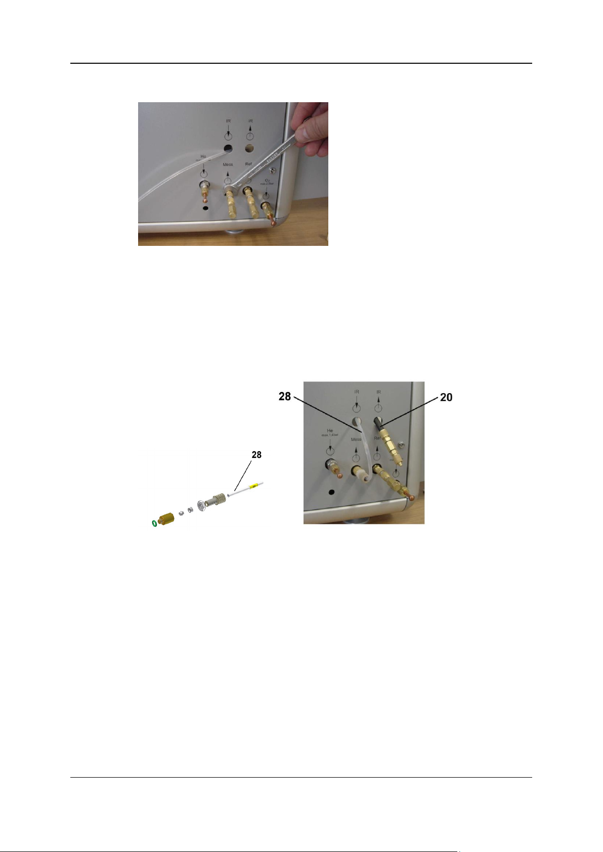
6 - Sulfur determination with combined NDIR for measuring CO and SO2 95
Remove the connecting piece of the measure gas outlet using a 7mm open jawed wrench.
Lead tube no. 25 (28) from inside to outside through the hole (IR inlet) and connect it to the
measure gas outlet using a knurled reducing nipple.
Lead the outlet hose line of the NDIR photometer no. 29 (20) from inside to outside through the
hole (IR outlet).
The double nipple connector at the end of the hose line no. 29 (20) is used to connect the on-site
waste gas line.
CAUTION: Follow the notes about discharging the waste gases into the open or into a vent
in the vario EL cube main operating instructions!
Connect the opposite end of tube no. 25 (28) (red cap) as well as the inlet hose line no. 28 (19)
of the NDIR photometer to the U tube (29).
Close the left and right side door.
Installing the software
If necessray, you have to update the instrument software for operation with the IR photometer.
Proceed as follows:
Insert the provided CD "IR option" to the CD drive of the PC and start the software update.
The current software will be automatically installed on the PC.
Follow the instructions on the screen.
As the case may be, an update of the device firmware becomes necessary. During the re-start it
will be recognized by the software and an update procedure will be performed automatically.
The installation of the NDIR photometer and the modification is completed.
Variants Operating Instructions vario EL cube ©Elementar Analysensysteme GmbH

6 - Sulfur determination with combined NDIR for measuring CO and SO2 96
Variants Operating Instructions vario EL cube ©Elementar Analysensysteme GmbH

Target group
In this chapter
Analytical characteristics and technical specifications ...................................................................98
Substance digestion and functional diagram .................................................................................98
Detection .....................................................................................................................................100
Tube fillings .................................................................................................................................100
Notes on performing calibration ...................................................................................................102
Chlorine analyses in routine operation ........................................................................................103
Notes on sensitivity and measuring range ................................ ................................ ...................104
Cross-sensitivity of the EC cells ..................................................................................................105
Quantitative conversion from Cl to HCl ........................................................................................106
Maintenance of the HCl EC cells .................................................................................................106
Leak test ................................ ................................ ......................................................................107
Modification to Cl operation .........................................................................................................108
C H A P T E R 7
Chlorine determination with EC cell
Personnel involved with the instrument.
Purpose
This section describes the special features of the chlorine determination with EC cell.
Variants Operating Instructions vario EL cube ©Elementar Analysensysteme GmbH

7 - Chlorine determination with EC cell 98
Analytical characteristics and technical specifications
Analytical characteristic
Comments
Analysis method
Chlorine determination by combustion, HCl detection with EC cell.
Detector
EC cell
Sample weight/sample volume
Approx. <1 to 30 mg (corresp. 1 to 30 µl) depending on the
substance. For soil samples the weight can be increased up to 100
mg if required.
Working range
(depending on kit and measuring
mode)
15 - 70 µg Cl (EC cell 0 - 200 ppm HCl).
Precision / standard deviation
<5% rel., for homogeneous standards
Duration of analysis
(depending on element content
and sample weight)
approx. 7-10 min
Calibration
Linear and non-linear curve adjustment; total work range.
Data storage and data output
Storage on hard disk or external storage media.
LIMS transfer possible.
Data output to screen and printer.
Reference value
Technical specifications
Supply gases
Synthetic air.
Consumption of supply gases
Per analysis approx. 3.5 litres synthetic air. Due to the high gas
consumption, the use of an economic air generator is
recommended.
Phase
Process
1
The substance to be analyzed is digested in oxidative atmosphere at a temperature of
approx. 1,150 °C by means of combustion.
2
For the digestion weigh in the sample into tin boats (for liquid samples tin capsules are
available). The folded boat is thrown into the vertical quartz glass combustion tube by
means of an autosampler.
Analytical characteristics
The following table explains the analytical characteristics:
Technical specifications
The following table contains the technical specifications of the gas supply:
Substance digestion and functional diagram
Introduction
The following section explains:
Which process occur in the reaction tubes of the furnace.
How the reaction gas mixture is prepared for adsorption and separation into its constituents.
Processes during substance digestion and preparation of the reaction gas mixture
Substance digestion and preparation of the reaction gas mixture is divided into the following phases:
Variants Operating Instructions vario EL cube ©Elementar Analysensysteme GmbH

7 - Chlorine determination with EC cell 99
3
The chlorine in the sample is quantitatively converted to HCl with hydrogen in the sample
and, if necessary, with hydrogen in an additive.
4
Humidity / water is absorbed by a chemical drying substance (H2SO4 on carrier) which is
downstream the combustion tube.
5
HCl and neutral combustion products (N2, CO2, etc.) are subsequently transported to the EC
cell. The EC cell specifically reacts to HCl, thus, a gas separation is not necessary.
Notes
For a better understanding see also the following illustration (tubing diagram, chlorine determination).
Variants Operating Instructions vario EL cube ©Elementar Analysensysteme GmbH

7 - Chlorine determination with EC cell 100
Symbols
Two-way valve
Pressure sensor
Gas separation
Three-way valve
Loop
Measuring cell
Check valve
Heated tube
Sensor
Throttle
Drying
Hose line
Flow controller
Combustion
Copper tube
Flow sensor
Post combustion
Reduction
Pressure contoller
Actuator
The following list names the functional and basic symbols:
Detection
Introduction
The HCl detection is done by means of an EC cell. The data of the EC cell are as follows:
0 - 200 ppm HCl, corresponds 15 to 70 µg Cl. For measurements of chlorine concentrations in
the range of approx. 50 ppm up to approx. 4 %.
Note
The EC cell is slightly cross-sensitive to water vapor. Therefore, the measuring gas has to be dried.
A dyring tube will be installed behind the combustion tube.
Tube fillings
Requirements:
Before starting work, the following requirements must be met:
All quartz and glass components must be cleaned before their usage. Clean the tubes from
fingerprints by means of a suitable solvent (e.g. acetone) before installing. Otherwise there is a
risk of crystallization which will lead to premature ageing of the quartz.
Use chemicals necessary for the tube fillings only in the appropriate quality. Delivery directly from
the instrument manufacturer.
Safety instruction
Strictly observe the safety instruction "Filling reaction tubes" under Warning notes during
operation (on page 11).
Filling of the quartz combustion tube for Cl determination
The arrangement of the filling must be carried out as shown in the following illustration.
Variants Operating Instructions vario EL cube ©Elementar Analysensysteme GmbH
 Loading...