

Page 1
PLEASE LEAVE THESE INSTRUCTIONS BEHIND WITH THE DEVICE
Element4 Modore 75H
INSTALLATION & USER MANUAL
WARNING - THE COMBUSTION CHAMBER OF THIS STOVE SHOULD ONLY BE OPENED AND SERVICED BY A REGISTERED GAS INSTALLER
Page 2

INSTALLATION MANUAL
2
Page 3

INSTALLATION MANUAL
3
THIS PRODUCT IS NOT SUITED FOR USE AS A PRIMAIRY HEAT SOURCE.
Page 4

4
INSTALLATION MANUAL
Page 5

5
INSTALLATION MANUAL
CONTENTS
1 CE statement 6
2 Important safety information 6
3 Warranty 7
4 Remote control with full electronic ignition 8
4.1 Adjusting the communication code 8
4.2 Igniting the pilot light 8
4.3 Igniting the main burner 8
4.4 Switching off the replace 8
5 Installation preparation and - instruction 9
5.1 Relevant norms and guidelines 9
5.2 Attention points gas replace 9
5.3 Attention points gas connection 9
5.5 Requirements ue and wall terminals 9
5.6 The chimney 9
6 Fire safe installation 10
7 Attention points gas ue 12
7.1 Installation of ue material 12
7.2 Calculate chimney 12
8 Installation check and rst usage 12
8.1 Renovation/new construction 12
9 Elektrical circuit 13
9.1 Domotica 13
9.2 Element4 ProControl App. 13
10 Maintenance instruction 14
10.1 Maintenance in the combustion chamber 14
10.2 Cleaning the glass 14
11 Decoration arrangement 16
12 User Instruction 17
12.1 Hand over to the customer 17
12.2 Maintenance instructions for the installer 17
12.3 Anti-reective glass 17
12.4 Ceramic parts 17
12.5 Replacement of parts 17
12.6 Packaging materials 17
13 Warranty conditions 18
A First aid for malfunction 20
B Errors codes Procontrol App 24
C Faults and error codes in the remote 26
C.1 Router information 26
C.2 Wi-Fi Router 26
C.3 Jammers 26
C.4 2.4 or 5 GHz band? 26
D Location terminal 27
E General rules for ue gas extraction 28
E.1 Power-Fan 28
E-2 Determining the ue gas extraction diameter: 28
F Calculation table ue gas limiter 29
G Technical data 30
H Ecodesign 31
H.1 Ecolabels 31
I Dimensional drawings 32
Page 6

INSTALLATION MANUAL
6
2 Important safety information
The fireplace may only be installed by a qualified installer/dealer,
following these installation instructions. We advise you to read
these instructions properly, before commencing the installation
of your device.
Before installation check the decive for transport damage and
inform your supplier immediatly if damage is found.
Check the data on the dataplaat. The gas type and pressure
should check out with those locally available. The data plate is
mounted to the device. Make sure it is accessible at all times.
This device is design to be used with natural gas or LPG. The
device can only be used with the type of gas specified on the
data plate at the time of purchase.
The device may never be used without the glass of when glass
is broken. The flue gasses can get into the installation room. The
settings and construction of the device must not be changed!
Parts are only to be changed with original parts by the original
manufacturer.
The device is provided with a special set of decorative materials.
Do not place any extra imitation logs or decoration material on
the burner or in the combustion chamber. See chapter 11 for an
instruction on how to arrange the decoration properly.
The glass and frame on this appliance acts as a fireguard
conforming to BS: 1945 – 1971 and satisfies the Heating Appliance
(Fireguards) regulations 1991. No part of the window or frame
should be permanently removed. It does not give protection for
young children aged or infirm, extra guarding (conforming to
BS8423: 2002) should be considered so the special hazards that
exist in nurseries and other places where there are young
children, aged or infirm persons are minimized.
The heat that is coming from the device may eect the materials
in its surroundings. Always take into account to correct safety
distances. For more information see chapter 6.
1 CE statement
We hereby declare that the design and construction of the
Element4 gas appliances are complying to the essential
demands and regulations for gas products.
Product:
• Gas fireplace, local spaceheater
Model:
E4-18
• Modore 75H
Applicable EG-guidelines: (EU) 2016/426 (GAR)
Applicable harmonized norms:
• NEN-EN-613
• NEN-EN-613/A1
This declaration loses its validity when changes to the device are
made without the written permission by Element4. You can ask
for a copy of the test certificates of all models via our general
e-mail adress, which is found on the back of this manual.
J. Kempers
CEO
Page 7

INSTALLATION MANUAL
7
For a service provision to house, outside the warranty period,
the following costs ar ebeing charged:
• Materialcosts
• Working hourse
• Call-out costs
The warranty is not appicable in the following cases:
1. When one of the previous point is not met
2. When changes are made, of which Element4 is not made
aware of / has approved of upfront
3. When device is not installed and/or used properly according
to the installation manual.
4. When other then the prescribed decoration material is used.
5. When the device is installed (partially or fully) with other
materials than prescribed in this manual.
3 Warranty
NB: Should a problem occur, that you are not able to fix yourself
with the help o the support in Appendices A to C, please contact
you installer or dealer.
The Element4 devices on which this warranty is applicable are
made of high quality materials. Should any problem or defects
still occur the following provision are in eect;
1. Before any installation, the installer will ensure himself of
the good quality and operation of the flue channel. The
gas fireplaces are to be installed by a competent installer,
according to the rules and regulations that are applicable
in the country (or even region) of installation and those as
described in this manual.
2. There is a warranty period of two years for all Element4
devices, starting from the moment of purchase. The date
of purchase should be mentioned clearly on the purchase
invoice.
3. The ceramic glass is not included in the warranty, as are the
physical or chemical outside influences during transport,
storage or montage.
4. If a malfunction should occur during warranty period that
is a consequence of a assembly error or material defect,
Element4 will provide a free replacement part to the installer,
without compensation for disassembly or montage.
5. In case the installer is not able to fix the problem himself, a
request can be made to Element4 to do it for him, as long as
the service can be done within the borders of the Benelux.
6. Only aer consulation up front, the device or loose parts
can be send for check up or replacement. These goods are
the be send with the necessary warranty documents and
the date of purchase.
7. When a house visit should occur for service purposes
by Element4 (within the borders of the Benelux) during
warranty period, the right documentation (i.e this page and
a proof of purchase) should be available.
Page 8
8
INSTALLATION MANUAL
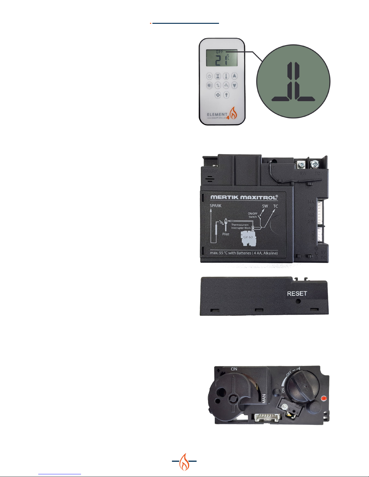
Figure 4-3: Main burner ignition
Figure 4-2: Receiver (top - and side view)
Figure 4-1: Remote and ignition sign
4 Remote control with full electronic ignition
The unit is operated using a remote control (fig. 4-1). The ignition,
regulating the flame height and switching o is done using the
remote control, operating a receiver (fig. 4-2) in the control box.
The receiver and the remote control is powered by batteries.
4 pen lite (type AA) batteries are required for the receiver; 2
penlight batteries (type AAA) for the remote control. The life of
the batteries is about a year with normal use.
4.1 Adjusting the communication code
Before using the appliance, a communication code must be set
between the remote control and the receiver. The code is chosen
at random from the 65000 available codes. Therefore there is a
slim chance that other remotes in your area use the same code.
You must work as follows
Press the reset button on the receiver until you hear two beeps.
Aer the second longer signal, let go of the reset button. Fig. 4-2
Within 20 seconds, press the down arrow on the remote control
until you hear a sound signal. This is confirmation of the proper
communication.
4.2 Igniting the pilot light
Check that the control knob (A) is in the ON position. Fig 4-3. Press
the button on/o button of your remote control and continue to
hold down (3 to 5 sec.) until you hear two short beepes.
The ignition sign will appear at the top of the screen (fig. 4-1)
Now release the button. The ignitionprocedure is started.
NB: If the pilot light doesn’t remain lit aer 3 attempts you must
turn o the gas tap and warn your installer.
4.3 Igniting the main burner
Aer starting the pilot, knob B will automatically rotate counter
clockwise and the main burner will start burning. Fig 4-3. Always
wait 5 minutes aer killing the pilot light before you start the
pilot flame again.
NB: The pilot light must ignite the main burner, evenly and
without a thud, if it does thud, close the gas tap and warn your
installer.
4.4 Switching off the replace
You switch o the fireplace by pressing the on/o button, this
also turns o the pilot light! For a detailed description of the
E-save remote control, please refer to the E-save manual which
is included with the fireplace.
A B
Page 9
9
INSTALLATION MANUAL
5 Installation preparation and - instruction
The device is developed, tested and approved conform the
applicable standards for the usage, the performance and safety
of the product. The installation of your device must apply to
the current building prescriptions. We advise to make use of
a qualified gas installer for the installation of your device. The
installer can provide you with all information regarding the
safety regulations of the installation.
5.1 Relevant norms and guidelines
The installation must be carried out in accordance with the
following regulations:
• Department of the Environment, the Building Standards
(Scotland) (Consolidation) Regulations issued by the
Scottish Development Department.
• BS 5440 part 1
• BS 5871 part 2
• BS 6891.
In the Republic of Ireland the installation must also conform to
the relevant standards, particularly in regard to flue sizing and
ventilation. Refer to documents;
• IS813
• ICP3
• IS327
• Any other rules in force.
This appliance must be installed in accordance with the rules
in force and used only in a suiciently ventilated space, and is
intended for use on a gas installation with a governed meter.
5.2 Attention points gas replace
This device can be place in a new or existing situation. The device
can be installed in a fully enclosed or mechanically ventilated
room without extra ventilation.
Before installation of these appliances, the area into which the
fire is to be fitted must be cleared of all debris (including dust), in
particular combustible material.
5.3 Attention points gas connection
The gas connection should apply to the local norms in force.
Calculate the diamater of the gas flue, such that no pressure loss
is occuring in the pipes. Place a shut-o valve in the near vicinity
of the device. Position the gas connection, such that it is always
accessible for service purposes.
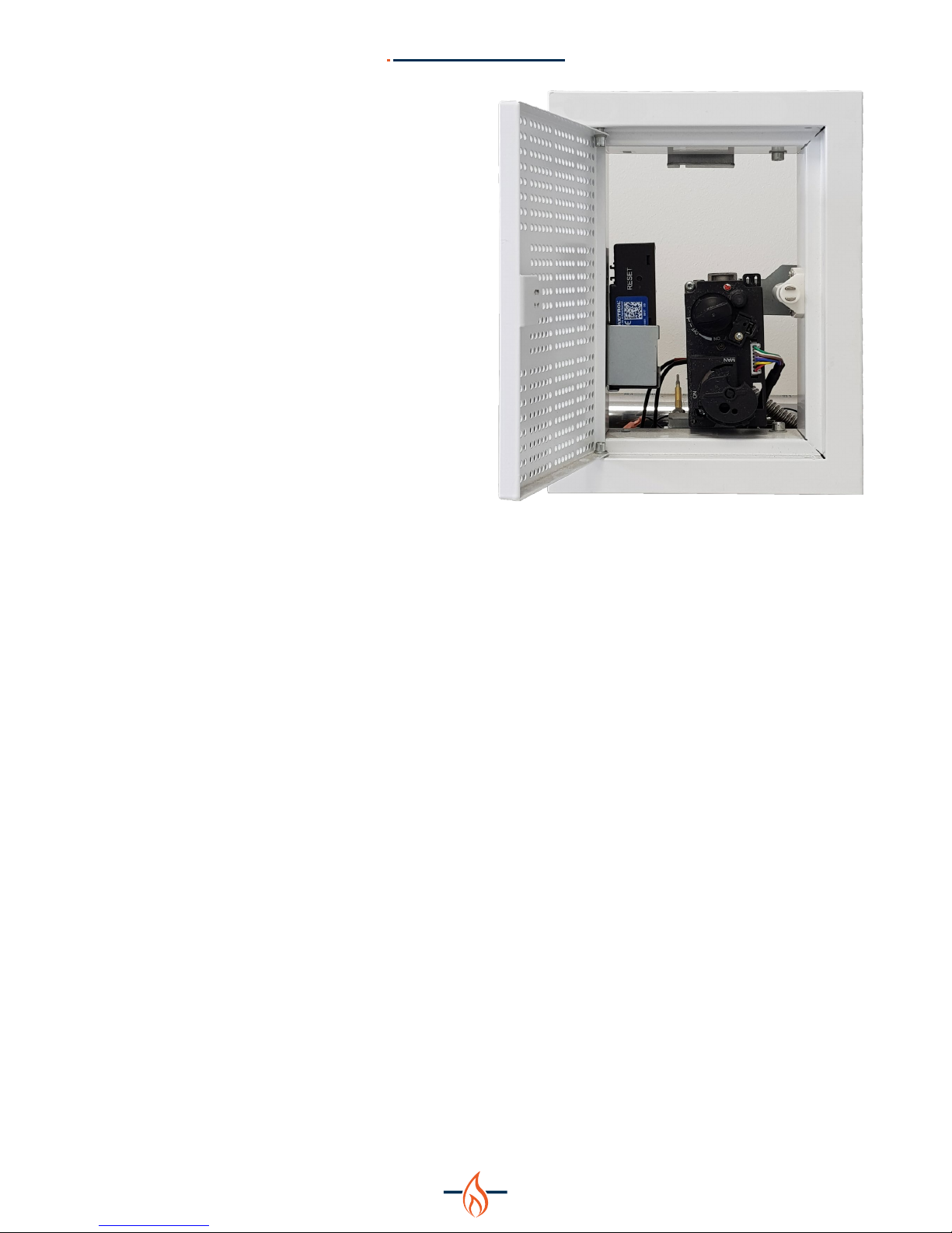
Put the gas block and receiver behind the included service hatch.
Make sure that it is always accessible for service purposes. (See
Figure 5-1)
5.5 Requirements ue and wall terminals
The European CE-marking for the device is only applicable to
the flue materials specified by the supplier. The device must be
installed with the stainless steel flue material US by Metaloterm/
On top. The usage of other concentric stainless steel material is
only permitted when it has the same technical specification as
the previous mentioned systems.
Only when these materials are used a good and safe performance
can be promised by Element4.
The flue channel can work both a wall terminal (C11) as a roof
terminal (C31), as well as flex pipes in an existing channel.
Please check, whether the desired terminal complies with the
regulation for your situation (See: appendix D).
It is possible that an extra shield is necessary when the terminal
is within two meters from the ground.
5.6 The chimney
Before the chimney is installed, we advice an operation test
with the device. The chimney should be constructed from noncombustible materials and cannot rest on the mounting frame.
Always use a chimney iron, when using bricks or cell concrete.
The chimney ventilation should meet the the local norms. A well
ventilated chimney makes sure the temperature is regulated to
ensure a proper operation of the electronics and the gasblock.
Furthermore, good ventilation helps to keep the convection air
under 85oC. Use the ventilation grate (CVRE4) and service hatch
(BDLE4) by Element4. See the measurements in appendix I.
More on chimney construction in the next chapter.
Figure 5-1: Service hatch
Page 10
10
INSTALLATION MANUAL
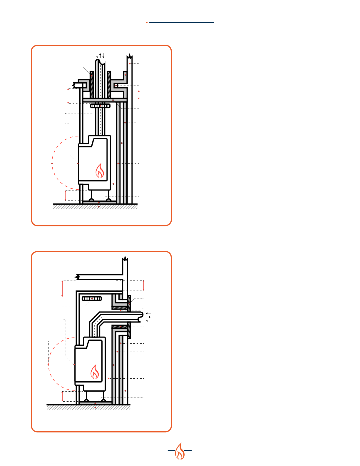
Air cavity 50mm
Nonflammable
cover
Wall insulation
Distance to
insulation
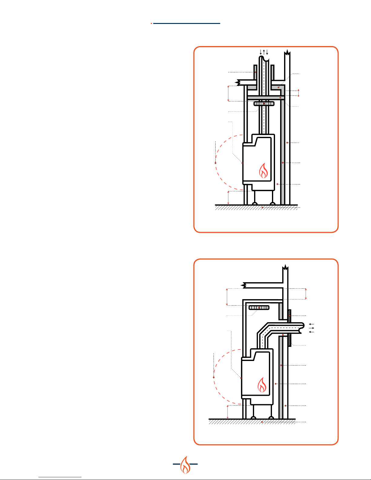
Figure 1B: Non-flammable wall-/ceiling
Construction for a situation with
a non-flammable wall (U-Value ≥ 0,4Wm
2
/K)
Distance ≥ 100mm
Non-flammable
wall
Non-flammable
floor
Convection grille
2x 150cm
2
Distance to
convection grille
≥ 200mm
Radiation distance
to flammable
objects ≥ 500mm
Outside gas
fireplace ~200ºC
Distance fireplace to
non-flammable
floor ≥ 100mm
Figure 6-2: Flammable wall-/ceiling
Figure 1A: Non-flammable wall-/ceiling
Construction for a situation with
a non-flammable wall (U-Value ≥ 0,4Wm
2
/K)
False ceiling
Covering of
non-flammable
material
Convection grille
2x 150cm
2
Distance to
convection grille
≥ 200mm
Distance ≥ 100mm
Insulation
ceiling connection
Non-flammable wall
Radiation distance
to flammable
objects ≥ 500mm
Wall insulation
Distance to
insulation ≥ 20mm
Non-flammable floor
Outside gas
fireplace ~200ºC
Distance fireplace to
non-flammable
floor ≥ 100mm
Figure 6-1: Non-flammable wall-/ceiling
6 Fire safe installation
To install a gas fireplace as safely as possible, several installation
preparations need to be made. This overview can be used to
assure the fire safety of a conversion of a fireplace.
Fire safety device set-up
Install the device such that there are no flammable materials
around the device or chimney. The device must never be placed
against a back wall of flammable materials.
Flammable materials, such as wood, can combust at a
temperature of 85°C. At high temperatures this can happen
within several minutes (over 200°C) or at lower temperatures
(more than 85°C) this may occur over a period of weeks.
A gas fireplace can achieve temperatures of over 200°C.
Therefore one should use only non-flammable materials around
the fireplace and in the cove.
It is important to follow the installation regulations below
carefully. When the regulations are insuiciently- or not provided
with the aspects of fire safety, the instructions according to NPR
3378-20:2010 are leading.
Protection of wall and ceiling
There are two kinds of walls/ceilings that can be distinguished,
respectively;
1. Walls/ceilings that are made of – or contain flammable
building materials, and all walls on which flammable objects
(e.g. built-in furniture or wooden panels) are mounted on
the side of the wall that is turned away from the fireplace.
2. Walls/ceilings made of mineral building materials (gas
concrete, bricks, lime sandstone etcetera.) of more than
10cm thickness.
Assembly regulations
(Figure 6-1 and 6-2)
• Cover the walls/ceilings with a non-flammable, fire resistant
plate, according to EN 13501-1:A2
• Place a non-flammable, fire resistant plate in front of the
first one at a distance of 2cm.
• Make sure that the two plates are not attached to each other
by screws or nails. Due to their conductivity these metals
can cause problems.
Page 11
11
INSTALLATION MANUAL
Cover of
non-flammable
material
Air cavity 20mm
Air cavity 50mm
Distance
≥ 100mm
Non-flammable
cover
Wall insulation
Distance to
insulation
≥ 20mm
Non-flammable
insulation plate
Figure 2B: Flammable wall-/ceiling
Construction for a situation with
a flammable wall (U-Value ≥ 0,4Wm
2
/K)
Flammable wall
Non-flammable
floor
Flammable floor
Convection grille
2x 150cm
2
Distance to
convection grille
≥ 200mm
Radiation distance
to flammable
objects ≥ 500mm
Outside gas
fireplace ~200ºC
Distance fireplace to
non-flammable
floor ≥ 100mm
Figure 6-4: Flammable wall-/ceiling
Air cavity 50mm
Air cavity 20mm
Non-flammable
insulation 25mm
Distance to
insulation ≥ 20mm
Figure 2A: Flammable wall-/ceiling
Construction for a situation with
2
False ceiling
Distance ≥ 100mm
Flammable wall
Wall insulation
Insulation plate
Nonflammable
floor
Flammable floor
Covering of
non-flammable
material
Convection grille
2x 150cm
2
Distance to
convection grille
≥ 200mm
Radiation distance
to flammable
objects ≥ 500mm
Outside gas
fireplace ~200ºC
Distance fireplace to
nonflammable
floor ≥ 100mm
Figure 6-3: Non-flammable wall-/ceiling
Assembly regulations
(Figure 6-3 and 6-4)
• Load-bearing walls and ceilings must be covered in a
protective fire resistant plate.
Never use flammable materials around the fireplace or cove.
The minimal distance between the device and non-flammable
materials must be at 50 mm to ensure a convection air flow.
Make sure there is a good air ventilation in the cove. The
temperature that leaves through the ventilation grilles must not
be higher than 85°C. Therefore one should always make sure
there are enough ventilation grilles in the upper and lower parts
of the cove.
Hot air outlets and ventilation grilles
The ventilation grilles are to be placed at a minimal distance of
20cm from the ceiling and 30cm from any built-in furniture from
the side, any flammable material or load-bearing concrete parts.
To avoid heat accumulation in the cove a non-flammable false
ceiling is to be placed directly above the grilles. The ventilation
grilles need to be easy to clean at all times.
Floor protection
Between the device and the ground a minimal distance of
10cm is to be taken into account. The temperature of the floor
under the device needs be less than 85°C and the floor of the
conversion around the fireplace is to be constructed of nonflammable materials. If necessary the floor is to be covered with
an insulation layer to protect it from unauthorized temperatures.
Radiation
When the fireplace is turned on, heat radiation will escape
through the ceramic glass and will heat up the environment.
Therefore it is important that a minimal distance between
the ceramic glass and any flammable material in front of the
fireplace is 40cm.
Electrical pipes
The conversion has to be free of the usual electric installation
pipes, if these are not protected against temperatures over
30°C by the necessary precautions. Special pipelines with an
heightened heat resistance are permitted.
Page 12
12
INSTALLATION MANUAL
8 Installation check and rst usage
8.1 Renovation/new construction
When firing up the device for the first time, make sure the device
burns for several hours on the highest level, to ensure the lacker
to harden. Make sure the device is ventilated enough so the
possible released fumes are being abducted. We advice to be as
little in the room as possible during this process.
Because a fireplace is a heat source, natural convection will
occur around it. Solid particles in the circulating air may burn
and settle down on cold surfaces, causing discoloration.
Discoloration is an annoying problem and it is diicult to solve.
These particles can come from construction moisture or
cigarette smoke, but also they might be volatile components in
paint, construction materials or carpeting. For newly constructed
chimneys or aer a big reconstruction, it is advised to wait a
minimum of six weeks before firing a fireplace.
8.2 Checking the gas lines
To be able to check on the gas lines, it is necessary to have the
right equipment. If necessary take out the glass of the device
and use the measuring point (see figure 8-1), to check the supply
pressure on the gas pipes.
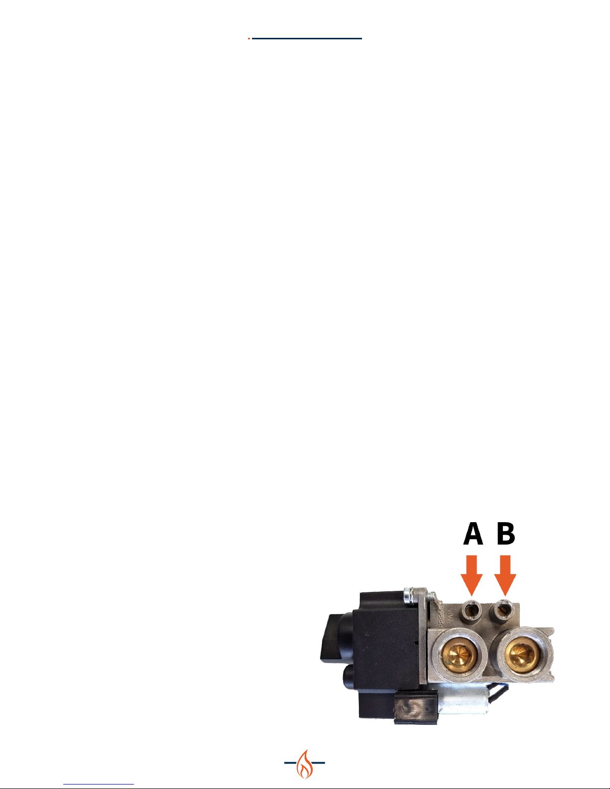
A= Supply pressure
B= Burner pressure
Make sure the cables of the ignition are hanging loosely under
the device, to ensure a good ignition. Remove any tie wraps or
other cable binders.
Check the pilot and second thermocouple for obstructions and
check the air tightness of the system. Technical specifications
can be found in Appendix G.
Figure 8-1: measure points on the gas block
7 Attention points gas ue
To guarantee the fire safety regarding you flue gas configuration
a casing is necessary. For this case non-combustible materials
should be used. Make sure to ventilate a sha and never to
insulate it, to make sure the hot air is able to get away.
Every transit or terminal should be made such, that the warmthinsulation and non-combustability is guaranteed, according to
the building regulation.
7.1 Installation of ue material
Follow the following instrucions for the installation of flue
materials;
• Drill a hole of 160 mm for the wall or roof transit with a 150
mm diameter flue connection, and 210 mm with a flue with
a diameter of 200 m.
• Keep a distance of at least 50 mm between the outside of
the concentric pipes and the wall or ceiling.
• Provide a (fire) safe transit construction in wall, floor or roof
sheeting
• Build the system from the fireplace.
• Assemble pipes in the correct direction! The inner pipe goes
into and the outer pipe goes over the fireplace connection.
• Make sure the tubes are suiciently braced, so the weight of
the tubes are not supported on the hearth.
• The concentric pipes could come loose due to expansion
and cooling down. It is recommended that a chuck parker
be used in places that are inaccessible aer installation.
• The horizontal drain portion must be fitted sloping to the
hearth.
7.1.1 Adapting the length of the chimney
Not all parts can be adjusted! To fit the drainage system
correctly, you are to use an adjustable fitting. You can use an
adjustable concentric pipe, wall or roof fitting. To get a sealed
flue gasconnection, the inner pipe must always be 2 cm longer
than the outer pipe. Always attach adjustable parts with a chuck.
7.2 Calculate chimney
For proper operation of the fireplace it is important that the flue
pipe meets the requirements. Do determine this, we prepared a
calculation chart. (See Appendix E & F)
Page 13
13
INSTALLATION MANUAL
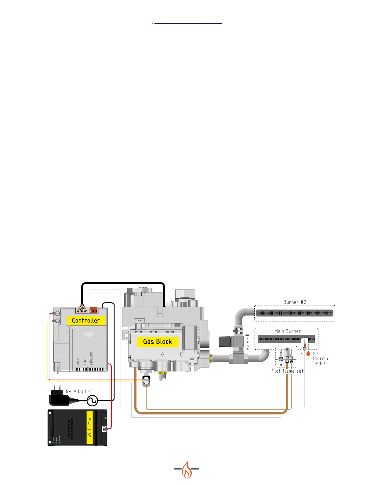
9 Elektrical circuit
Figure 9-1 shows a simplified connection circuit for the (Bi)
Optica. The standard device is provided with a set of batteries,
althought it is possible to put the receiver on the electricity net
via adapter. Should one choose any add-ons for their device
such as a wi-fi module, the adapter is mandatory to ensure
proper functioning of the fireplace.
9.1 Domotica
The receiver oers the possibility to be connected to a domotica
system. A special connector is being supplied for this. Type: G60ZCE
9.2 Element4 ProControl App.
It is possible to operate your device via smartphone or tablet
with the ProControl App, available in the appstore on iOS and
google play on Android.
The app has a user friendly, interactive layout and the design is
adjusted for Element4 devices. Up to eight devices can be used
with one app, in the situation that multiple fire are installed in
the same location.
Another functionality of the app is to pre-set the temperature
of you device, for a period of one week, to ensure yourself of an
optimal desired room temperature. Also the device can changed
between high and low flames and it features an eco-setting.
The amount of users, that can operate the device is unlimited,
so every family member can make use of it, by easily making a
personal account. By two-way communication, one can check
on the device at any moment.
To use the app, the device needs to be provided with the correct
receiver and remote combination and also the receiver should
be connected to net electricity with a 220V adapter, which will
replace the batteries.
Necessities for the installation of the ProControl:
• 220 volt electricty near the fire
• Wi-Fi code of the router
• Smart Phone or tablet
• ProControl manual
Should any problems occur you can always check appendix B.
Figure 9-1: Electronic circuit Modore 75H
Controller
Gas Block
RELAIS
AUX
MODULE
Main Burner
Pilot flame set
2
nd
thermo-
couple
6V Adapter
Wi-Fi Mod
Valve #1
Burner #2
Page 14
14
INSTALLATION MANUAL
10 Maintenance instruction
This part of the manual focuses on maintenance. To ensure the
optimal flame picture of your device, an annual maintenance by
a competent company or installer is prescribed.
10.1 Maintenance in the combustion chamber
During maintenance the glass windows of the fire need to be
removed. To do this follow the following steps:
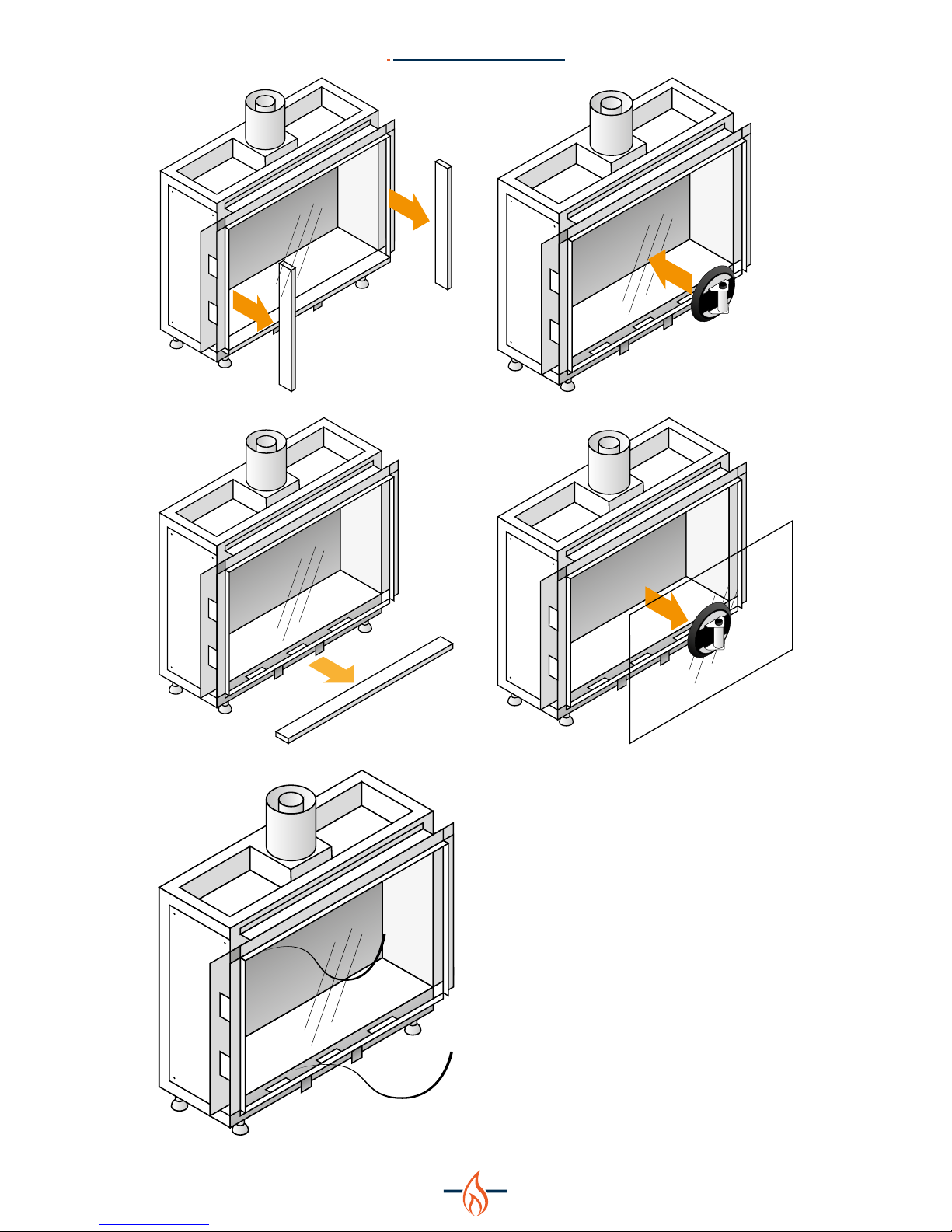
10.1.1 (Dis)assembly of the trims
For a tight finish of the fireplace, trims are available. During
maintenance these trims must be removed, before the glass
can be removed. Please follow these steps:
Disassemble:
• Remove both the side trims. They are held by magnet
snappers, Figure 10-2
• Remove the under trim aerwards (figure 10-3).
Assembly:
Put the trims back in reversed order.
10.1.2 Remove glass
To be able to cleam the glass on the inside, one needs to
remove the glass. To do this follow these steps:
• Check, whether the trims are removed in as in step 10.1.1 .
• Remove the cords that hold the glass. (See Figure 10-4)
• Put the section cup on the glass and make sure it is properly
vaccuumed, so it will not come o (fig 10-5).
• Li the glass for a little bit and tilt it out through the opening
(See figure 10-6).
NB: Put away the glass in a safe place, when you are not using
it, to make sure it will not damage during maintenance. Remove
the suction cup aer putting away the glass to avoid tracing or
stains.
For the Bioptica, to take out the other side of the glass, all steps
are repeated at the other side of the fireplace.
10.2 Cleaning the glass
Keep in mind the following when cleaning glass:
• Always clean the glass at room temperature.
• Use cleaning supplies qualified by Element4.
• When you clean your Anti-Reflective glass, make sure
you use this with the special Element4 cleaner, which is
available only via Element4.
• Use only a microfibre cloth. Other materials such as kitchen
towels, steel wool etcetera can cause scratches or damage
the coating on the glass.
• Should there occur stains on the glass, remove them
regulary, for the can burn the glass.
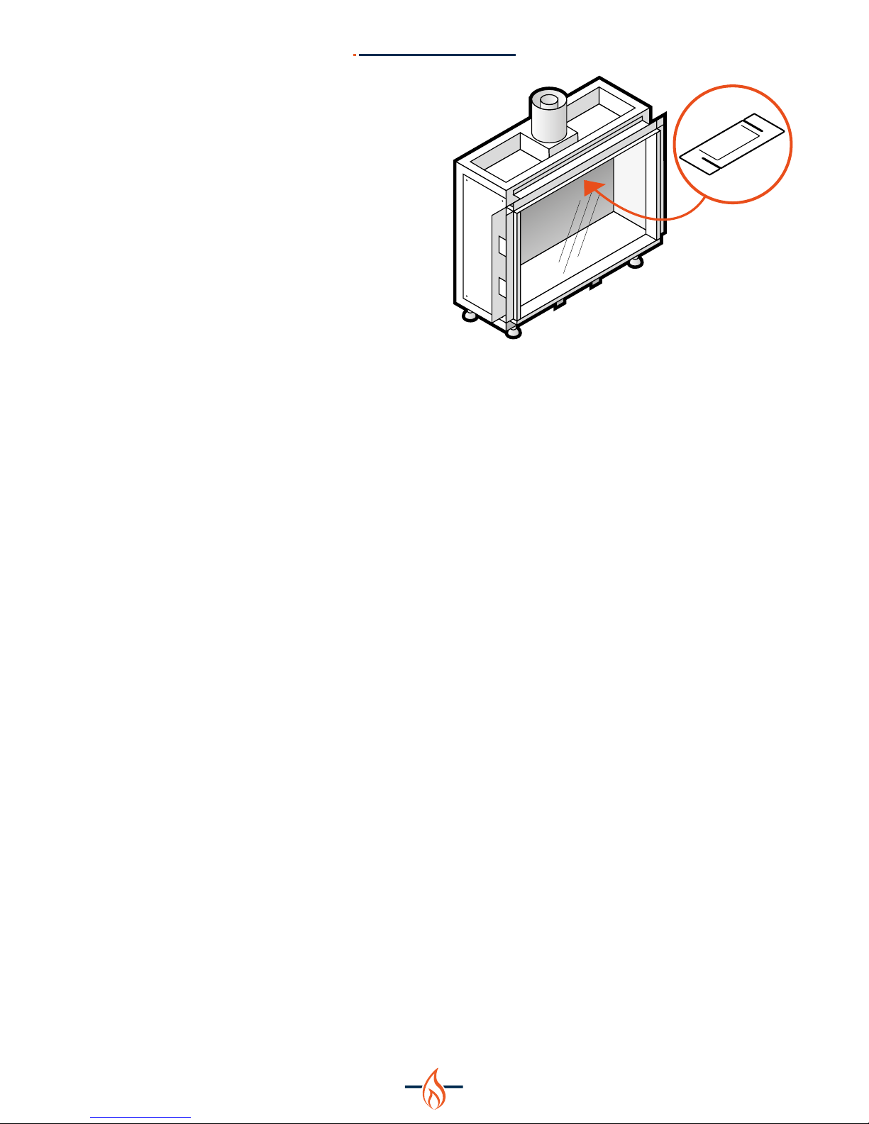
Afbeelding 10-1: Modore 75H
Page 15
15
INSTALLATION MANUAL
Afbeelding 10-6: Removing glass
Afbeelding 10-5: Put on the suction cups
Afbeelding 10-4: Removing cords
Afbeelding 10-3: Removing lower trim
Afbeelding 10-2: Removing side trims
Page 16
16
INSTALLATION MANUAL
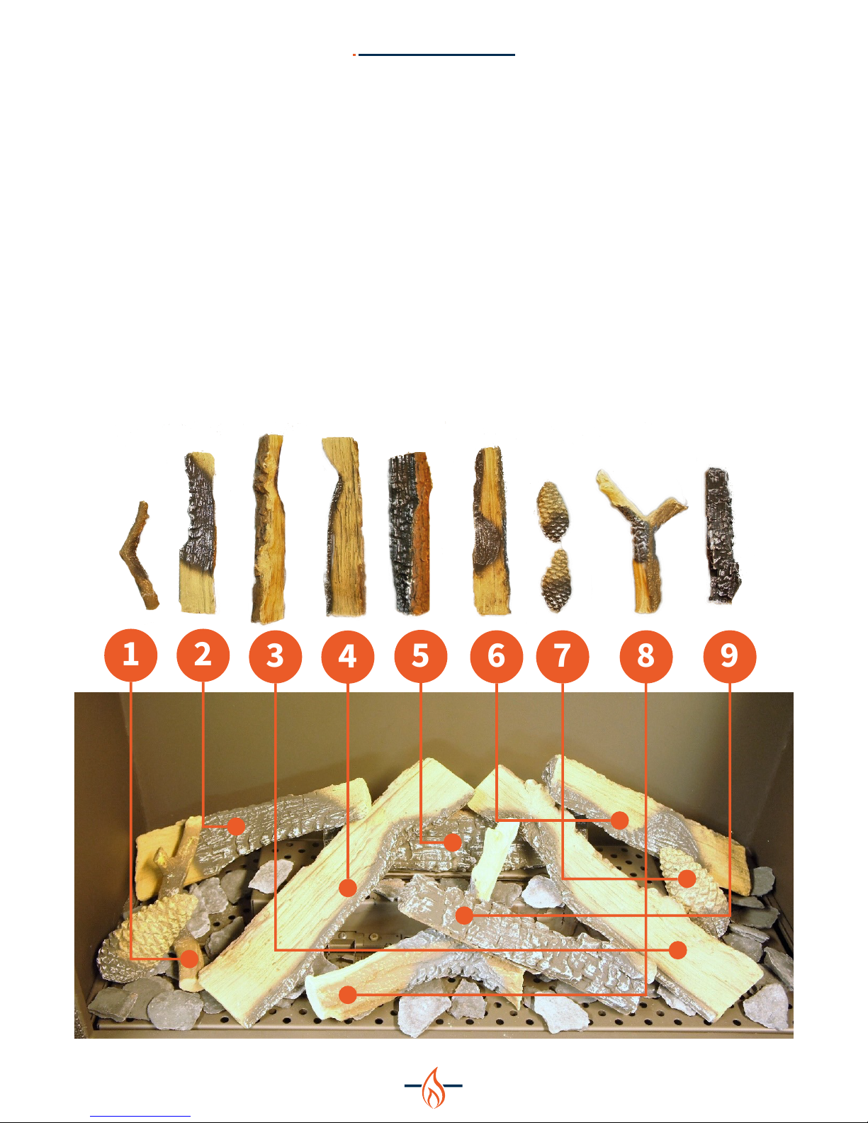
11 Decoration arrangement
Only the ceramics supplied with this appliance are to be
used. The ceramics must be laid only as shown on this page.
Replacement parts are available from your dealer, but should
only be installed by a qualified installation engineer.
Ensure that the grate is sitting firmly in the base of the fire
box, with the long slot in the centre of the Grate aligning with
the centre slots on the Burner. The Pilot flame must be visible
through the grate and the cut-out in the Pilot Shield.
Ensure that a number of holes in the Grate and the Pilot area are
free of embers. Aer placing the embers and logs accordingly
sprinkle some ashes over the logs and embers.
Finally check the pilot is clear, no embers have entered the Pilot
area and the cross lighting is good before the glass is replaced.
An elaborate instruction is available via Element4 or on the log
set instruction that are supplied with every device on purchase.
1 2
3
4
5
6 7 8 9
Afbeelding 11-1: Logset and arrangement for the Modore 75H
Page 17

17
INSTALLATION MANUAL
of hard (sanding) sponges, abrasives and cleaning agents with
ammonia is prohibited. Only use a neutral cleaning product
(neither acidic nor alkaline), such as Element4 window cleaner
(Item No. 4500926). The cleaning agents that you normally use
should therefore not be used with an anti-reflective glass. Use a
so cloth or sponge (not paper).
Just as with ordinary ceramic glass, the white haze that results
from the first combustion must be removed with anti-reflective
glass. Aer that, sporadic maintenance is suicient. Always
rub the window completely dry: Residual water can stain the
coating. Fingerprints are more visible on anti-reflective glass,
therefore wear (rubber) gloves when grasping the window. If the
window is lied with a suction cup, the rubber of the suction cup
must be dry to avoid damage to the coating.
12.4 Ceramic parts
This appliance is equipped with a ceramic fire bed with heatresistant ceramic fibers, or artificial glassy silicate fibers.
Excessive exposure to this material may cause irritation to the
eyes, skin and respiratory tract. We therefore recommend that
the dust emission is reduced as much as possible when handling
these materials
12.5 Replacement of parts
If parts need to be replaced, use only original parts from the
manufacturer. The warranty will be void if non-standard parts
are used. In addition, they can be dangerous.
12.6 Packaging materials
The packaging of the device is recyclable.
The following packaging materials may have been used:
• Cardboard
• CFC-free foam (so)
• Wood
• Plastic
• Paper
These materials must be disposed of in a responsible manner
and in accordance with government regulations.
Batteries are regarded as chemical waste. The batteries must
be disposed of in a responsible manner and in accordance
with government regulations. Remove the batteries first before
discarding the remote control.
The government can also provide information about the
responsible disposal of discarded appliances.
12 User Instruction
We recommend that you have the appliance inspected annually
by a recognized installer to ensure safe use and a long service life
guarantee
12.1 Hand over to the customer
• User manual
• Installation manual
• Instruction card decoration material
• Suction cups
• Remote control
12.2 Maintenance instructions for the installer
Below is an overview of the minimum maintenance that must
take place annually;
• Remove the glass plate and remove all ceramic parts.
• Remove any dirt on top of the burner with a vacuum cleaner
and brush.
• Inspect the burner.
• Perform an ignition check.
• Check that the pilot light ignites the main burner free and
unhindered by ceramic material.
• Perform a flame failure check
Maintenance on the burner should not be necessary. If this is
the case, check the set pressure at the inlet to the burner. The
correct pressure is stated in the back of this manual.
Wood arrangement
Brush the imitation logs and replace any broken or damaged
parts (see earlier in this manual).
Shingles or gray stone:
• Never place more than 1 layer over the burner
• Multiple layers will aect the fire image adversely
• Check the ceramic cord on the glass plate
• Reinstall the glass plate.
• Check the installation for gas leaks.
• Check whether the facade / roof outlet is free of obstacles.
12.3 Anti-reective glass
Anti-reflective glass for the gas fireplaces consists of polished
ceramic glass on which metal oxide coating layers have been
applied. The thickness of the coating is checked down to
the nanometer to perfectly control the reflection level. The
reflectance level of untreated glass is on average 8%, while an
anti-reflective glass provides a reflection of only 0.7%. Thanks to
the new coating technology, anti-reflective glass is completely
invisible when approached straight ahead. This gives the gas
fireplace a super realistic fireplace eect. In this way you use all
the advantages of a gas fire, while the atmosphere and warmth
nevertheless match the fireplace.
Maintenance of anti-reflective glass for anti-reflective windows
is of great importance to observe certain maintenance
instructions. In order not to damage the coating layers, the use
Page 18

18
INSTALLATION MANUAL
The following costs will be charged for services provided at
home outside of the guarantee period:
• Material costs
• Working hours
• Call-out costs
The warranty does not apply in the following cases:
• If the above points are not fulfilled or only partially.
• If, without the knowledge of Element4, any changes have
been made to the device.
• If the appliance was not installed in accordance with the
installation instructions, or was not used in accordance with
the operating instructions.
• If there are other than the required artificial wooden trunks,
ceramic material or stones on the burner bed.
13 Warranty conditions
Note: If there are faults that you can not solve yourself with the
aid of the fault solver in appendix 1, please contact your installer
or your dealer.
The Element4 products to which this warranty card applies
are carefully manufactured from high-quality materials.
Should errors or defects nevertheless occur, then the following
guarantee provisions apply:
1. Before proceeding with installation, the installer will first
ensure the good quality and proper operation of the flue
gas discharge duct. Gas appliances must always be installed
by a competent installer in accordance with national and,
if applicable, regional standards and according to the
installation instructions supplied with the appliance.
2. On the Element4 gas appliances, the warranty period is
2 years, starting from the date of purchase that must be
clearly stated on the purchase invoice.
3. The ceramic glass is not covered by the guarantee as well
as physical and chemical eects from the outside during
transport, storage or assembly.
4. If a fault should occur within the warranty period that is
the result of a manufacturing defect or material defect,
Element4 will send a spare part free of charge to the installer
to replace the defective part, without compensation for
assembly and disassembly.
5. If the installer himself can not rectify the malfunction,
he can request Element4 BV to do so, if this is within the
boundaries of the Benelux.
6. Only aer prior consultation can the entire device or parts
of it be sent for inspection or repair. These goods must
be accompanied by this completed warranty document
together with the dated proof of purchase.
7. In case of any on-home service by Element4 BV (only within
the Benelux) during the warranty period, the warranty
documents (this sheet together with the dated proof of
purchase) must always be submitted.
Page 19

19
INSTALLATION MANUAL
Page 20

20
APPENDICES
20
A First aid for malfunction
Below you will find an overview of the possible cause and
solution in the event of a failure.
Problem Possible Cause Solution
A No transmission
(motor will not
run)
1 Batteries in the receiver empty Replace the batteries (4x 1.5V AA)
2 Batteries hand remote empty Replace the batteries (2x 1.5V AAA)
3 6V-adapter defective Check the adapter
Replace the adapter if necessary
4 Hand transmitter not linked to the receiver Connect the hand transmitter to the receiver
Press and hold the reset button until you hear two beeps. Aer
the second longer tone, release the reset button. Press within
20 sec. on the down arrow on the hand transmitter
Two short beeps confirm that the code has been set.
Tip: For this action a video is available on our youtube
channel
B Receiver does not
receive a signal
1 Receiver defective Replace receiver
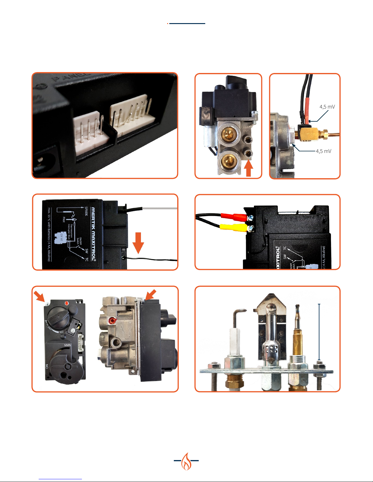
2 Bend pin connection on the receiver Bend the pen straight again (See Figure A-1)
3 Hand transmitter defective Replace the hand transmitter
4 No or bad reception. The receiver is in a metal
box! This disturbs the reception.
Change the position of the antenna (See Figure A-2)
C No ignition;
no beep
1 Receiver defective Reset the receiver (See K1)
If necessary, replace the receiver
D No ignition;
receiver gives a
five-second beep
1 Loose contact in the thermocouple circuit / wiring
2nd thermocouple
Check plug connections
Repair the wiring if necessary
2 Receiver defective Replace receiver
3 Magnetic coil defective Replace gas block / or only coil coil
4 Bent pin connection on the receiver See B2
5 Thermocouple broken
Check the thermocouple at the bottom of the pilot burner if
necessary. fracture.
Replace the thermocouple if necessary
E Ignition stops aer
1 spark
1 Mass on the gas block not OK • Remove the 20mm Torx screw (See Figure A-3)
• File or scrape the surface thoroughly
• Reinstall the Screw and tighten it securely
Tip: For this action a video is available on our youtube
channel
F No pilot flame but
there is an ignition
1 No gas Check / measure gas inlet pressure
2 Air in the gas line Venting the gas line can be done via test point A (See Figure A-4
Tip: For this action a video is available on our youtube
channel
3 Pilot flame blocked Check pilot burner
4 Thermocouple wiring is incorrect Check the wiring on the interrupter (See Fig. A-5)
Check the wiring on the receiver (See Fig. A-6)
Page 21
21
APPENDICES
40mm
Figure A-7: Pilot set
4,5 mV
4,5 mV
Figure A-5: interrupter
Figure A-1: Bend pin
Figure A-2: Antenna
Figure A-6: Wiring receiver
Figure A-3: Torx screw
Figure A-4: Testpoint A
Page 22

22
APPENDICES
Problem Possible Cause Solution
G The pilot light goes
on but goes out
immediately when
the main burner
switches on
1 Insuicient voltage across the thermocouple or
too much resistance in the thermocouple circuit
Place the measuring pins of the multimeter on the ground and
black cable of the breaker. This value must be at least 4.5 mV.
Tip: For this action a video is available on our youtube
channel
2 Gas pressure loss may cause the pilot flame to be
too small
Check and measure the pre-pressure via test point A (See
Figure A-4)
Tip1: Measure the pre-pressure load and unloaded
Tip 2: For this action a video is available on our youtube
channel
3 Thermocouple defect Replace thermocouple
Tip: Always use a new pressure piece when a thermocouple is
replaced
4 Thermocouple is incorrectly positioned Check the position of the second thermocouple. (See Figure
A-7)
H Check the position
of the second
thermocouple.
(See Figure A-7)
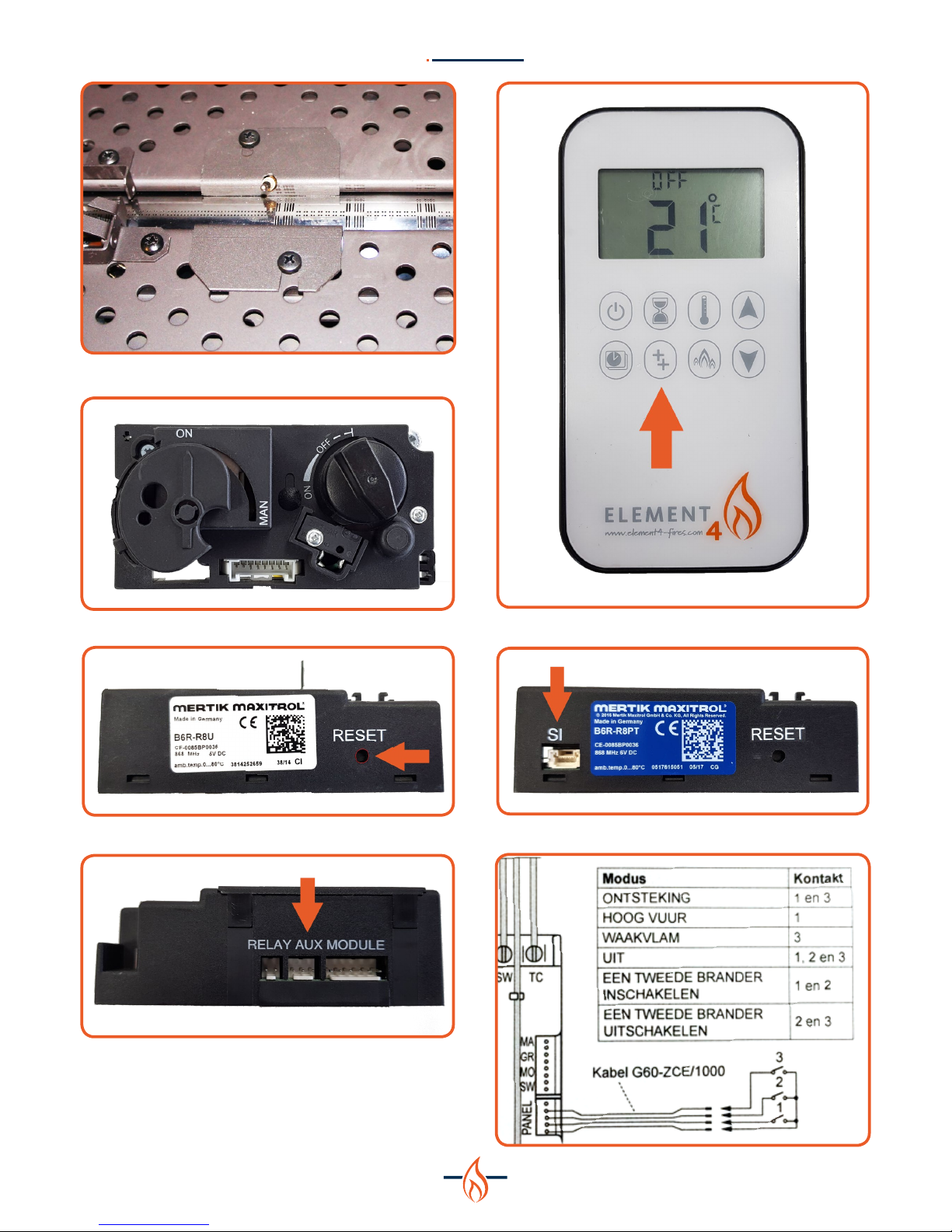
1 Decoration material blocks 2nd thermocouple Leave the space around and at the 2nd thermocouple free of
decorative material. (See Figure A-8)
2 Burner grille does not fit well with the 2nd
thermocouple
Position burner grate
3 Airflow in the burner chamber causes a restless
fire image
Check drain configuration
Fit a flue gas limiter
I Receiver gives 3
short beeps aer
each command:
1 Batteries in the receiver are empty Replace the batteries4x 1.5V AA
J Pilot is on but the
main burner does
not start working:
1 Gas valve is on manual Set Knob A must be in the ON position
K Double burner
does not work:
1 RESET the receiver Briefly press the RESET button and the receiver sounds 1 beep
(See Figure A-10)
2 Wiring loose on the receiver Click the plug in the AUX position on the receiver.
(See Figure A-11)
3 Solenoid valve does not switch Replace the solenoid valve.
Tip: only connect a new valve to the receiver first
4 Remote defective. Check if the AUX symbol is on the display when you press the
PLUS PLUS key on the remote. (See Figure A-12)
L No response from
the receiver when
the fireplace
is started via
smartphone or
tablet.
Disconnect the Wi-Fi box from the receiver
Click the plug from the SI connection on the receiver (See
Figure A-13)
Tip: Reset the home router
If the fireplace now functions normally, check the Wi-Fi settings
M Hearth does
not respond via
Domotica system
Disconnect the cabling on the Domotica system and start the
fire with the hand transmitter
When the fireplace now reacts normally, the problem is in the
Domotics
Page 23
23
APPENDICES
Figure A-8: Second thermocouple
Figure A-9: Button A on “On”
A
Figure A-13: SI-entrance
Figure A-11: Aux-position receiver
Figure A-10: RESET-button
Figure A-14: Domotica system
Figure A-12: “Doubble plus”-button on the remote
Page 24

24
APPENDICES
Error
code
Message in App Description Possible cause
F02 Contact service 5 sec beep van de ontvanger.
Geen reactie van ontvanger, en geen ontsteking.
• No engine end stop
• Wiring motor
• Microswitch
• Knob B
F03 Contact service 5 seconds beep from the receiver.
Ignition process is interrupted
No response from receiver, and no ignition.
Thermocouple wiring not in order / interrupted
F04 Ignition failure. wait 1
minute, than try again.
No pilot flame within 30 sec.
Aer 3rd attempts F06
• No gas
• Air in the pipe
• No spark
F06 Contact service 3rd time start attempt within 5 minutes • No gas
• Air in the pipe
• No spark
F10 Contact service Pilot is on
2nd thermocouple procedure
Starting again aer 2 min
• 2nd thermocouple is not heated
• 2nd thermocouple blocked by decoration material
F12 Contact service Motor turns to pilot light position • Receiver above 60 °
F13 Contact service Motor turns to pilot light position • Receiver above 80 °
F14 Contact service 5 sec. beep
No reaction from the fireplace and no ignition
• Wiring not in order
• 2nd thermocouple interrupted
• No right recipient
F15 Contact service 5 sec. beep
No reaction from the fireplace and no ignition
• 2nd thermocouple not connected
• Wiring 2nd thermocouple
F16 Hand transmitter out of
reach
No temperature in the app • Hand transmitter out of reach for more than 1.5 hours.
• Electrical fault
F17 Contact service No ignition
No reaction from the fireplace
• Voltage above 7.5 volts
• AC adapter defective
F19 Contact service Pilot flame goes out when the main burner is
opened
• 1st Thermocouple voltage not suicient
• 1st thermocouple defective
• Too low pressure
• Resistance in the thermocouple circuit
• Gas control block (magnetic coil)
F26 Contact service No high flame regulation possible • Receiver above 60 °
F28 On-Demand pilot Pilot flame goes out • Pilot flame goes out aer there has been no motor
movement for a long time.
F31 Contact service No reaction from the fireplace
No control possible by the electronics
• Receiver defective
F41 Controleer Wi-Fi No reaction from the fireplace • No Wi-Fi connection
F43 No receiver connected.
Contact service
No reaction from the fireplace
No control possible by the electronics
• No communication between receiver and Wi-Fi
module
F44 Contact service No temperature display in the App
“N.a.” in the App
• No hand transmitter connected
• Batteries hand transmitter empty
B Errors codes Procontrol App
Page 25

25
APPENDICES
Error
code
App Message Time Description Possible Cause
F04 F04 4 sec. 5 seconds beep from the receiver.
No response from receiver, and no
ignition.
No engine end stop
Wiring motor
Microswitch
Knob B
F06 F06 4 sec. 3rd time a start attempt within 5 minutes No gas
Air in the pipe
No spark
F09 F09 4 sec. No reaction from the fireplace.
No electronic control
The torque of the hand transmitter and receiver
did not work
F40 Battery symbol
Contact service
Continu Battery voltage in the hand transmitter
too low
Replace batteries
2x 1.5 V AAA
F46 F46 4 sec. No reaction from the fireplace
Interrupted responses
No electronic control
No or bad connection between the receiver and
hand transmitter
No voltage on the receiver
Low communication range, AC adapter
Page 26
26
APPENDICES
C Faults and error codes in the remote
This appendix can be consulted when error messages occur in
the application for smartphone and tablet.
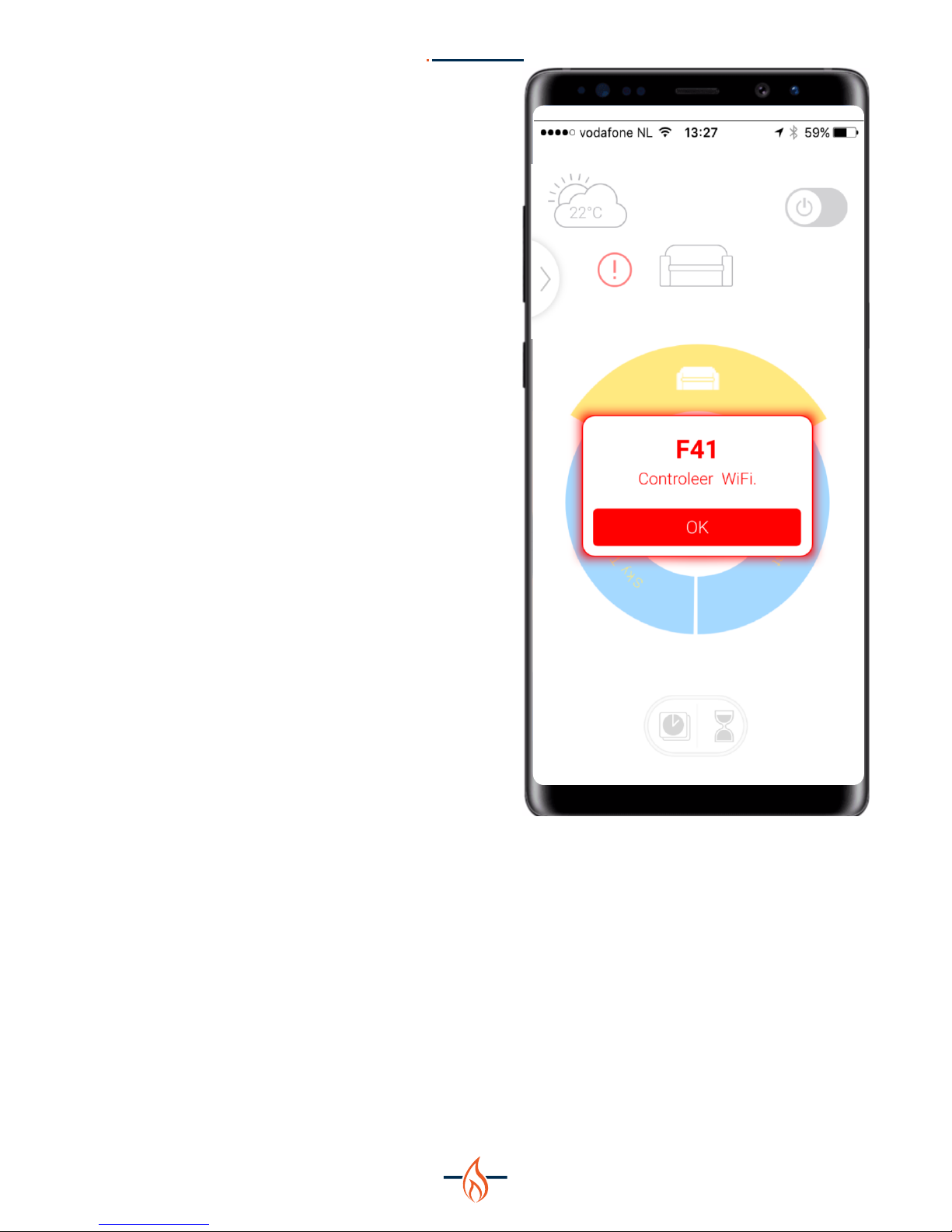
F41 error
This message will appear if there is no or bad Wi-Fi reception,
this can be between app and router or Wi-Fi box and router
App
By closing the App and opening it again, this is solved in most
cases.
Cause
The cause may be that the ProControl module is blocked or is
too far away from the router.
See: router information.
Possible solution
Only place an external router for the ProControl module
Strengthen existing Wi-Fi signal
Resetting the router.
C.1 Router information
Minimum requirement
• Compatible with IEEE 802.11n / g / b
• WPA2 encryption
• Radio frequency 2.4 GHz band
• Wireless automatic channel: Automated search for WLAN
radio channel that is free from interference.
• Support for the User Datagram Protocol (UDP)
C.2 Wi-Fi Router
It is important to think carefully about the location of a router.
This device spreads the wifi signal in and around your home.
Therefore, preferably choose a central position. You prevent
long distances from occurring. Many people put the router in
the meter cupboard, because that is where the internet comes
in at many households. A bad choice! For a powerful WiFi signal,
the router needs as much space as possible. Therefore, do not
place the device near a wall or on the ground. Some routers
have multiple antennas that you can target. Try to spread these
antennas so that you increase the range.
C.3 Jammers
Many devices also emit radio waves just like your router. These
include microwave ovens, wireless doorbells, baby monitors,
Bluetooth adapters, wireless music systems, DECT telephones
and security cameras. These devices can disrupt your wireless
network (interference), so the Wi-Fi connection is not optimal.
Try to keep jammers as far away as possible from the router.
Neighboring wireless networks also play a role in the Wi-Fi area.
C.4 2.4 or 5 GHz band?
By default, most routers use the 2.4 GHz band to broadcast the
Wi-Fi signal. The disadvantage is that this frequency band is
very busy, so that there is quickly interference. There are a lot
of competing users and jammers using the same radio waves.
Since most “older” laptops, smartphones, tablets and other
devices can not connect via the 5GHz band, the ProControl
module is not suitable for 5GHz band.
Figure C-1: Application screen
Page 27
27
APPENDICES
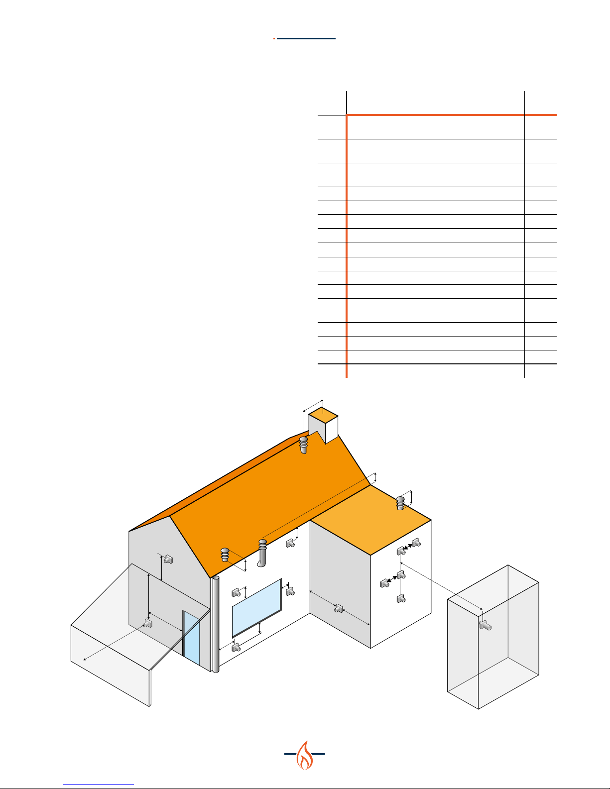
Position terminal dist.
(mm)
A* Directly below an opening, ventilation stone,
casement window etc.
600
B
Above an opening, ventilation stone, casement
window etc.
300
C
In addition to an opening, ventilation stone,
casement window etc.
400
D Under gutters or drain pipes 300
E Under eaves 300
F Under balconies or roofs of open garages 600
G From a vertical drain pipe 300
H
From an inside or outside corner 600
I Above ground roof or balcony level 300
J From a surface opposite the tip 600
K From an end opposite the tip 600
L
From an opening in the open garage (eg door,
window in the house)
1200
M Vertically from one end to the same wall 1500
N Horizontally from one end to the same wall 300
P From a vertical structure on the roof 600
Q Above the intersection with the roof 150
D Location terminal
“Distance” = minimum distance required to position the exhaust
in order to prevent adverse eects in relation to;
1. A ventilation opening of a used room, toilet or bathroom
2. Supply of heated air when the supply flows through a used
room.
3. A window that can be opened and located in the vicinity of
a used room, toilet or bathroom.
To prevent adverse eects Distance:
Exhaust A, B or C
------------------------------------------------------------------------------------At the same roof level > 6m *
At a dierent roof level > 3m * and **
On a lower wall > 2m *
On a higher sloping surface > 6m ***
At which;
* = If the required distance is not feasible, the rules regarding the
exit position have priority.
** = If the exhaust is placed at least one meter higher than the
inlet opening, or a window that can be opened.
*** = If the required distance is not feasible, the exhaust must be
placed at least one meter above the highest façade / roof.
P
Q
Q
Q
C
D,E
A
B
J
J
F
I
Q
N
M
K
H
H
Figure D-1 - Location of terminal
Page 28
28
APPENDICES
The first 3 type N bends (from vertical to horizontal) do not need
to be included in your calculations. The next type N bends are
each calculated as 1 horizontal meter in the THS.
For a type Q bend (horizontal to horizontal) the following applies:
• 90° bend in the horizontal section counts as 2 horizontal
meters in the THS.
• 45° bend in the horizontal section counts as 1 horizontal
meter in the THS
Extraction sections in a 45° upward pipe:
• 45° upward sections are calculated both vertically and
horizontally.
E General rules for ue gas extraction
E.1 Power-Fan
For flue configurations that do not function on natural dra,
the Power-Fan can be used. A maximum discharge length of 36
meters horizontally and vertically together is then possible.
For extensive installation instructions and the operation of the
Power-Fan we refer to the manual of the Power-Fan.
E-2 Determining the ue gas extraction diameter:
The general rule is that you must always adhere to a flue diameter
of 200/130. You always start with a vertical length of ½ meter
Except :
• When the stove flue pipe connection is 150/100 mm.
• when your flue only gradates vertically, in which case you
may taper directly onto the stove, to a diameter of 150/100.
• (Barring category 3 stoves)
Determining maximum vertical length:
If you have tapered your flue gas extraction as per the above,
to a diameter of 150/100, then the total maximum permitted
vertical length of your flue gas extraction is 11 meters. If you are
using a diameter of 200/130 then your maximum total length is
22 meters.
Determining maximum horizontal length:
In order to ascertain whether your intended extraction shall
function properly, a stove category is determined.
Aer you have determined in which category your fire falls, you
search for the corresponding calculation tables.
Each category refers to a table. Each appendix has two tables:
1. A table for horizontal outlet.
2. A table for vertical outlet
You must use the table applicable to you. You calculate your
total vertical section (TVS) as well as your total horizontal section
(THS). In the table you will find advice; TVS on the vertical axis
and THS on the horizontal axis.
Calculating the Total Vertical Section (TVS):
You calculate the Total Vertical Section by adding up all vertical
upward sections in the extraction gradation.
Calculating the Total Horizontal Section (THS):
You calculate the Total Horizontal Section by adding up all
horizontal parts in the extraction gradation.
Beware of bends!
Bends provide no extra resistance in the system and must
therefore be included in the TVS and THS.
There are 2 bend types:
• 45° and 90° bends from vertical to horizontal and vice versa.
(Type N)
• 45° and 90° bends from horizontal to horizontal (Type Q)
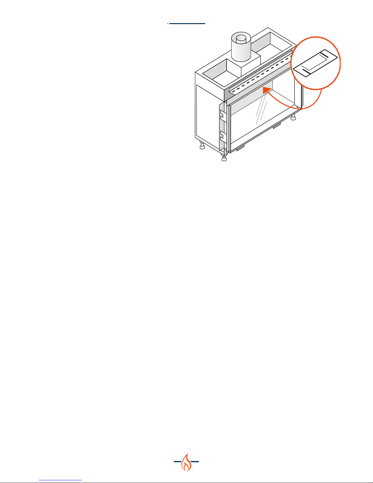
Afbeelding E-1: Position of the reduction plate
Page 29
29
APPENDICES
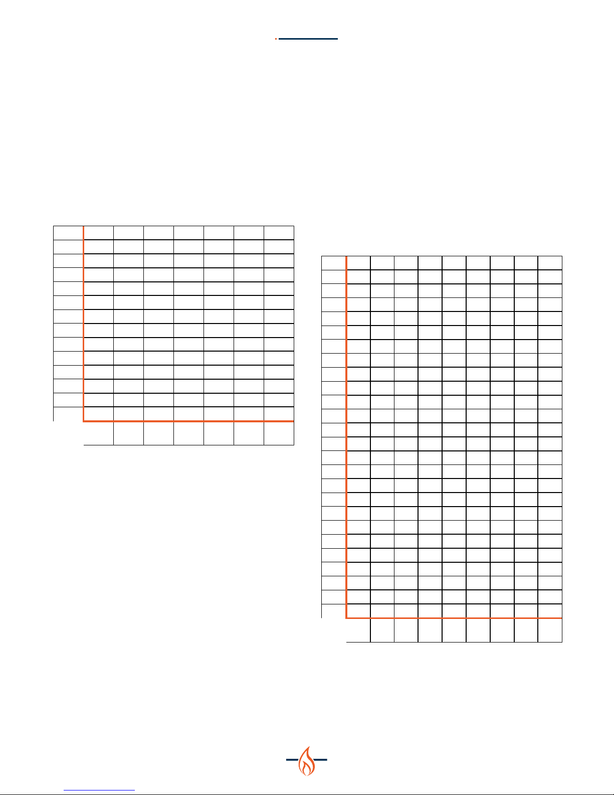
F.1 Calculation table of horizontal ue diameter 200/130 F.2 Calculation table of vertical ue diameter 200/130
With a roof terminal the minimal vertical height should be one
meter!
F Calculation table ue gas limiter
The calculation table shows when you need to place a flue gas
limiter
Result Action
0 No ristrictor required
35 Position the resitrictor
x No good operation guaranteed *
* Perhaps the powerfan is a good solution here.
10 35 35 35 35 35 0 0
9 35 35 35 35 35 0 0
8 35 35 35 35 35 0 0
7 35 35 35 35 35 0 0
6 35 35 35 35 35 0 0
5 35 35 35 35 35 0 0
4 35 35 35 35 35 0 0
3.5 35 35 35 35 35 0 0
3 0 0 0 0 0 0 0
2.5 0 0 0 0 0 0 x
2 0 0 0 0 0 x x
1.5 0 0 0 0 x x x
1 0 0 0 x x x x
0.5
x 0 x x x x x
TGV/
THG
0 0.5 1 1.5 2 2.5 3
22 0 x x x x x x x x
21 35 35 0 x x x x x x
20 35 35 35 35 0 x x x x
19 35 35 35 35 35 35 0 0 0
18 35 35 35 35 35 35 0 0 0
17 35 35 35 35 35 35 0 0 0
16 35 35 35 35 35 35 0 0 0
15 35 35 35 35 35 35 0 0 0
14 35 35 35 35 35 35 0 0 0
13 35 35 35 35 35 35 0 0 0
12 35 35 35 35 35 35 0 0 0
11 35 35 35 35 35 35 0 0 0
10 35 35 35 35 35 35 0 0 0
9 35 35 35 35 35 35 0 0 0
8 35 35 35 35 35 35 0 0 0
7 35 35 35 35 35 35 0 0 x
6 35 35 35 35 35 35 0 0 x
5 35 35 35 35 35 35 0 0 x
4 35 35 35 35 35 35 0 x x
3.5 35 35 35 35 35 35 0 x x
3 0 0 0 0 0 0 0 x x
2.5 0 0 0 0 0 0 x x x
2 0 0 0 0 0 x x x x
1.5 0 0 0 0 x x x x x
1 0 0 0 x x x x x x
0.5
x 0 x x x x x x x
TGV/
THG
0 0.5 1 1.5 2 2.5 3 3.5 4
F.3 Calculation table vertical ue diameter 150/100
If the channel is only vertical, you may reduce to a diameter of
150 / 100mm, similar to the hearth. If you reduce, you do not
need to use a flue gas reduction plate.
Page 30

30
APPENDICES
G Technical data
The dataplate specifies for which type of gas, gas pressure and
for which country this appliance is intended. The nameplate is
attached to a chain. It must remain attached to the chain.
Note: Check whether the appliance is suitable for the gas type
and gas pressure on site.
Gas type ▶ NATURAL GAS LPG
Country of use ▶
AT,BG,CH
DK,ES,FI
GB,GR,HR
IE,IT,LT
LV,NO,PT
RO,SE,SI
SK,TR
DE,LU
PL BE,FR DE NL
BG,DK,EE
FI,GB,GR
HU,HR,IT
LY,MT,NL
NO,RO,SE
SI,SK,TR
AT,CH
CZ,DE
AT,BE,CH
CZ,DE,ES
FR,GB,IE
IT,NL,PT
SK,TR
CZ,LT
NL,SK
Gas Category ▶ I2
H
I2
E
I2
E+
I2ELL I2L/ I2
EK
I3
B/P
I3
B/P
I3+ I3+
Unit G20 G20 G20/G25 G20/G25 G25/G25,3 G30/G31
Supply pressure mbar 20 20 20 / 25 20 25 30 50 28 - 30/37 30
Burner pressure mbar 15,8 28,1
Gross input kW
13,5 13,5 13,5 / 12,5 12,5 12,5 13
Net input kW 12,2 12,2 12,2 / 11,3 12,2 11,3 12,0
max. Heat output kW 10,8 10,8 10,8 / 10,0 10,8 10,0 10,7
min. Heat output kW 3,6 3,6 3,6 / 3,3 3,6 3,3 3,6
(Max.) Gas usage m3/uur 1,25 1,25 1,25 / 1,34 1,2 1,34 0,36
NOx mg/kWh
input
<100 <100
Pilot 440-1350-312 440-1350-271
Burnerinjection
650 (Front), 560 (Rear) 220 (2X)
* i.e. I2
(43.46 -45.3 MJ/m3 (0°C))
Additional electricity use
At rated heat output
el
max
9-5kW
With minimal heat emission
el
min
9-5kW
In standby mode
el
sb
9-5kW
Power requirement for the permanent pilot light
Power requirement for the permanent pilot
light (requirements applicable)
P
pilot
Does not
apply
Eiciency (NCV)
Eiciency at rated heat output η
th, nom
89 %
Eiciency at min. heat output (indicative) η
th, min
58 %
Type of heat release / control room temperature (Select one)
With electronic control of the room temperature plus week switch
Other control options
Control of the room temperature with presence detection
Control the room temperature with open window detection
With the option of remote control
With adaptive control of the start
With limitation of the operating time
Page 31
31
APPENDICES
*Same values go for the Optica
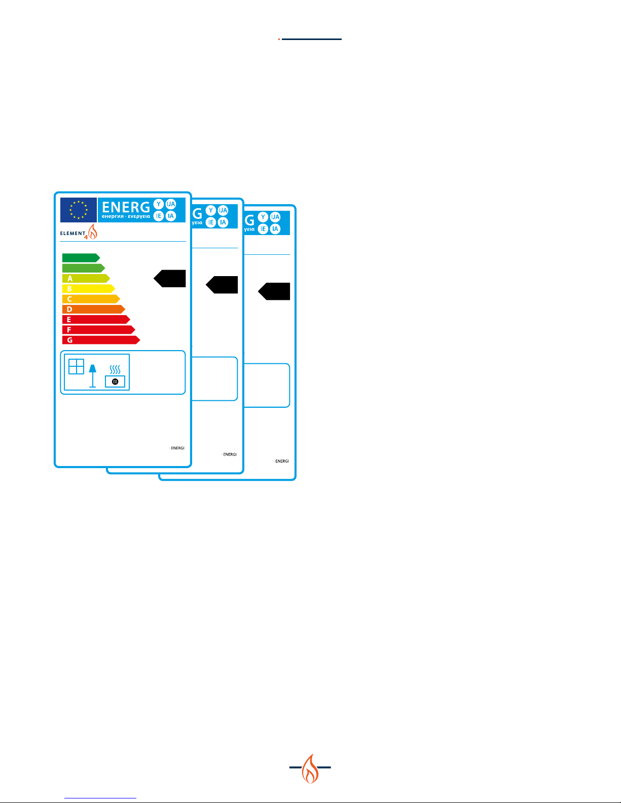
H Ecodesign
Since 1 January 2018 every fireplace has been provided with
an eco-label which is always supplied with the fireplace. The
ecolabel shows which category the fireplace belongs to.
H.1 Ecolabels
The ecolabels for the dierent types of gas are indicated below,
respectively G20, G25 and G30.
Bioptica
A
+
A
B
C
D
E
F
G
2015/1186
kW
ENERGIA · ЕНЕРГИЯ · ΕΝΕΡΓΕ ΙΑ · ENERGIJA · ENERGY · ENERGIE
A
++
A
+
A
+++
A
++
A
+
A
Modore 75H | G30
10,7
A
+
A
B
C
D
E
F
G
2015/1186
kW
ENERGIA · ЕНЕРГИЯ · ΕΝΕΡΓΕ ΙΑ · ENERGIJA · ENERGY · ENERGIE
A
++
A
+
A
+++
A
++
A
+
A
Modore 75H | G25
10,0
A
+
A
B
C
D
E
F
G
2015/1186
kW
ENERGIA · ЕНЕРГИЯ · ΕΝΕΡΓΕ ΙΑ · ENERGIJA · ENERGY · ENERGIE
A
++
A
+
A
+++
A
++
A
+
A
Modore 75H | G20
10,8
Page 32
32
APPENDICES
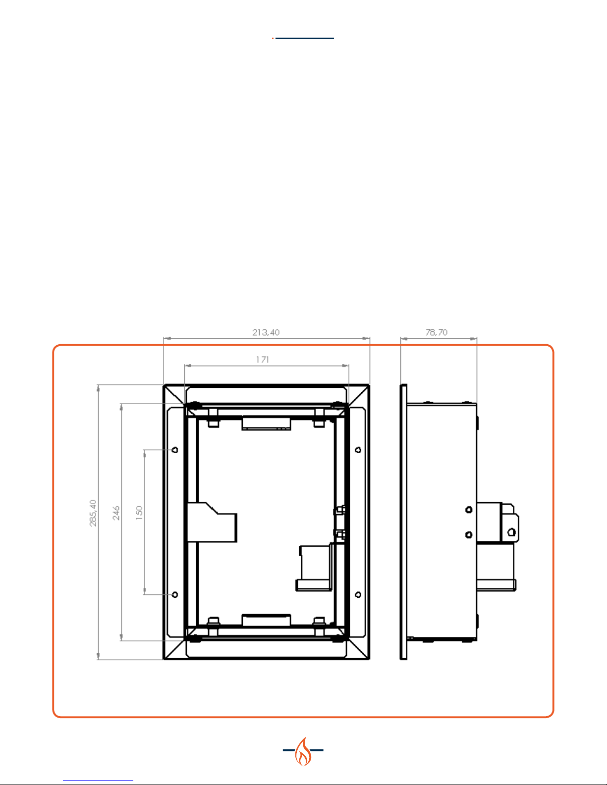
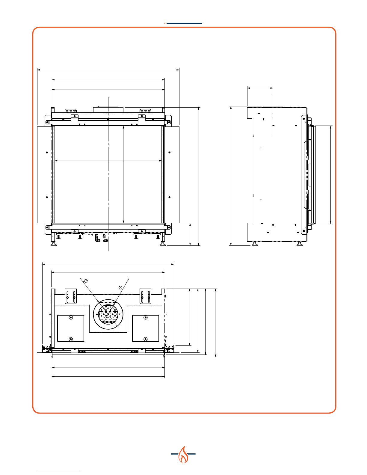
I Dimensional drawings
On this page and the following ones you will find dimensional
drawings of the Cupido models and accessories with some of
the important dimensions that you have to take into account
when installing and installing your fireplace.
Figure I-1: Service hatch, BDLE4
Page 33
33
APPENDICES
172
933
656
880
458
760
2
0
0
1
3
0
380
427
442
754
754
754
950
651
925
716
754
150 min
Afbeelding I-2: Technical drawing Modore 75H
Page 34

34
APPENDICES
Page 35

35
APPENDICES
Page 36
Paxtonstraat 23
8013 RP Zwolle
The Netherlands
www.element4-fires.com
ELEMENT 4 B.V.
APRIL 2018
 Loading...