

Element4 Lucius 140 Room Divider, Lucius 140 Tunnel, Lucius 140 1/3, Lucius 140 2/3 Installation Manual
Page 1
Installation Manual
Lucius 140 Room Divider
Lucius 140 Tunnel
Lucius 140 1/3
Product
Information
Lucius 140
Promotional Video
Lucius 140 2/3
Direct Vent
Gas Fireplaces
HOT GLASS WILL Une surface vitrée chaude
CAUSE BURNS. peut causer des brûlures.
DO NOT TOUCH GLASS Laisser refroidir la surface
UNTIL COOLED. vitrée avant d’y toucher.
NEVER ALLOW CHILDREN Ne permettez jamais á un enfant
TO TOUCH GLASS. de toucher la surface vitrée.
A barrier designed to reduce the risk of burns from the hot viewing glass is provided with this appliance and shall be installed
for the protection of children and other at-risk individuals.
Une barrière conçu pour réduire le risque de brûlure par le verre de visualisation chaude est fournie avec cet appareil et doit
être installé pour la protection des enfants et autres personnes à risque.
WARNING:
FIRE OR EXPLOSION HAZARD
Failure to follow safety warnings exactly could
result in serious injury, death, or property damage.
AVERTISSEMENT:
INCENDIE OU D’EXPLOSION
Le non-respect des avertissements de sécurité à la
lettre pourrait entraîner de graves blessures , la mort
ou des dommages matériels.
- Do not store or use gasoline or other ammable
vapors and liquids in the vicinity of this or any
other appliance.
- WHAT TO DO IF YOU SMELL GAS
• Do not try to light any appliance.
• Do not touch any electrical switch; do not
use any phone in your building.
• Leave the building immediately.
• Immediately call your gas supplier from a
neighbor’s phone. Follow the gas supplier’s
instructions.
• If you cannot reach your gas supplier, call
the re department.
- Installation and service must be performed
by a qualied installer, service agency or the
gas supplier.
INSTALLER: Leave this manual with the appliance.
CONSUMER: Retain this manual for future reference.
Element4 Gas Fireplaces EuropeanHome.com
- Ne pas entreposer ni utilizer d’essence ni d’autres vapeurs
ou liquides inammables dans le voisinage de cet appareil
ou de tout autre appareil.
- QUE FAIRE SI VOUS SENTEZ UNE ODEUR DE GAZ
• Ne pas tenter d’allumer d’appareil.
• Ne touchez á aucan interrupteur. Ne pas vous servir des
téléphones se trouvant dans le bátiment ou vous trouvez.
• Quitter immédiatement le bâtiment.
• Appelez immédiatment votre fournisseur de gaz depuis
un voisin. Suivez les instructions du fournisseur.
• Si vous ne pouvez rejoindre le fournisseur de gaz
appelez le service des incindies.
- Installation et l’entretien doivent être effectués par un
installateur qualié, une agence de service ou le fournisseur
de gaz.
INSTALLATEUR: Laissez cette notice avec l’appareil.
CONSOMMATEUR: Conservez cette notice pour
consultation ultérieure.
October 2, 2015
1
Page 2

TABLE OF CONTENTS
Important Safety Information 3
User Information 6
Specications and Dimensions 7
Lucius 140 Room Divider 9
Lucius 140 Tunnel 10
Lucius 140 1/3 11
Lucius 140 2/3 12
Parts of the Fireplace 13
Clearances 15
Gas and Electric 22
Venting 23
Horizontal 25
Vertical 28
Restrictors 32
Enclosing the Fireplace 33
Non- combustible Materials List 33
Convection Air Opening 34
Rough Opening Dimensions 37
Operating the Fireplace 42
Installing the Fire Media 46
Screen Installation 48
Maintenance 55
Glass 55
Burner 57
Pilot 57
Thermocouple 58
Venting 58
Replacement Parts 58
Warranty 59
Massachusetts Certication Appendix One
Troubleshooting Flowchart Appendix Two
LP Conversion Appendix Three
Installing the Optional Wall Switch Appendix Four
Index ---
Page 3
IMPORTANT SAFETY INFORMATION
CAUTION - HOT! HOT! HOT!
This appliance is a HEATING appliance and it does become very hot in operation.
UNDER ANY CIRCUMSTANCES, DO NOT PLACE any object, furniture, draperies or other item LESS THAN 36”/90 cm IN
FRONT OF THE GLASS OF THE FIREPLACE.
CHILDREN AND PETS
Radiant heat can heat surfaces such as the surround and trims of the replace to temperatures that, although approved
safe, can be quite uncomfortable to touch - particularly for children and pets. Children and pets should always be
supervised when in the room where the appliance is located. Remote control handset should be kept out of reach of
children. In the presence of children, we STRONGLY RECOMMEND that you install in front of the replace: a re screen or,
to protect young toddlers, a “hearth gate”.
HOT SURFACES
Be aware that, although safe, some combustible materials and
nishes, even though installed at listed clearances may, over time,
discolor, warp or show cracks.
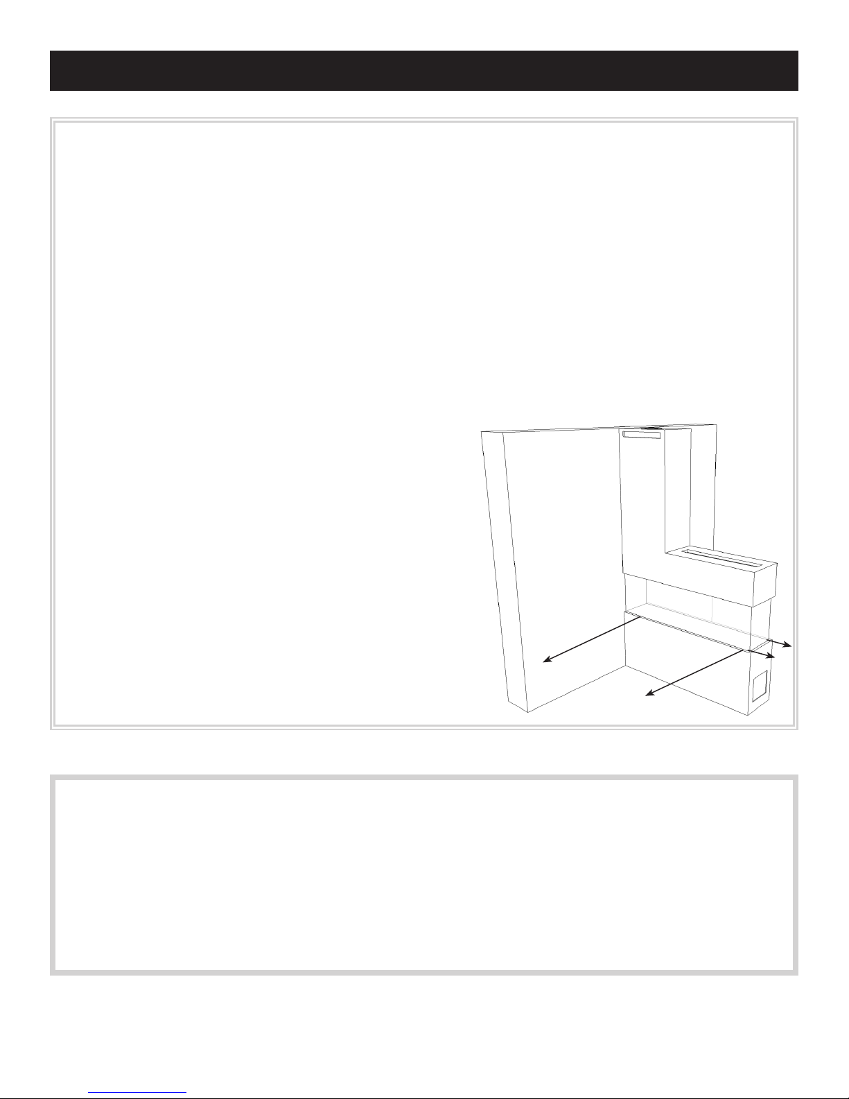
Convective heat will exit the unit and travel up the wall surface if not
impeded. Protruding mantels and projections can help direct the
heat away from the wall. AVOID placing heat sensitive items such as
televisions, paintings, decorations, etc. above replaces or near the
edge of protrusions unless appropriate.
Do not place furniture or other
objects within 36” of the replace
glass.
SAVE THESE INSTRUCTIONS
Make yourself fully aware of all the following instructions and the many features of the Element4
direct vent gas replace appliance.
INSTALLER: Leave this manual with the appliance.
OWNER: Keep this manual for future reference.
Element4 Gas Fireplaces EuropeanHome.com
3
Page 4

IMPORTANT SAFETY INFORMATION
WARNING
Children and adults should be alerted to the hazards of
high surface temperature and should stay away to avoid
burns or clothing ignition.
WARNING
This direct vent system appliance must be installed as an
OEM installation in manufactured homes (USA only) or
an aftermarket permanently located, or a mobile home,
where not prohibited by local codes and must be
installed in accordance with Manufacturer’s instructions
and the Manufactured Home Construction and Safety
Standard, Title 24 CFR, Part 3280, in the United States, or
the Standard for Installation in Mobile Homes, CAN/CSA
Z240 MH Series, in Canada.
WARNING: Installation and Service
Installation and service must be performed by an
authorized qualied installer, service agency or gas
supplier.
Any alteration to the product that causes soot or carbon to
form and results in damage is not the responsibility of the
manufacturer.
ONLY a qualied person may open the door/remove the
glass.
Do not modify or substitute any part of this appliance.
WARNING: Electrical Grounding
These direct vent appliances must be electrically
grounded in accordance with the local codes or, in the
absence of local codes, with National Electric code, ANSI/
NFPA 70, or the Canadian Electric Code, CSA C22.1
If the information in these instructions is not followed
exactly a re or explosion may result causing property
damage, personal injury or death.
Do not store or use gasoline or other ammable vapors
and liquids in the vicinity of this appliance.
WARNING: Glass Handling
The glass must only be removed by a qualied person.
Gloves should be worn when removing the glass.
WARNING: Gas Appliance
This appliance is only for use with the type of gas
indicated on the rating plate. These appliances are not
convertible for use with other gases unless a certied kit
is used and the conversion is performed by an authorized
qualied technician.
Applicable standards are ANSI Z21.50/CSA 2.22 (Vented
Gas Fireplaces) and CAN/CGA 2.17-M91 (Gas-red
Appliances for Use at High Altitudes.) If your installation
is at an elevation greater than 2000’ in the US or 4500’
in Canada, consult with the local authority having
jurisdiction for gas product installations to determine their
specic requirements for high altitude installations.
Element4 Gas Fireplaces EuropeanHome.com
4
Page 5
IMPORTANT SAFETY INFORMATION
This gas replace and vent assembly MUST be vented
directly to the outside and MUST NEVER be attached to a
chimney serving a separate solid fuel burning appliance.
Each gas appliance MUST BE a separate vent system.
Common vent systems are prohibited.
This unit MUST be used with a vent system as described
in this installation manual. NO OTHER VENT SYSTEM OR
COMPONENTS MAY BE USED.
INSPECT the external vent cap on a regular basis to make
sure that no debris, plants, trees, or shrubs are interfering
with the air ow.
TURN OFF the gas before servicing the appliance. It is
recommended that a qualied service technician perform
an appliance check-up/service once a year.
Any safety screen or guard removed for servicing MUST BE
REPLACED before operating this appliance.
THIS UNIT IS NOT FOR USE WITH SOLID FUEL, and must
only be used with gas supply conditions as indicated on
the rating label.
DO NOT USE this appliance if any part has been under
water. Immediately call a qualied service technician to
inspect the unit and to replace any part of the control
system and any gas control that has been under water.
NEVER OBSTRUCT the ow of ventilation air. Keep the
front of the appliance CLEAR of all obstacles and materials
for servicing and proper operation.
The glass panels MUST be in place and sealed before the
unit can be placed into safe operation.
DO NOT OPERATE this appliance with the glass panels
removed, cracked or broken. Replacement of the glass
panels should be performed by a licensed or qualied
service person. DO NOT strike or slam the glass panels.
The glass panels SHALL ONLY be replaced by units
supplied by the manufacturer. NO SUBSTITUTE panels
shall be used.
DO NOT USE abrasive cleaners on the panels. DO NOT
ATTEMPT to clean the glass panels when they are hot.
DO NOT use this appliance as a temporary source of heat
during construction.
This appliance is a vented gas replace. It must not be
used for any other purposes such as drying clothes, etc.
If the pilot ame is extinguished either intentionally or
unintentionally, no attempt should be made to re-light the
gas until at least 3 minutes have elapsed.
Dimensions will appear as INCHES”/metric throughout
this manual. For convenience, the inches are rounded to
the nearest 1/16” when converted. If greater accuracy is
required, use the metric dimensions.
Element4 Gas Fireplaces EuropeanHome.com
5
Page 6
USER INFORMATION
WARMTH AND BEAUTY HOW IT WORKS
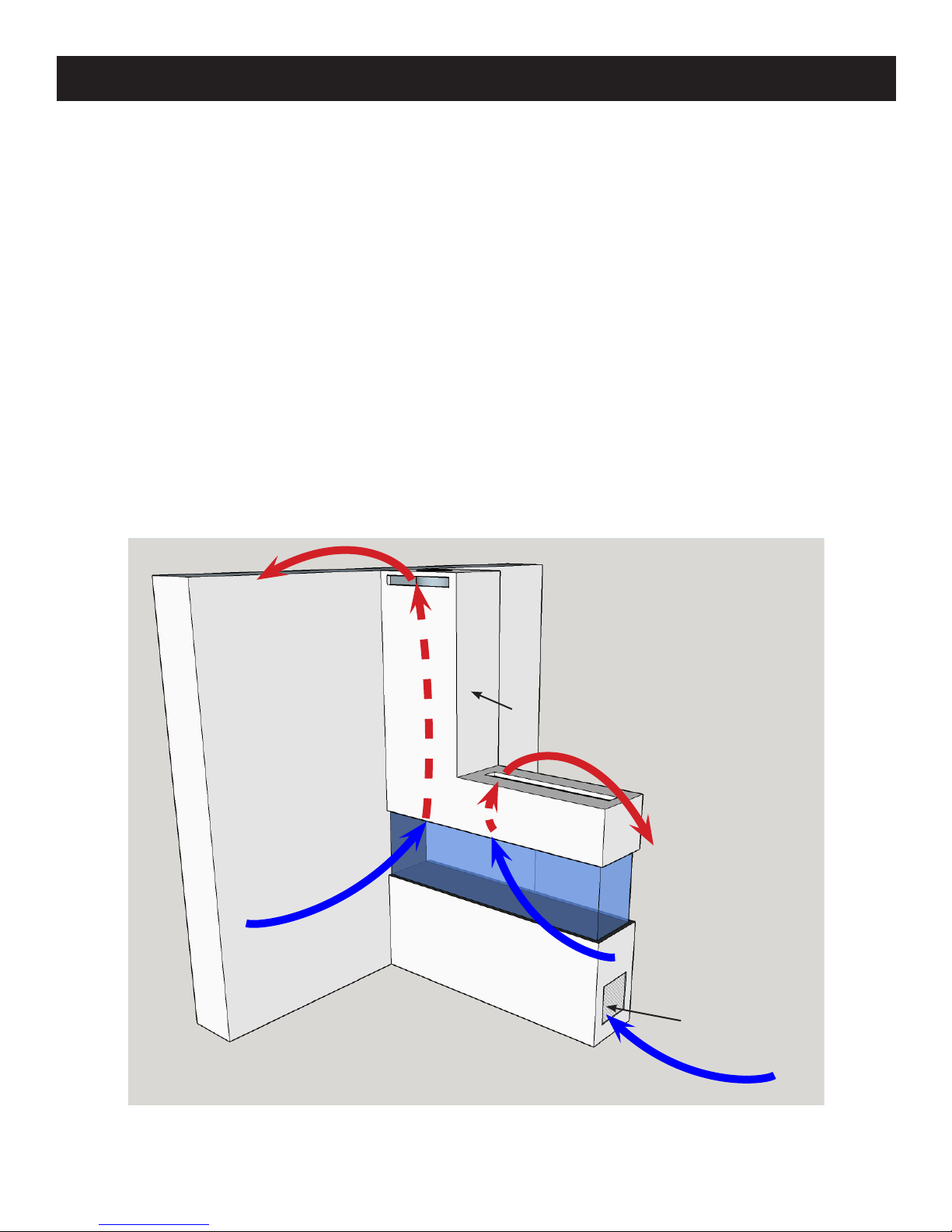
The Element4 replaces are direct vent replaces and, as such, the intake and exhaust are both handled through the vent pipe.
The replace also provides convection air to your room. Figure 1 (Lucius 140 Room Divider shown) shows one of the unique
features of the Element4 replaces - its use of warm, convection air ow.
Other replaces have louvered metal boxes around them to keep temperatures under control. The Element4 replaces use your
enclosing walls, or chase, to guide this warm air. This design, therefore, requires the use of non-combustible wall materials and
gives you beauty for your eort.
When the air within the chase is warmed by the replace, it rises and exits through the Convection Air Outlet. This air is then
replaced by room air which enters the chase just above the replace glass and through the Wall Access Door. As the exiting warm
air cools, it falls to the oor where it's drawn into the inlets and the cycle repeats.
The replace provides the inlet for room air as part of its design; you provide the warm air outlet as part of your design.
See the ENCLOSING the FIREPLACE section of this manual for more information.
Warm Air Out
Room Air In
Site-built Chase
Warm Air Out
Room Air In
Access Door
Element4 Gas Fireplaces EuropeanHome.com
Room Air In
Figure 1
6
Page 7
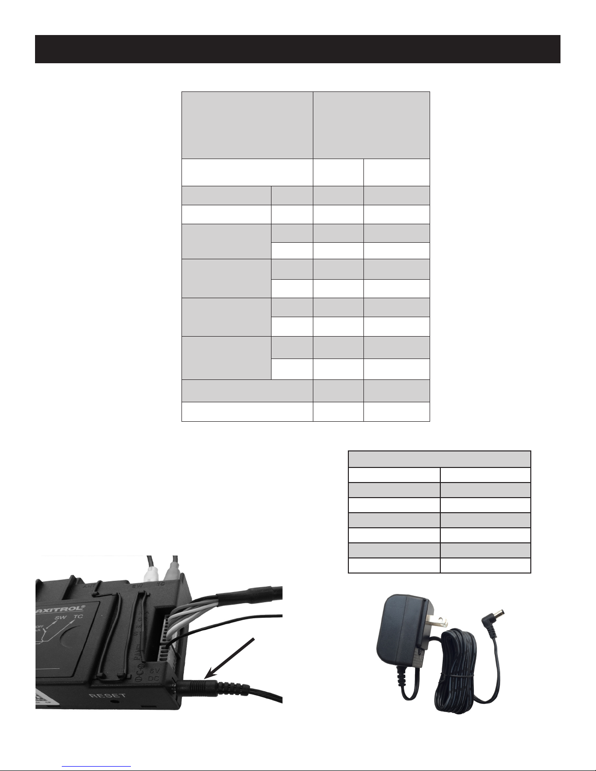
APPLIANCE RATINGS
SPECIFICATIONS and DIMENSIONS
Lucius 140 Room Divider
Model
Lucius 140 Tunnel
Lucius 140 1/3
Lucius 140 2/3
Gas
Input Maximum Btu/hr 38,200 34,100
Input Minimum Btu/hr 13,650 11,950
Maximum Supply
Pressure
Minimum Supply
Pressure
Manifold Pressure
Maximum
Manifold Pressure
Minimum
Main Burner Injector Marking 1200 380
Pilot Injector Marking 31.2 27.1
in. w.c. 7 11
kpa 1.74 2.74
in. w.c. 4 8
kpa 1 2
in. w.c. 4.0 10.8
kpa 0.99 2.68
in. w.c. 0.4 1.5
kpa 0.1 0.38
Natural
Gas
Propane
AC ADAPTER SPECIFICATIONS
Input Voltage 120 V AC
Input Power 9 W
Output Voltage 6V DC
Output Current 500 mA
Size 3.1”H x 2”W x 1.7”D
Output Cord Length 6 Feet
Agency Approvals UL, CSA
Figure 2 AC Adapter Connection (arrow)
Element4 Gas Fireplaces EuropeanHome.com
7
Page 8

SPECIFICATIONS and DIMENSIONS
DO NOT REMOVE
DIRECT VENT GAS FIREPLACE - Not for
use with solid fuel.
This appliance is only for use with the type of gas indicated on the
rating plate and may be installed in an aftermarket, permanently
located, manufactured home (USA only) or mobile home where
not prohibited by local codes. See owner’s manual for details. This
appliance is not convertible for use with other gases, unless a
certied kit is used.
For use only with Vent, Glass Panels and Ceramic Logs (or
stones) certied and approved for use with this appliance.
This appliance must be installed in accordance with local codes,
if any; if none, follow ANSI Z223.1/NFPA 54, or CSA B149.1. The
appliance must be properly connected to a venting system in accordance with the manufacturer’s installation instructions.
The system must be installed by ba qualied installing agency.
SAMPLE
Manufacturer/ Fabricant:
Element4 B.V.
Paxtonstraar 23
NL-8013 RP Zwolle
The Netherlands / Pays-Bas
Tel / Tél : 0031 38 4209020
Fax:0031 38 4209021
Product name: (check one) / Nom du produit : (cochez …)
Trisore 100H [ ] Bidore 100H [ ]
Modore 100H [ ]
Serial No. / N° de série: _____________
This appliance equipped only for altitudes /
Cet appareil est équipé uniquement pour les altitudes : 0-4500 ft / 0-1370 m
Fuel Type / Type de combustible Natural Gas / Propane Gas /
Gaz naturel Gaz propane
(check one) / (cochez…) [ ] [ ]
Max. Input / Capacité d’entrée maxi (BTU/HR) 34145 34145
Min. Input / Capacité d’entrée mini (BTU/HR) 15025 17075
Gas Inlet Pressure (in w.c.) / Pression d’entrée du gaz (en w.c.) 7 11
Manifold Pressure (in w.c.) / Pression d’admission (en w.c.) 2.1 7.4
Orice Size / Taille de l’ouverture 650 (x2) 180 (x2)
Clearances to combustible / Dégagement jusqu’au combustible :
Back / Arrière : 11” (28cm) Sides / Côtés : 11” (28cm)
Top / Haut : 26” (66cm) Floor / Sol : 4” (10cm)
Mantel / Linteau : 2” (5cm)
NE PAS RETIRER
FOYER GAZ À AÉRATION DIRECTE - Ne pas
utiliser avec un combustible solide
Cet appareil est destiné uniquement avec le type de gaz indiqué sur
la plaque signalétique et peut être installé dans une habitation en dur,
à emplacement xe (USA uniquement) ou dans une résidence mobile
si la législation locale l’autorise. Consultez le manuel du propriétaire
pour les détails. Cet appareil ne doit pas être modié pour une utilisation avec d’autres gaz, sauf à l’aide d’un kit certié.
À utiliser uniquement avec des ventilations, panneaux en verre et
poutres (ou pierres) en céramique dont l’utilisation est autorisée avec
cet appareil.
Cet appareil doit être installé conformément à la législation locale. À
défaut d’une telle législation, suivre ANSI Z223.1/NFPA 54, ou CSA
B149.1. L’appareil doit être proprement raccordé à un système de
ventilation, conformément aux instructions d’installation du fabricant.
Le système doit être installé par un installateur qualié.
Approved By / Approuvé par:
Control No. : 4006611
Conforms to std. ANS Z21.50a-2008
Certied to std. CSA 2.22a-2008 - Vented Gas Fireplaces
A typical rating label is shown in Figure 3. It is attached to every Element4 replace and contains important certication information.
It must not be removed from the replace.
Element4 Gas Fireplaces EuropeanHome.com
Figure 3 Typical Rating Label
8
Page 9
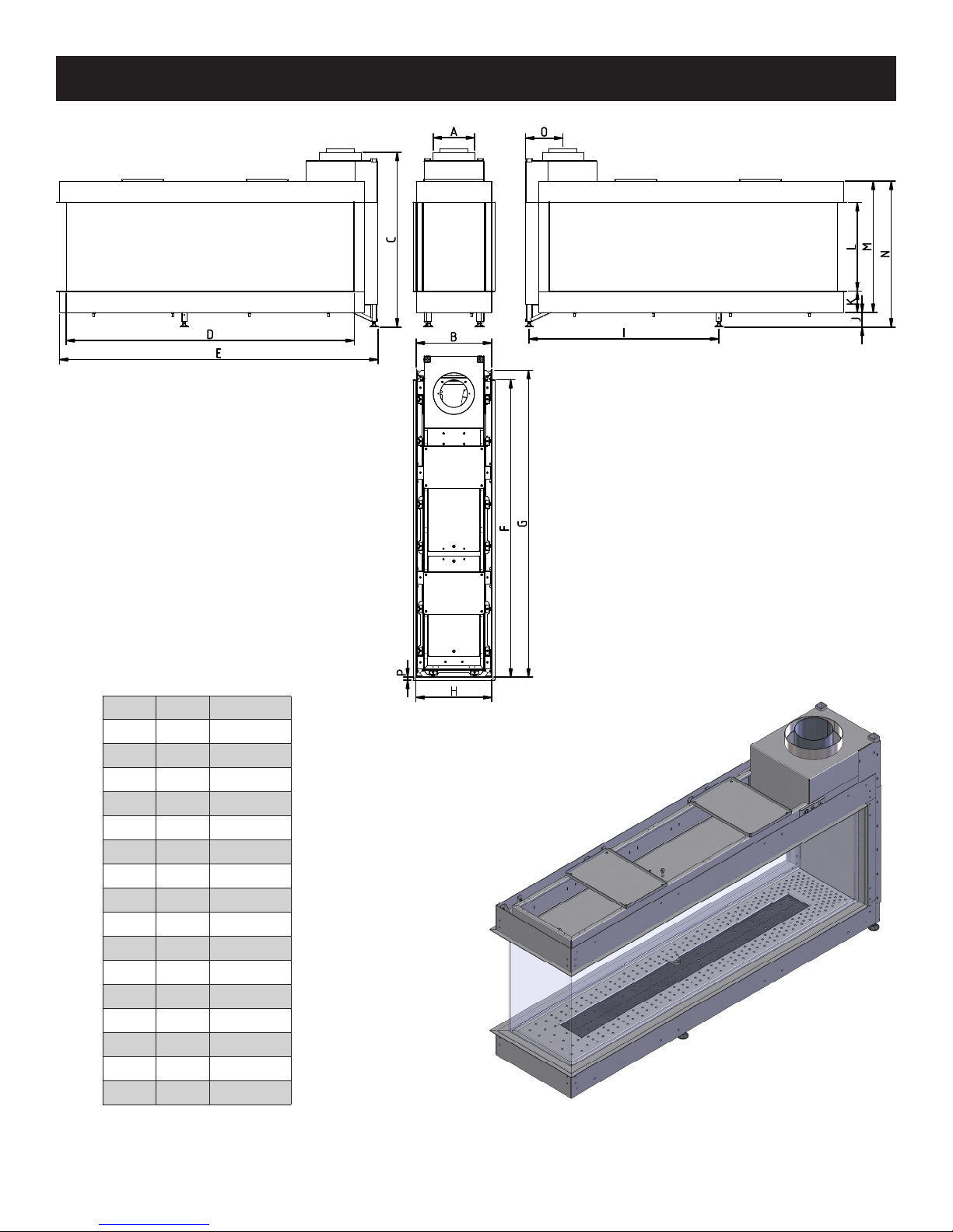
SPECIFICATIONS and DIMENSIONS
LUCIUS 140
ROOM DIVIDER
Letter Inches Millimeters
A 7⁄ 200
B 14⁄ 364
C 32⁄ 834
D 54⁄ 1389
E 60⁄ 1534
F 55⁄ 1420
G 57⁄ 1464
H 14⁄ 366
I 36 915
J 2⁄ 70
K 4 102
L 16⁄ 422
M 24⁄ 626
N 27⁄ 696
O 7⁄ 180
P ⁄ 15
LUCIUS 140 ROOM DIVIDER
Element4 Gas Fireplaces EuropeanHome.com
9
Page 10
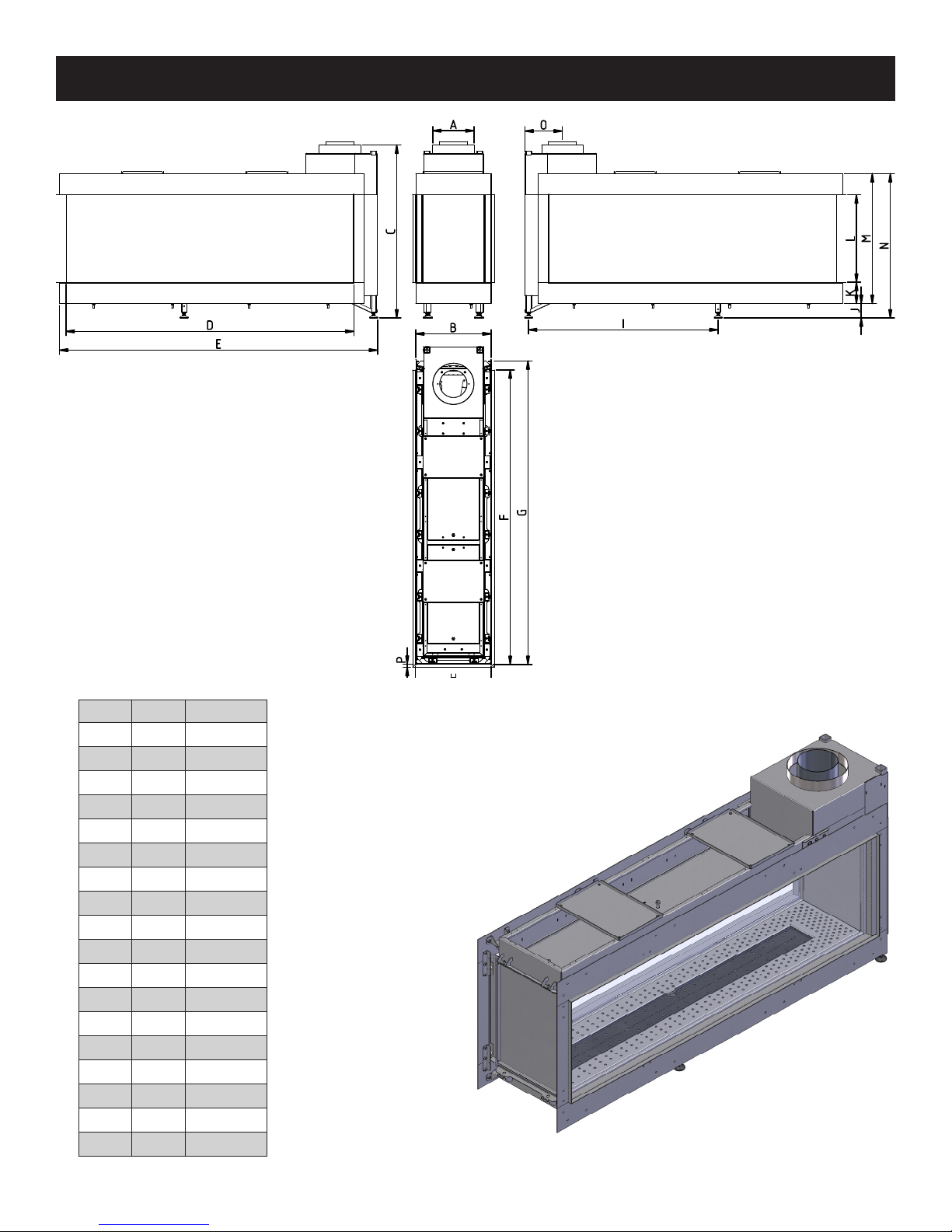
SPECIFICATIONS and DIMENSIONS
LUCIUS 140 TUNNEL
Letter Inches Millimeters
A 7⁄ 200
B 14⁄ 364
C 14⁄ 364
D 59⁄ 1509
E 55½ 1409
F 59⁄ 1509
G 55½ 1409
H ⁄ 15
I 2⁄ 70
J 32⁄ 834
K 53⁄ 1370
L 61⁄ 1554
M 37½ 953
N 4 102
O 16⁄ 422
P 24⁄ 626
Q 27⁄ 696
R 7⁄ 180
Element4 Gas Fireplaces EuropeanHome.com
LUCIUS 140 TUNNEL
10
Page 11
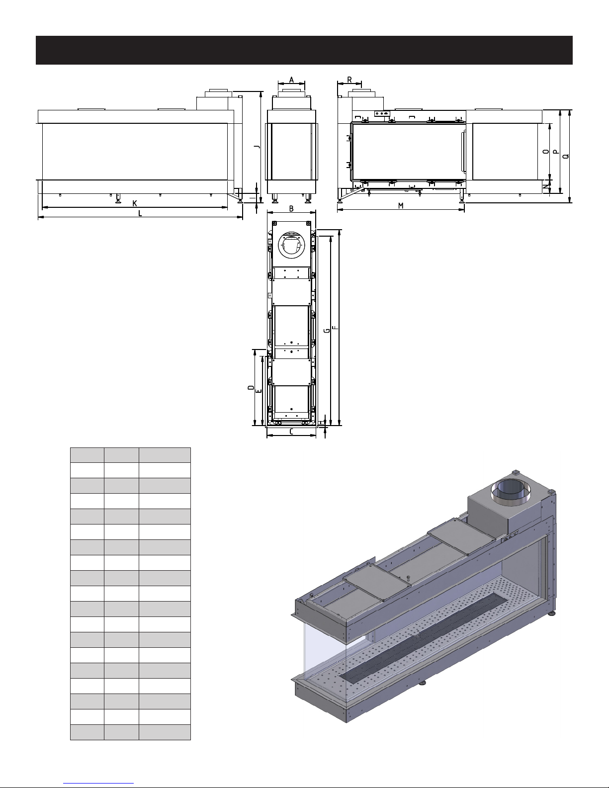
SPECIFICATIONS and DIMENSIONS
LUCIUS 140 1/3
Letter Inches Millimeters
A 7⁄ 200
B 14⁄ 364
C 14⁄ 364
D 22½ 570
E 20½ 520
F 57⁄ 1470
G 55⁄ 1420
H ⁄ 15
I 2⁄ 70
J 32⁄ 834
K 54⁄ 1389
L 60⁄ 1534
M 37½ 953
N 4 102
O 16⁄ 422
P 24⁄ 626
Q 27⁄ 696
R 7⁄ 180
Element4 Gas Fireplaces EuropeanHome.com
LUCIUS 140 C 1/3 LEFT CORNER SHOWN
11
Page 12
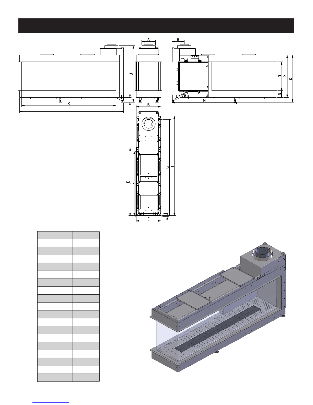
SPECIFICATIONS and DIMENSIONS
LUCIUS 140 2/3
Letter Inches Millimeters
A 7⁄ 200
B 14⁄ 364
C 14⁄ 364
D 39⁄ 1000
E 37⁄ 950
F 57⁄ 1470
G 55⁄ 1420
H ⁄ 15
I 2⁄ 70
J 32⁄ 834
K 54⁄ 1389
L 60⁄ 1534
M 37½ 953
N 4 102
O 16⁄ 422
P 24⁄ 626
Q 27⁄ 696
R 7⁄ 180
Element4 Gas Fireplaces EuropeanHome.com
LUCIUS 140 C 2/3 LEFT CORNER SHOWN
12
Page 13
SPECIFICATIONS and DIMENSIONS
PARTS OF THE FIREPLACE
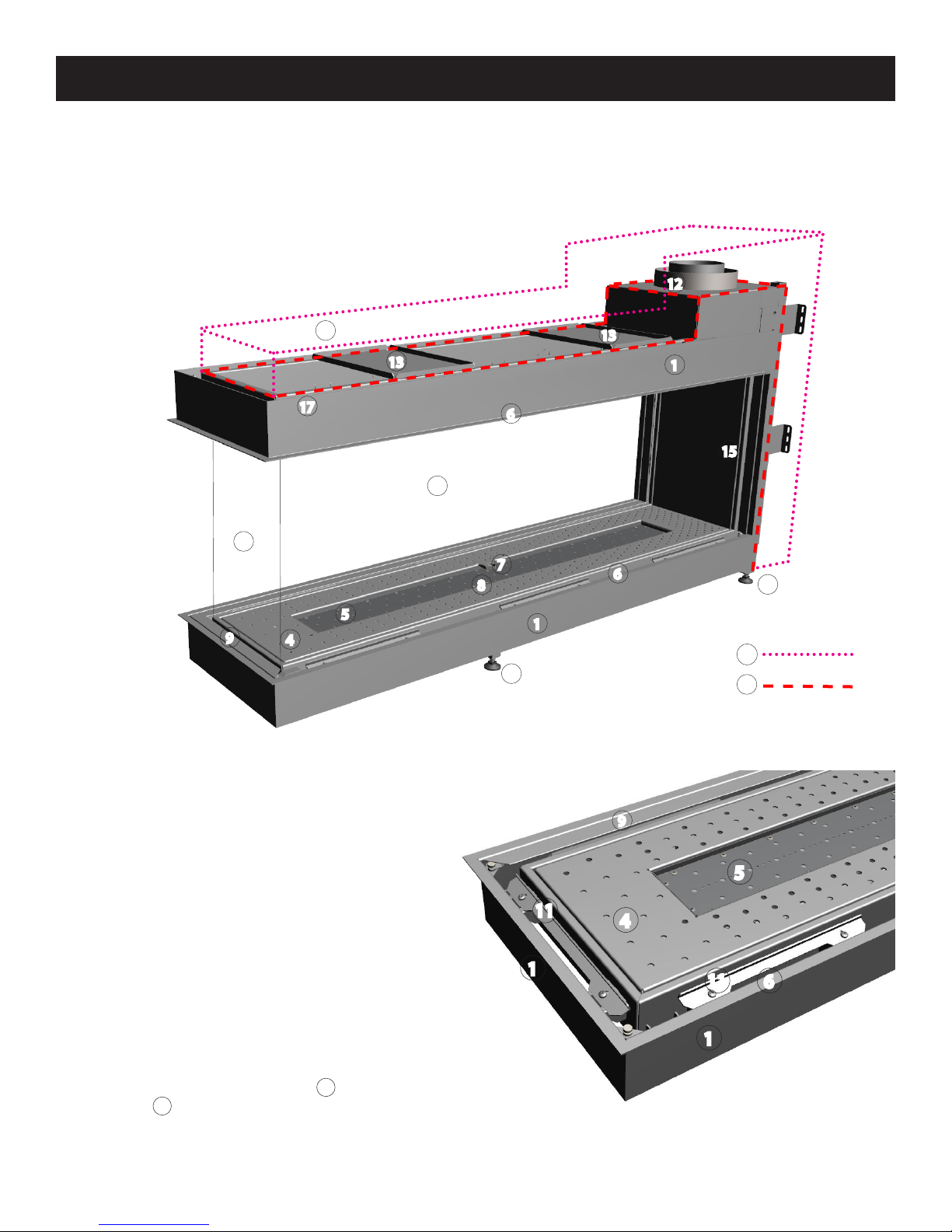
The various parts of the Lucius 140 replace are shown in Figures 4, 5 and 6. These parts are typical of any Element4 replace.
12
16
13
17
10
2
5
9
4
6
7
8
1
3
13
6
1
Figure 4
15
3
16
17
Figure 5 shows two Glass Clamps, after some of
the Finish Trim is removed.
Element4 Gas Fireplaces EuropeanHome.com
9
11
13
9
5
11
1
4
11
6
1
Figure 5
Page 14
SPECIFICATIONS and DIMENSIONS
2
1
14
13
8
13
3
Figure 6
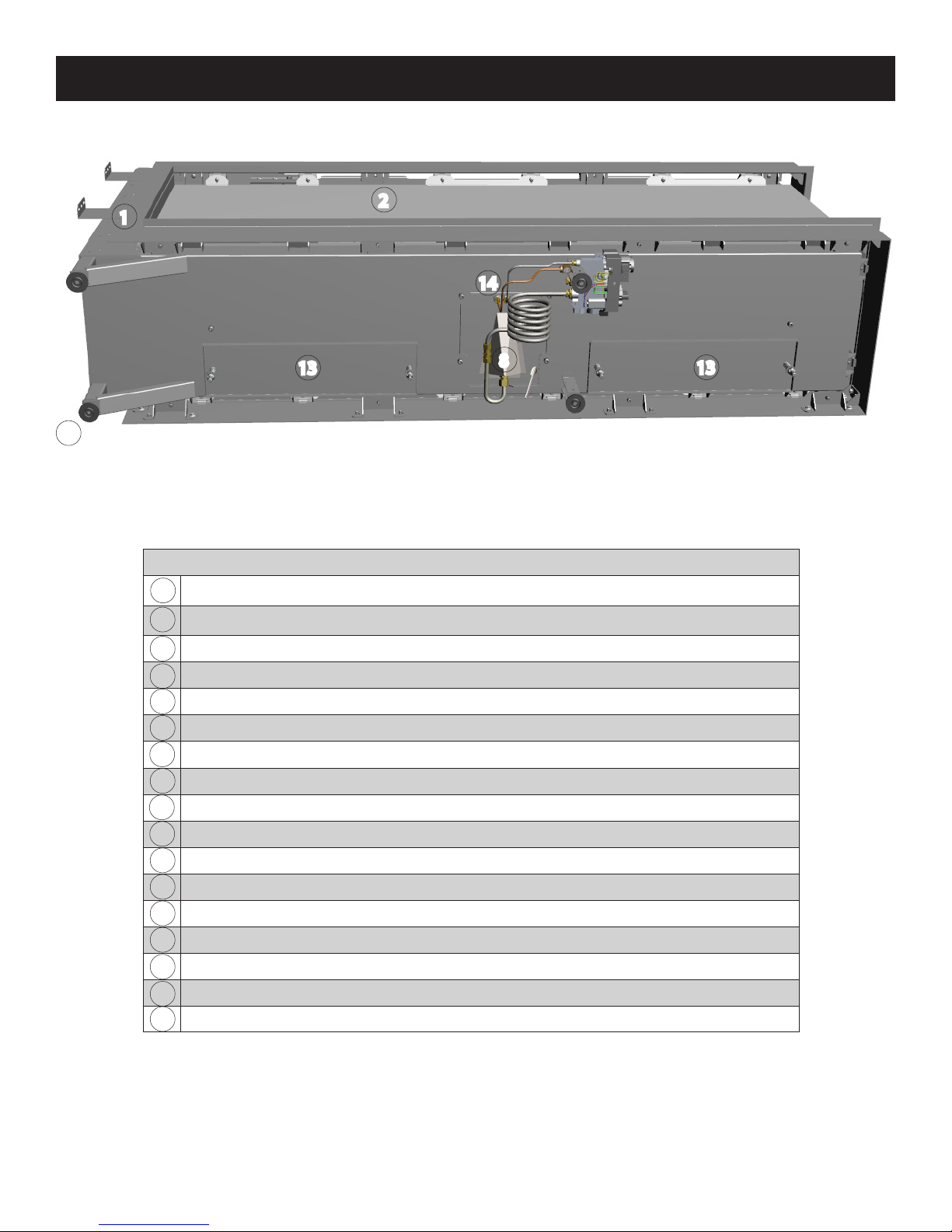
Figure 6 shows a view from below.
Table of Fireplace Parts
Outer Frame Face- surrounds the glass panels and limits the non-combustible wall board
1
Exterior Glass Panel - 3 or 2 depending on model
2
Support Feet - four adjustable feet allow the replace to be levelled
3
Hearth Panel - supports various Fire Media
4
Primary Burner - produces the ame
5
Flange
6
Pilot Burner - the part of the safety circuit which lights the Main Burner
7
2nd Thermocouple - the part of the safety circuit which monitors the Main Burner
8
Finish Trim - hides the Glass Clamps
9
Interior Glass Panel (N/A)
10
Glass Clamp - holds the Glass Panel in place (16 ea. - L140 T, 18 ea. - L140 RD, 1/3, 2/3)
11
Vent Collar - accepts the 5” x 8” venting adapter (included)
12
Relief Door - part of the safety system. Do NOT block the operation.
13
Pilot Assembly
14
Upright Trim - (4 ea. - L140 T, 2 ea. - L140 RD, 1/3, 2/3 hides the vertical Glass Clamps)
15
No material zone
16
Top of replace
17
Element4 Gas Fireplaces EuropeanHome.com
Table 1
14
Page 15

CLEARANCES
The Lucius 140 replaces require non- combustible framing. These
are NOT zero-clearance replaces. All clearances to combustible
AND non-combustible materials MUST be maintained as described
in this manual.
LOCATING THE FIREPLACE
When selecting a location for the replace:
• Ensure that all minimum clearances to combustible AND noncombustible materials are met.
• Provide adequate clearances for servicing.
• Consider venting dimensions (rise, run and number of
elbows, etc.) when selecting the location for your replace.
• Locate the appliance out of trac and away from furniture
and draperies.
• Keep the location free of electrical, plumbing or other
heating/air conditioning ducting.
PLACING THE FIREPLACE
The base upon which the appliance rests must be sturdy, level
and built to safely support at least 500 pounds/230 kilograms.
The base may be the oor or a purpose built raised platform (e.g.
wood,metal). The base upon which the replace is installed must
have a 25 in.2/161 cm2 opening centered in it to allow the free ow
of air to the replace above unless placed on a oor. See below
MINIMUM CLEARANCE TO COMBUSTIBLES
• The appliance is approved with a minimum clearance to
combustible materials of 26”/660 mm to the top, 11”/2 80
mm on all sides and 4”/100 mm to the bottom. Any spacer
or framing used closer than this dimension must be noncombustible (e.g. metal).
• The minimum clearance to non-combustible material is
2”/5 0 mm. (See Figures 7 - 18, clearance shown in red)
• The minimum distance from the bottom of the appliance to
the room ceiling is 72”/1830 mm. (See Figure 21, Table 2)
• When installing the venting the following clearances to
combustible materials MUST be maintained:
a. 3”/76 mm above any horizontal venting
b. 1”/25 mm to venting sides or below any horizontal
venting
• Non-combustible materials may be installed to a zero
clearance, to the outer faces of the appliance outer frame.
However, they must not cover (or prevent the removal of)
the glass panels or the control equipment.
• Do not block or restrict the convection gap between the
appliance rebox and the appliance outer frame (top of
glass panels).
The feet on the appliance are designed to sit on a at platform,
however the appliance must not be installed on any combustible
material other than wood. For example, carpet or linoleum bases
are not permitted.
Do not place anything between the bottom of the rebox and
the bottom of the feet. Ensure that the lineset (which includes the
gas valve, electrical wiring, and gas lines) does not impede the full
operation of the relief doors.
The minimum clearances (air spaces) to combustible materials
must be maintained. It is of the greatest importance that the
replace and vent system be installed only in accordance with
these instructions.
Clearance to combustibles summary:
Back: 11”/280 mm
Sides: 11”/280 mm
Top: 26”/660 mm
Floor: 4”/100 mm
The Floor dimension (above) is measured from the bottom of the
rebox. This allows the feet to sit on the oor giving adequate
clearance in their lowest position.
Element4 Gas Fireplaces EuropeanHome.com
15
Page 16
11”
280 mm
11”
280 mm
CLEARANCES
Lucius 140 Room DiviDeR
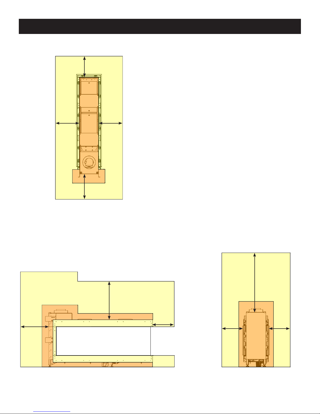
Figures 7* through 9* show (in yellow) the clearances to
combustible material which must be maintained.
No material of any kind is allowed between the
11”
280 mm
bottom of the support feet and the bottom of the
rebox (shown in red).
No material of any kind is allowed within 2”/50 mm
from the top of the replace (shown in red).
No material of any kind is allowed within 2”/50 mm
from the metal sides the replace (shown in red).
Facing material should be installed against the outer
frame of the replace, with an 1/8” vertical clearance
to allow for heat expansion.
LUCIUS 140
11”
280 mm
11”
280 mm
Figure 7 Plan View - Lucius 140 Room Divider
26”
660 mm
11”
280 mm
*drawings not to scale
280 mm
11”
26”
660 mm
11”
280 mm
Figure 8 Front Elevation View - Lucius 140 Room Divider Figure 9 Side Elevation View - Lucius 140 Room Divider
Element4 Gas Fireplaces EuropeanHome.com
16
Page 17
11”
280 mm
11”
280 mm
11”
280 mm
CLEARANCES
Lucius 140 TunneL
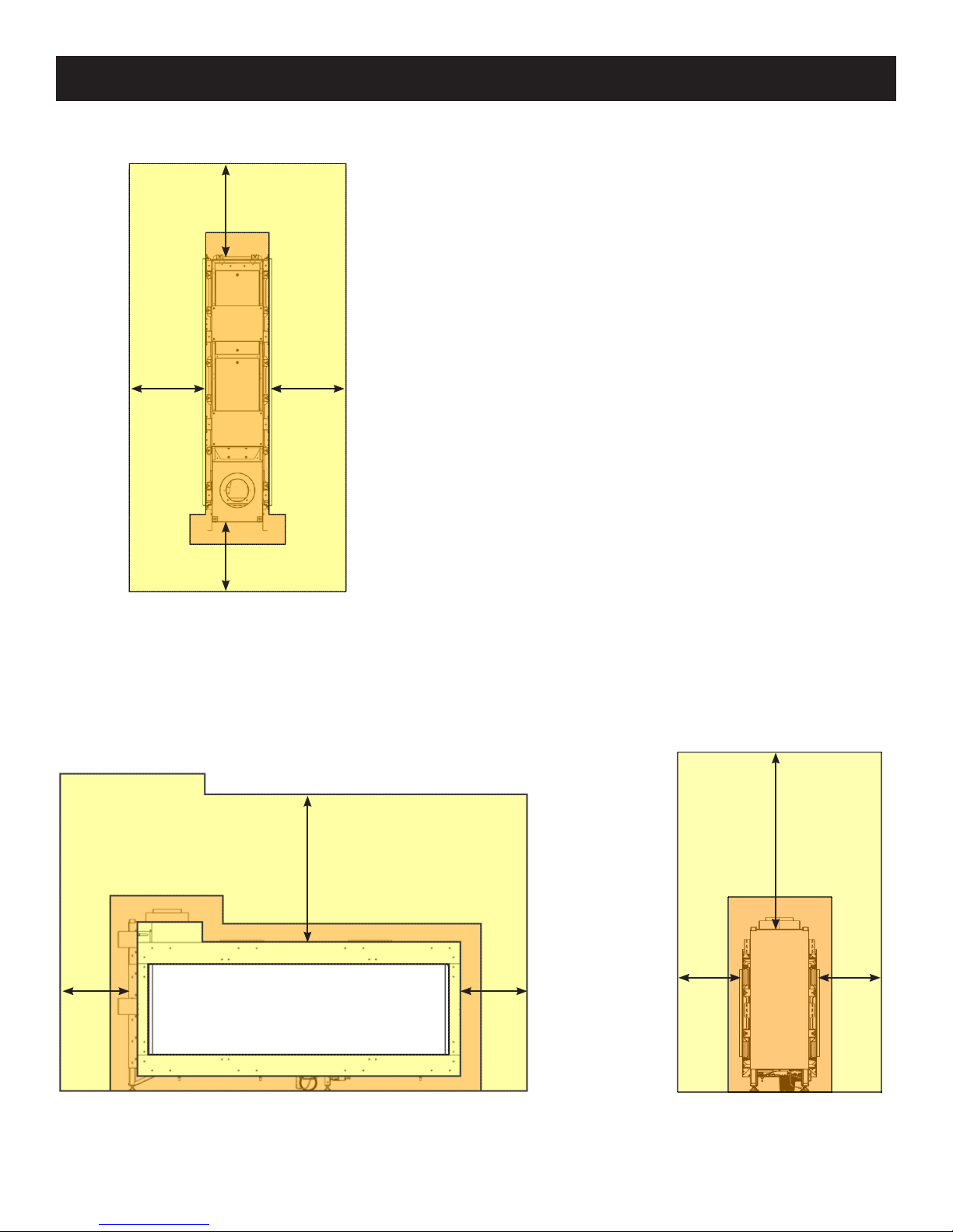
Figures 10* through 12* show (in yellow) the clearances
to combustible material which must be maintained.
No material of any kind is allowed between the
bottom of the support feet and the bottom of the
rebox (shown in red).
No material of any kind is allowed within 2”/50 mm
from the top of the replace (shown in red).
No material of any kind is allowed within 2”/50 mm
from the metal sides the replace (shown in red).
Facing material should be installed against the outer
frame of the replace, with an 1/8” vertical clearance
to allow for heat expansion.
LUCIUS 140 TUNNEL
11”
280 mm
Figure 10 Plan View - Lucius 140 Tunnel
11”
280 mm
26”
660 mm
11”
280 mm
*drawings not to scale
11”
280 mm
26”
660 mm
11”
280 mm
Fig ur e 11 Front Elevation View - Lucius 140 Tunnel Fi gure 12 Side Elevation View - Lucius 140 Tunnel
Element4 Gas Fireplaces EuropeanHome.com
17
Page 18
11”
280 mm
11”
280 mm
11”
280 mm
CLEARANCES
Lucius 140 1/3
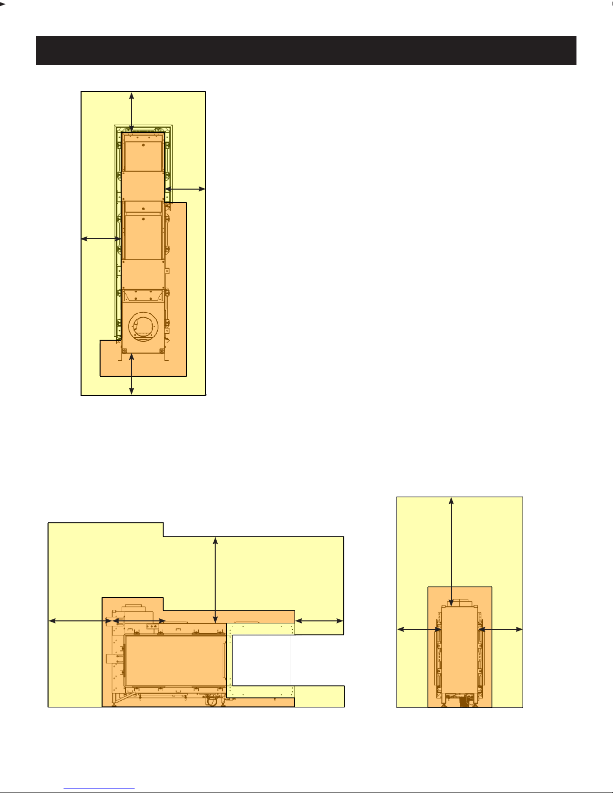
Figures 13* through 15* show (in yellow) the clearances
to combustible material which must be maintained.
No material of any kind is allowed between the
bottom of the support feet and the bottom of the
rebox (shown in red).
No material of any kind is allowed within 2”/50 mm
from the top of the replace (shown in red).
No material of any kind is allowed within 2”/50 mm
from the metal sides the replace (shown in red).
Facing material should be installed against the outer
frame of the replace, with an 1/8” vertical clearance
to allow for heat expansion.
LUCIUS 140 1/3
11”
280 mm
Figure 13 Plan View - Lucius 140 1/3
11”
280 mm
26”
660 mm
11”
280 mm
*drawings not to scale
11”
280 mm
26”
660 mm
11”
280 mm
Figure 14 Front Elevation View - Lucius 140 1/3 Figure 15 Side Elevation View - Lucius 140 1/3
Element4 Gas Fireplaces EuropeanHome.com
18
Page 19
11”
280 mm
11”
280 mm
11”
280 mm
CLEARANCES
Lucius 140 2/3
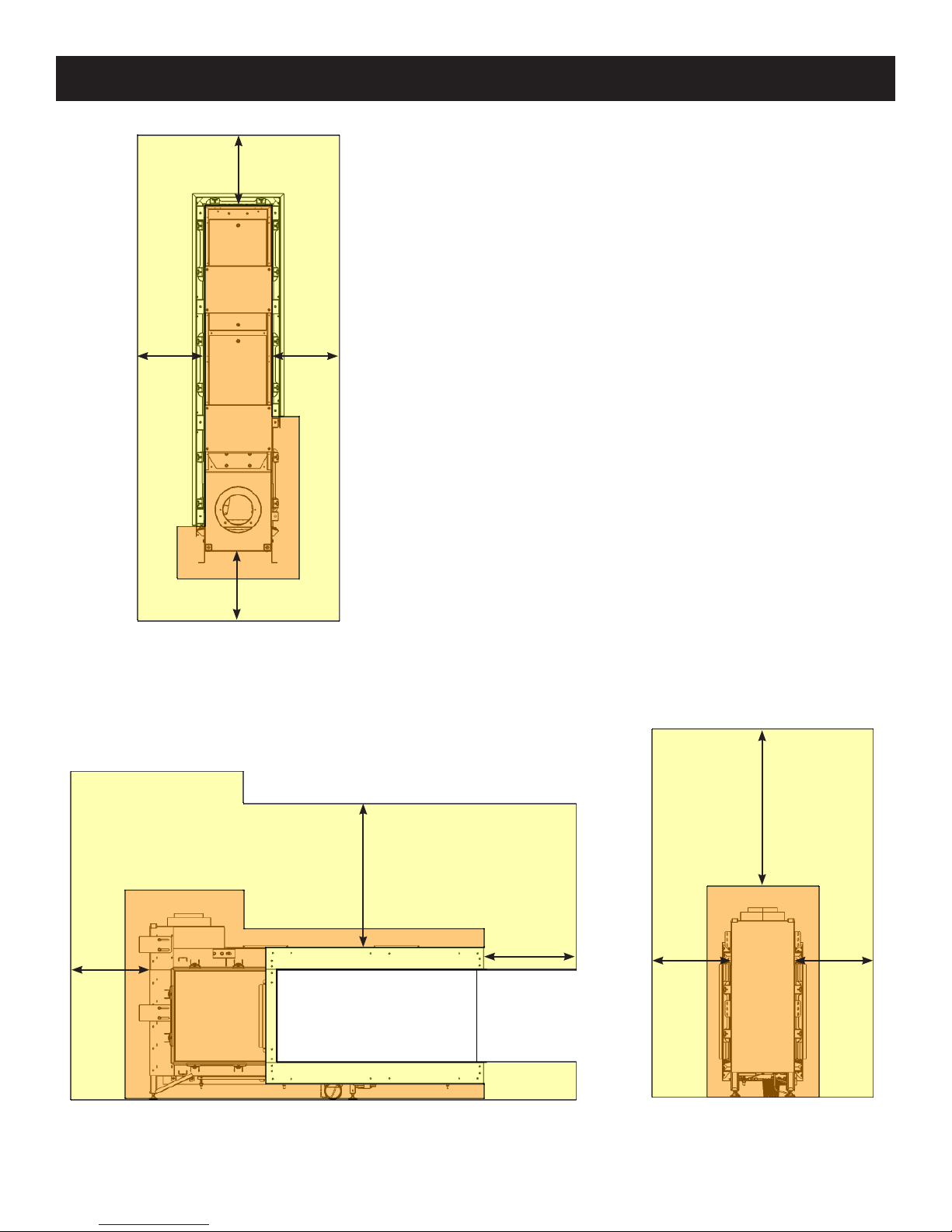
Figures 16* through 18* show (in yellow) the clearances
to combustible material which must be maintained.
No material of any kind is allowed between the
bottom of the support feet and the bottom of the
rebox (shown in red).
No material of any kind is allowed within 2”/50 mm
from the top of the replace (shown in red).
No material of any kind is allowed within 2”/50 mm
from the metal sides the replace (shown in red).
Facing material should be installed against the outer
frame of the replace, with an 1/8” vertical clearance
to allow for heat expansion.
LUCIUS 140 2/3
11”
280 mm
11”
280 mm
Figure 16 Plan View - Lucius 140 2/3
26”
660 mm
*drawings not to scale
11”
280 mm
11”
280 mm
26”
660 mm
11”
280 mm
Fi gure 17 Front Elevation View - Lucius 140 2/3 Figure 18 Side Elevation View - Lucius 140 2/3
Element4 Gas Fireplaces EuropeanHome.com
19
Page 20
CLEARANCES
(2") 50
C
SECTION
A-A
900
COMBUSTIBLE MATERIALS
NOT PERMITTED IN FRONT
OF GLASS
(2) 50
MANTELS
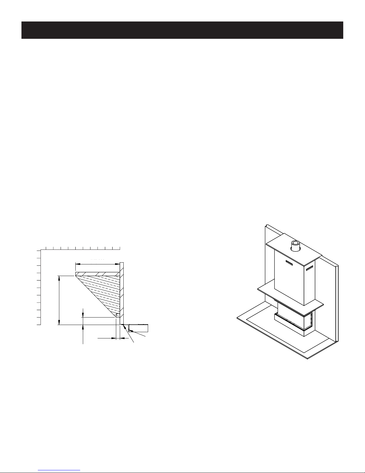
The graph in Figure 19 shows a range of allowable depths and heights for a combustible mantel installation.
As shown, the minimum allowable mantel height above the replace opening is 2”/50 mm with a 1”/25 mm deep mantel.
The maximum mantel depth is 12”/300 mm at a minimum height above the replace opening of 13”/330 mm.
All of the mantel height/depth combinations fall in between these extremes in accordance with Figure 19.
Mantels made of non-combustible material are allowed inside these dimensions but they will be subjected to elevated
temperatures and may become too hot to touch.
A typical completed installation with mantel is shown in Figure 20.
INCHES
20
18
16
14
12
10
8
6
4
2
0
(13) 330
Mantel Height
13”/330 mm
Mantel Height
Mantel Depth
Mantel Depth
(12) 300
12”/300 mm
(1) 25
1”/25 mm
2”/50 mm
Figure 19
2468101214161820
0
GLASS
TOP OF
FIREPLACE
OPENING
Figure 20
Element4 Gas Fireplaces EuropeanHome.com
20
Page 21
CLEARANCES
TYPICAL CLEARANCE DIAGRAMS
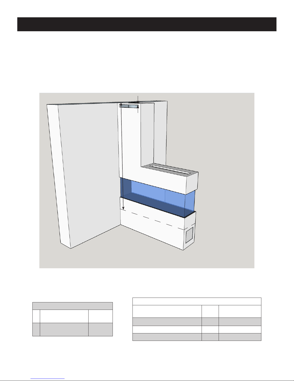
The total area of the convection air outlet(s) depends on the replace model. The location of the outlet(s) must allow for the free
movement of air and must not allow excessive convection air to build up within the chase. The top of the outlet(s) must be at least
1”/25 mm down from the ceiling and we recommend no more than 3”/76 mm down. The minimum distance from the bottom of the
appliance to the room ceiling is 72”/1830 mm.
Convection
Air Outlet
B
A
Minimum Distances
Room ceiling to
A
appliance bottom
Room ceiling to top of
B
Convection Air Outlet1”25 mm
72”
1830 mm
Table 2
Element4 Gas Fireplaces EuropeanHome.com
Figure 21
Convection Air Outlet Area by Model
Model
Square
Inches
Square Centimeters
Lucius 140 Room Divider 119 768
Lucius 140 Tunnel 112 722
Lucius 140 1/3, Lucius 140 2/3 77 497
Table 3
21
Page 22
GAS and ELECTRIC
INSTALLING THE GAS LINE
Correctly size and route the gas supply line from the supply regulator to the area where the appliance is to be installed as per
requirements outlined in the latest edition of the National Fuel Gas Code, NFPA 54 (USA) or CAN/CSA-B149.1 (Canada).
Never use galvanized or plastic pipe unless specied for use with gas. Refer to the table below for proper sizing of the supply gas
line. Gas lines must be routed, constructed and made of materials that are in strict accordance with local codes and regulations. A
qualied plumber or gas tter should be hired to correctly size and route the gas supply line to the appliance.
Installing a gas supply line from the fuel supply to the appliance involves numerous considerations of materials, protection, sizing,
locations, controls, pressure, sediment trap, and other criteria. The sizing and/or installing of gas piping should only be performed
by a qualied plumber or gastter.
The gas control inlet accepts a ⁄” NPT tting.
This replace arrives from the factory for use with natural gas. See Appendix Three for LP (propane) conversion instructions.
Schedule 40 Black Iron Pipe
Length (feet) Inside Diameter (Inches)
0 - 10 ½ ⁄
10 - 40 ½ ½
40 - 100 ½ ½
100 - 150 ¾ ½
150 - 200 ¾ ½
Natural
Gas
Table 4
Propane
Gas
ELECTRICAL REQUIREMENTS
The Element4 replaces use a receiver and remote control for their burner operation. The remote control comes with (3) AAA
batteries and the receiver is powered by a 120V AC adapter, included.
The installer must provide an approved 120V AC wall receptacle to be placed within the six foot cord limit of the AC adapter.
The receiver may be powered by either the AC adapter or (4) AA batteries - not both. Batteries do not provide an electrical backup
for the AC adapter. Using batteries in combination with the AC adapter can damage the receiver.
WARNING
Element4 Gas Fireplaces EuropeanHome.com
Electrical work must be performed by a qualied, licensed electrician.
All wiring shall be in compliance with all local, city, and state codes.
22
Page 23

VENTING
CONFIGURING THE VENTING
The replaces in this manual are direct vent replaces that use a co-axial or “pipe within a pipe” venting system. The outer “pipe” or vent
conducts fresh, outside air into the replace and the inner vent carries the exhaust outside. This system, which can run either horizontally
through a side wall or vertically through the roof, produces an ecient system because conditioned building air is not used for combustion.
All of the following points apply to every installation:
• The maximum allowable rise is 36’/11.0 m and the maximum allowable run is 9’10”/3.0 m but not in combination.
• The minimum vent conguration is a 19”/0.5 m vertical rise to a 90° elbow plus a 19”/0.5 m horizontal run to a wall termination.
• Only the 5” x 8” direct vent components from M&G DuraVent are approved for use with these replaces. Any of the M&G
DuraVent 5” x 8” direct vent components suitable for the local condition are permitted. Please visit www.europeanhome.com/
qr-support or via the QR code below for installation instructions.
• This replace is shipped with a North American venting adapter. It MUST attach to the vent collar of the replace.
• All venting measurements are taken from the top center of the vent collar on the top of the replace and all congurations
must fall within the acceptable range of the venting charts.
• When using wall terminations no more than three vertically-oriented 45° or 90° elbows are permitted. See the HORIZONTAL
TERMINATIONS section.
• When using vertical terminations no more than four 90° elbows OR eight 45° elbows OR a combination totaling no more than
360 ‘elbow degrees’. For example, a combination of two 90° elbows and two 45° elbows is allowed (90° + 90° + 45°+ 45° equals
270°) but a combination of three 90° elbows and three 45° elbows is not allowed (the total equals 405°.) These elbows can be
installed either horizontally or vertically.
• A minimum clearance of 3”/75 mm must be maintained between combustible materials and the top of any horizontal vent
pipe surface; a minimum clearance of 1”/25 mm must be maintained between combustible materials and any other vent pipe
surface.
• The horizontal parts of the venting must be pitched up, away from the replace. For every 12” / 305 mm of horizontal run, the
venting must rise ¼” ⁄ 6.5 mm toward the termination. The venting must never run downward unless with the use of a power
vent.
• Whenever venting passes through a wall, an approved heat shield or ‘wall thimble’ must be installed.
• A power vent system is available and must be used for any venting conguration which is outside of the vent graphs.
For the M&G venting installation guide or power venting installation manuals
please visit the link below.
Element4 Gas Fireplaces EuropeanHome.com
23
Page 24
VENTING
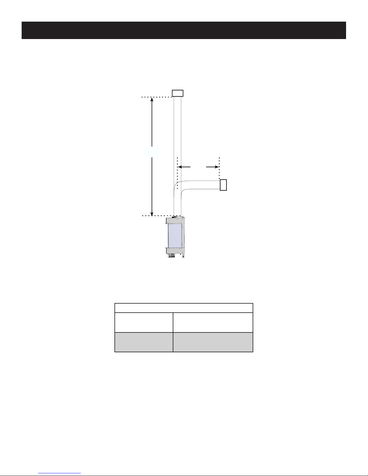
rise
run
Figure 22
APPROVED MANUFACTURERS and COMPONENTS
Manufacturer Components
M&G DuraVent, Inc.*
only DirectVent Pro®
5” x 8” venting components
Table 5
Element4 Gas Fireplaces EuropeanHome.com
24
Page 25

V
Distance “H” = 0.5-5m (min - max)
Distance “V” = 0.5-3m (min - max)
Note - for E4-10 & 11 Elbow can go
on to fire, thus “V” min = 200mm
Note2 - For E4-5, use a 50mm flue
HORIZONTAL TERMINATIONS
VENTING
H
HORIZONTAL
Restrictor
Figure 23
Dimension “H” (run) can vary between 19”/500 mm minimum to 9’10”/3.0 m maximum depending on Dimension “V”. (See Graph 1)
Dimension “V” (rise) can vary between 19”/500 mm minimum to 11’5”/3.5 m maximum depending on Dimension “H”. (See Graph 1)
Note: Congurations with horizontal terminations may need a restrictor. See the INSTALLING A RESTRICTOR section.
Element4 Gas Fireplaces EuropeanHome.com
25
Page 26
HORIZONTAL TERMINATIONS
VENTING
HORIZONTAL
Graph 1 Horizontal Termination Graph
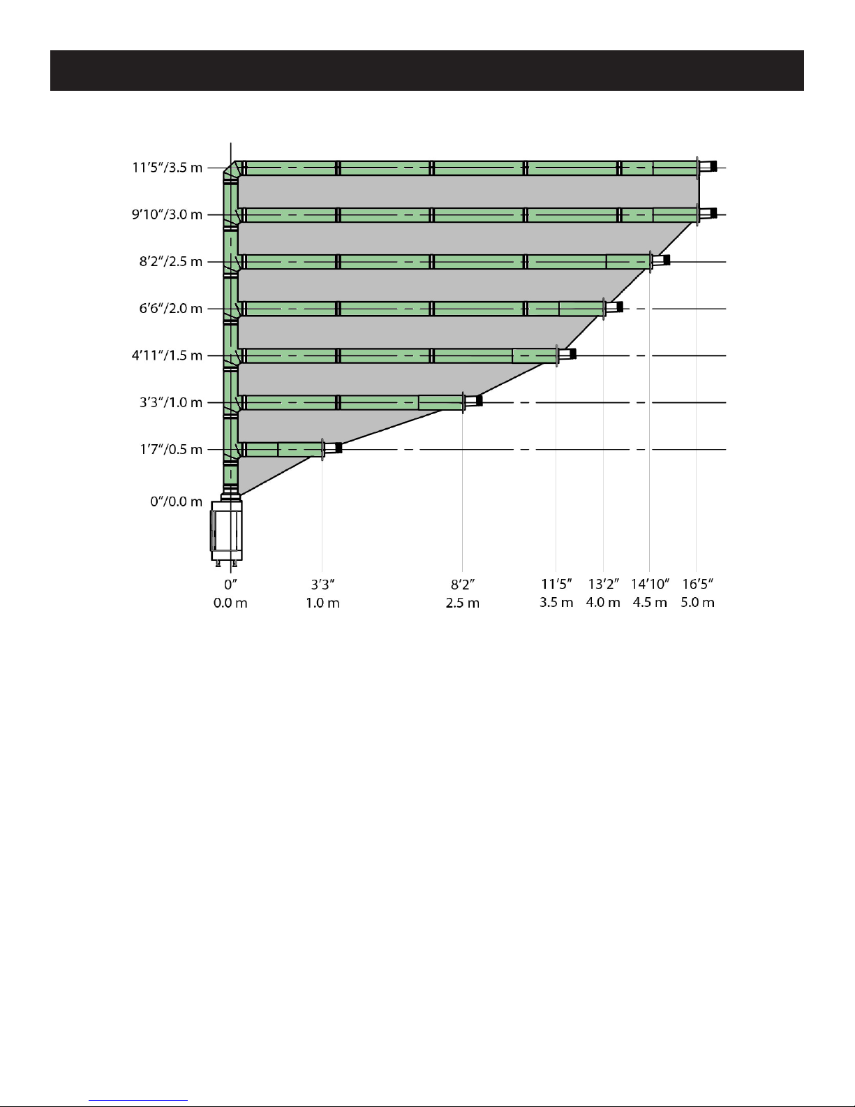
Graph 1 shows the maximum horizontal vent run (to the outside wall) for the corresponding vertical vent rise. The allowable
venting conguration MUST be within the shaded area. A power vent system is available for congurations which are not allowed
by these requirements.
• When using a wall-mounted termination, a maximum of 3 elbows (45° or 90°) may be used.
• For each second or third elbow:
- 20 ”/50 0 mm must be subtracted from the horizontal length allowance when using a 45° elbow
- 40”/1000 mm must be subtracted from the horizontal length allowance when using a 90° elbow
Example A: With a total rise of 6’6”/2.0 m and one horizontal 90° elbow, a total run of 13’2”/4.0 m is allowed.
Example B: If the rise is 8’2”/2.5 m then the run can be no longer than 14’10”/4.5 m.
Example C: If the run is 16’5”/5.0 m then the rise must be at least 9’10”/3.0 m.
Element4 Gas Fireplaces EuropeanHome.com
26
Page 27
VENTING
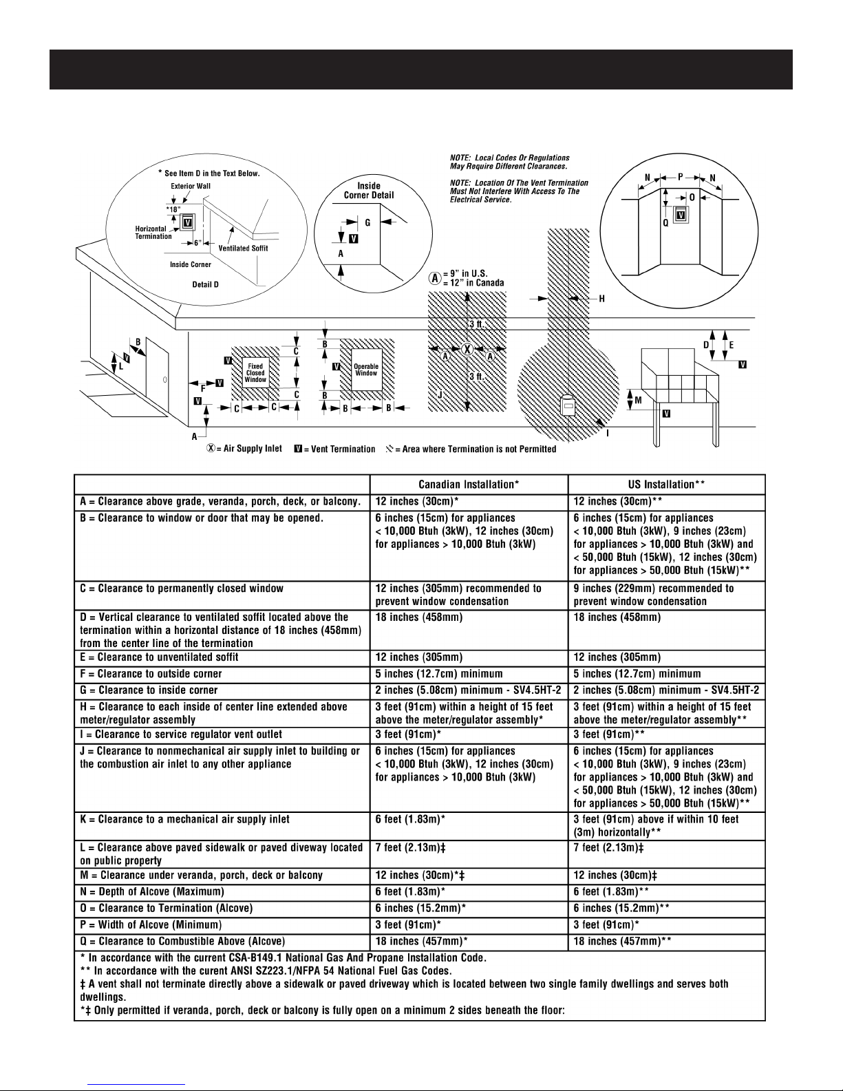
HORIZONTAL VENT TERMINATION CLEARANCES AND REQUIREMENTS
HORIZONTAL
Element4 Gas Fireplaces EuropeanHome.com
27
Page 28
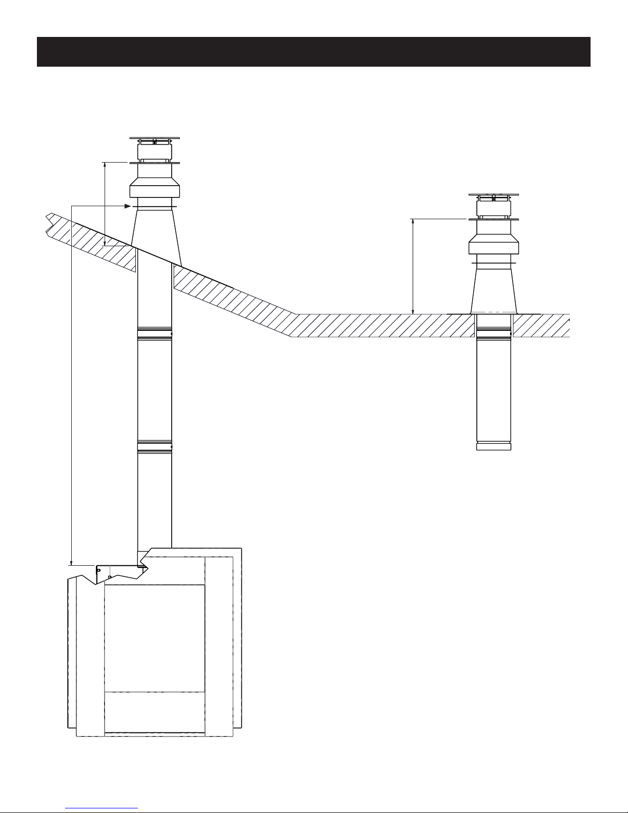
VERTICAL TERMINATIONS
minimum
12”/304 mm
150 min
VENTING
minimum
150 min
12”/304 mm
VERTICAL
V
When installing vertical venting with no elbows, dimension “V” must be at
least 36”/1.0 m minimum and no more than 36’/11.0 m maximum.
A minimum distance of 12”/304 mm between the roof and the lowest
discharge opening in the termination must be maintained.
Power vent systems are available for congurations beyond these limits.
Distance "V" 1m - 11m (min - max)
Note: Congurations with vertical terminations may need a restrictor.
See the INSTALLING A RESTRICTOR section.
Element4 Gas Fireplaces EuropeanHome.com
Figure 24 Vertical Terminations with NO elbows
28
Page 29
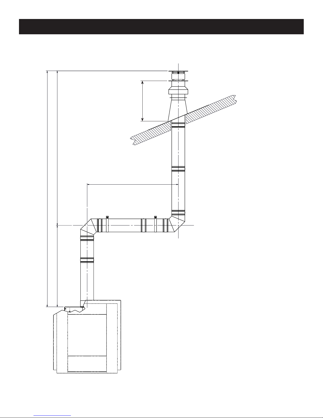
VERTICAL TERMINATIONS WITH 90° ELBOWS
minimum
12”/304 mm
V2
VENTING
VERTICAL
H
V
Distance “H” = 0”/0.0 m minimum to 9’10”/3.0 m maximum
Distance “V1” = 19”/500 mm minimum to 33’10”/10.0 m maximum
V1
Distance “V2” = 19”/500 mm minimum to 33’10”/10.0 m maximum
Distance “V” (V1+V2) = 3’3”/1.0 m minimum to 36’/11.0 m maximum
Distance “V” must be greater than twice the distance of “H”
Subtract 3’3”/1.0 m of maximum height for every 90° elbow up to a maximum
of four (4) 90° elbows.
Distance "H" = 0 - 3m (min - max)
Distance "V1" = 500mm - 10m (min - max)
Distance "V2" = 500mm - 10m (min - max)
A minimum distance of 12”/304 mm between the roof and the lowest
Distance "V" (= V1+V2) = 1m - 11m
discharge opening in the termination must be maintained.
(min - max)
Figure 25 Vertical Terminations with 90° elbows
Element4 Gas Fireplaces EuropeanHome.com
Power vent systems are available for congurations beyond these limits.
Distance "V" =2x "H" (min)
Note: Congurations with vertical terminations may need a restrictor. See the
INSTALLING A RESTRICTOR section.
29
Page 30
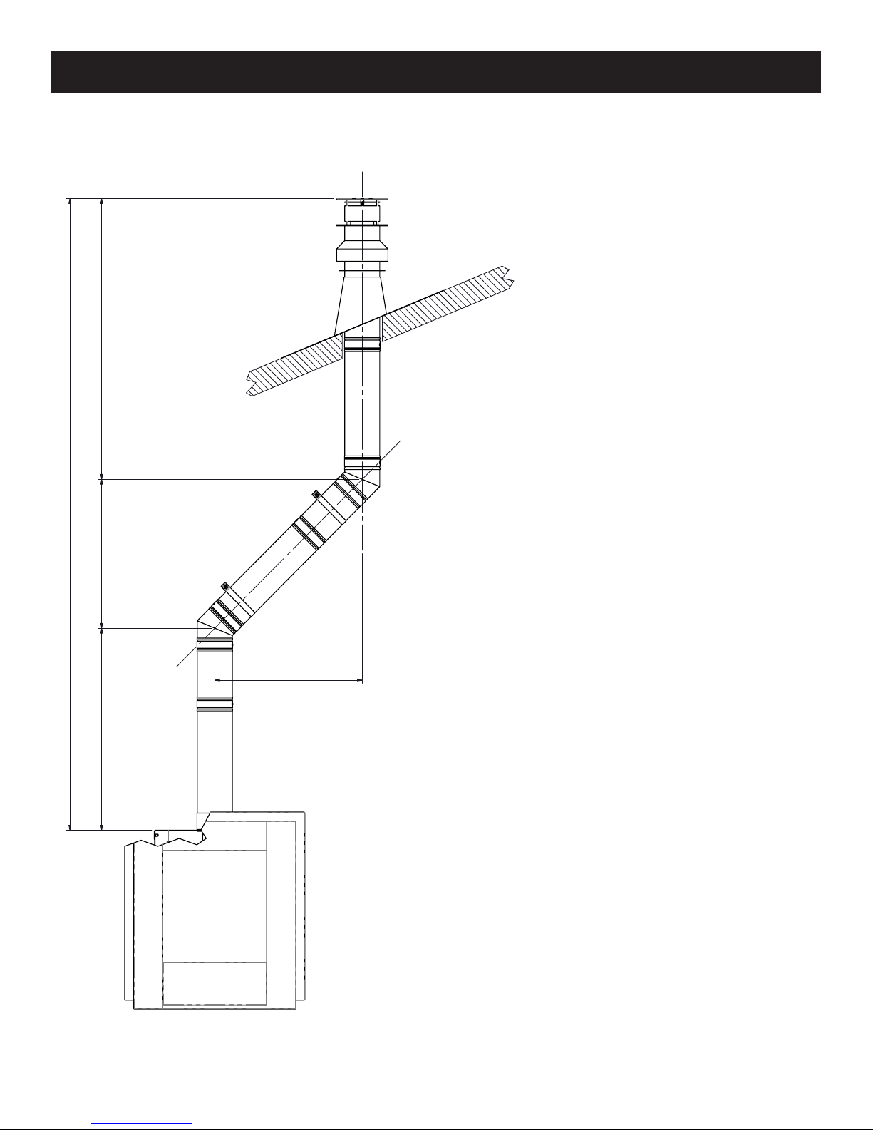
V2 V3V1
V
H
Distance "H" = 0 - 3m (min - max)
Distance "V1" = 500mm - 10m (min - max)
Distance "V2" = 200mm - 10m (min - max)
Distance "V3" = 500mm - 10m (min - max)
Distance "V" (= V1+V2+V3) = 1.2m - 11m
(min - max)
Distance "V" =2x "H" (min)
VERTICAL TERMINATIONS WITH 45° ELBOWS
VENTING
VERTICAL
Distance “H” = 0”/0.0 m minimum to 9’10”/3.0 m maximum
Distance “V1” = 19”/500 mm minimum to 33’10”/10.0 m maximum
Figure 26 Vertical Terminations with 45° elbows
Element4 Gas Fireplaces EuropeanHome.com
Distance “V2” = 8”/200 mm minimum to 33’10”/10.0 m maximum
Distance “V” (V1+V2+V3) = 3’11”/1.2 m minimum to 36’/11.0 m maximum
Distance “V” must be greater than twice the distance of “H”
Subtract 19”/500 mm of maximum height for every 45° elbow up to a maximum of
eight (8) 45° elbows.
Power vent systems are available for congurations beyond these limits.
Note: Congurations with vertical terminations may need a restrictor. See the
INSTALLING A RESTRICTOR section.
30
Page 31
VENTING
VERTICAL
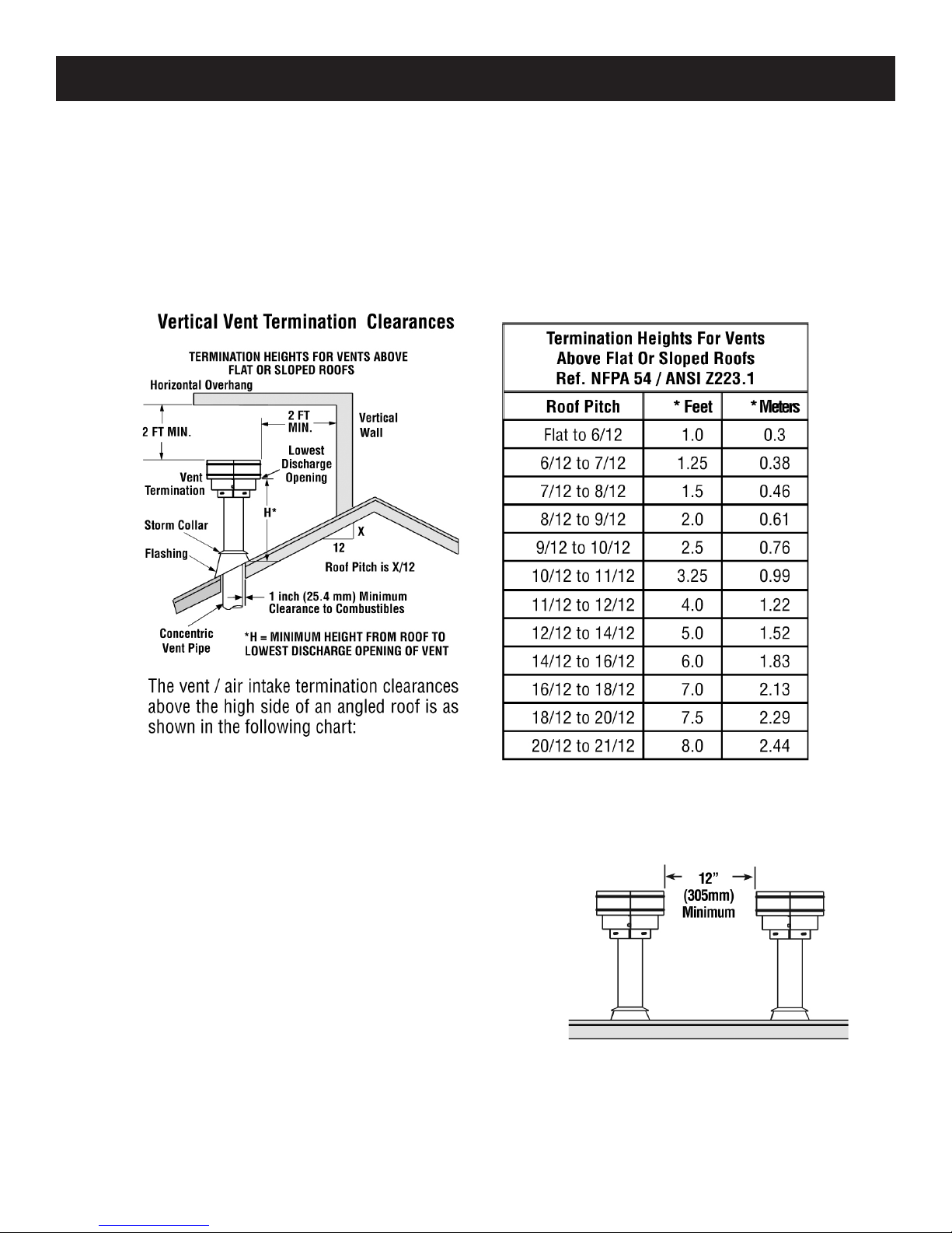
VERTICAL TERMINATION CLEARANCES AND REQUIREMENTS
Important Note for Roof Terminations
These instructions should be used as a guideline and do not supersede local codes in any way. Install venting according to local
codes, these instructions, the current National Fuel Gas Code (ANSI Z223.1 in the USA) or the current standard of CAN/CSA-B149.1
in Canada.
A second termination may be no closer than 12”/305 mm. (See Figure 27)
Element4 Gas Fireplaces EuropeanHome.com
Chart 1 Termination Heights
Figure 27 Multiple Termination Clearance
31
Page 32
VENTING
RESTRICTORS
INSTALLING A RESTRICTOR
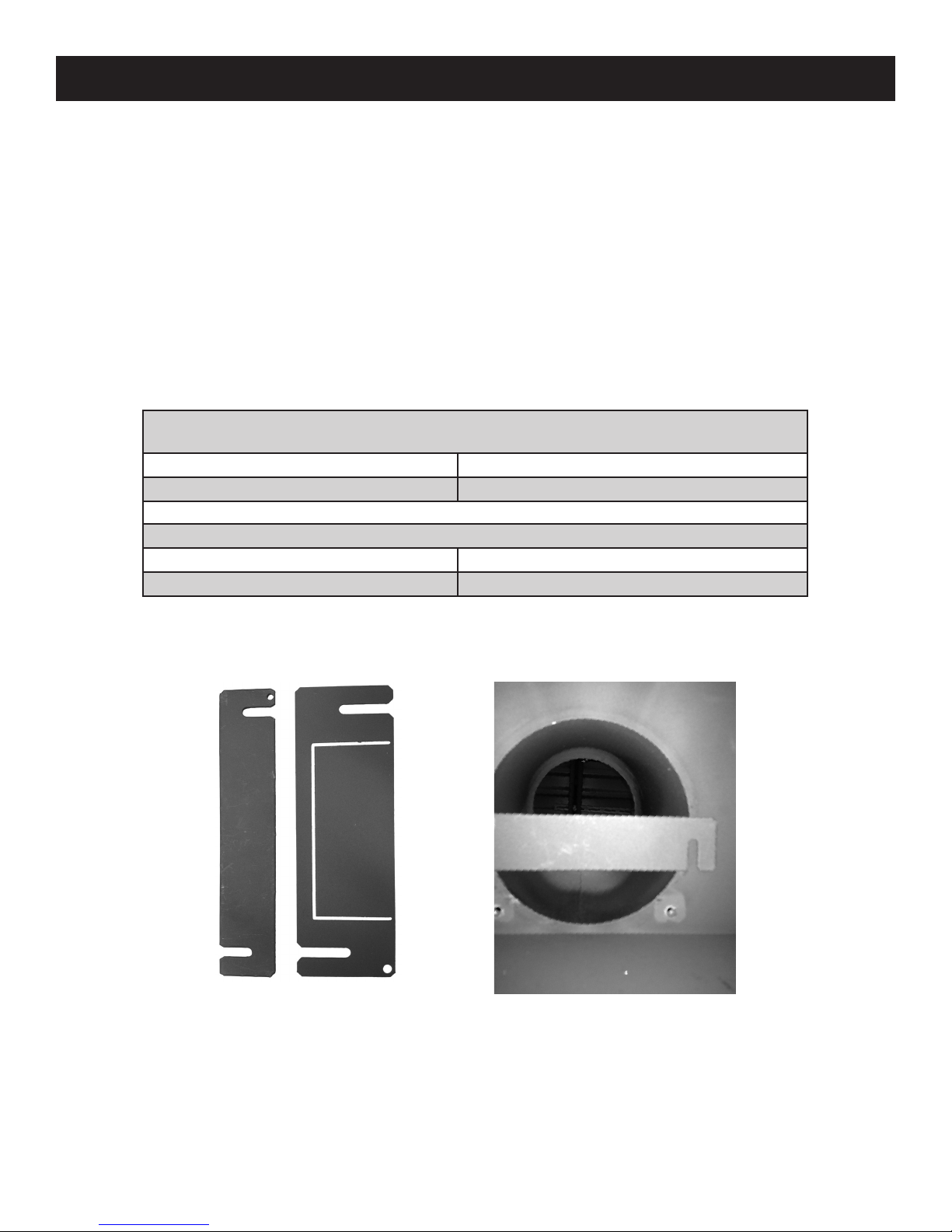
As previously noted, restrictors must be tted in some congurations. Use the table below to determine which restrictor may be
needed with your venting conguration. The restrictors are shown in Figure 28.
The restrictor for all replace models installs at the very bottom of the outlet collar. Attach the appropriate restrictor to the
bottom of the outlet collar as shown in Figure 29 using the screws provided.
When Using a Horizontal (Wall) Termination
When vertical section is up to 39½”/1 m no restrictor required
When vertical section is 39½”/1 m to 9’10”/3 m 35 mm restrictor
--------------------------------------------------------------------------------------------------------------------------------------
When Using a Vertical (Roof) Termination
When rise is up to 6’6”/2 m 35 mm
When rise is above 6’6”/2 m 60 mm
35 mm
Figure 28
Element4 Gas Fireplaces EuropeanHome.com
60 mm
Figure 29
32
Page 33
ENCLOSING the FIREPLACE
When enclosing your Element4 replace the use of non-combustible building materials is REQUIRED.
Please read and understand the following.
COMBUSTIBLE MATERIALS
Materials that can catch re and burn are considered combustible. Any material that is made of, or faced with, wood, wood pulp,
paper, plastic or any other material that can catch re and burn is considered combustible. Even though these materials may have
been 'ame-proofed', made 're-resistant' or are 're-rated' they are considered combustible. Standard and Type X drywall are both
combustible.
NON-COMBUSTIBLE MATERIALS
A given material is said to be non-combustible when it cannot catch re and burn. For example, materials made entirely, or in
combinations, of, stone, brick, concrete, tile, steel, plaster or glass are considered non-combustible.
The table below shows a list of materials which, as of this writing, are reported by their manufacturers to be non-combustible (in
accordance with the ASTM E136 standard) AND approved for use around replaces.
Skamol Skamotec® 225 and Promat PROMATECT®-L are preferred products for enclosing replaces.
Product*
Skamol Skamotec® 225 Fireplace Building Board
Promat PROMATECT®-L Insulating Boards
James Hardie Building Products HardieBacker® 500 ½” Cement Board
James Hardie Building Products HardieBacker® ¼” Cement Board
U.S. Architectural Products Versaroc® Cement Bonded Particle Board
U.S. Architectural Products Cem-Clad® Cement Panel
* The listed brand names are trademarks of their respective companies
1
Skamol Americas, Inc.
Toll Free: (844) 475-2665
E-mail: [email protected]
www.skamotec225.com
2
Promat Inc.
(865) 681- 0155
E-mail: [email protected]
www.promat.co.uk
3
James Hardie Building Products
231 S. LaSalle St., Suite 2000
Chicago, Illinois 60604
Toll Free: (888) 542-7343
www.jameshardie.com
Element4 Gas Fireplaces EuropeanHome.com
33
4
U.S. Architectural Products, Inc.
1117 Douglas Avenue, Unit 1
North Providence, Rhode Island 02904
Toll Free: (800) 243-6677
www.architecturalproducts.com
Page 34

ENCLOSING the FIREPLACE
THE ENCLOSURE
A safe installation of your Element4 replace requires that four things be clearly understood.
1. Most important, these replaces are NOT zero-clearance replaces. Unlike zero-clearance replaces, there is not a metal box
around the Element4 replaces. With no metal box there are no louvers to distract your view of the re. However, we want the
cooling advantage of a metal box so your site-built, non-combustible enclosure will substitute.
2. Your replace enclosure must be made to act the way a metal replace box acts - letting room air in below and warm
convection air out above. The framing cannot interfere with the air ow. The inlet for the room air is part of the replace and
cannot be changed or adjusted. The convection air outlet is part of your enclosure design, is provided by you and MUST be
included. Note: The Convection Air Outlet must be installed in the same room as the replace and a space which ALWAYS ows air
into the room in which the replace is installed. The ow of convection air must NOT be blocked.
3. Since these are not zero-clearance replaces, the clearances and dimensions listed in the CLEARANCES section MUST be
maintained. Only the non-combustible wall, the mounting brackets and the venting may touch the replace. As previously
stated, nothing may be built closer than 2”/50 mm to the non-glass sides.
4. The controls will be mounted to your enclosure and below the burner. The controls are at the end of a 50”/1270 mm line set
and are to be mounted to the Wall Access Door which is included. The controls must be located for ease of physical access
(gas line, maintenance, etc.) as well as wireless signal (remote control) access. See the LOCATING THE CONTROLS and the MOUNTING THE
CONTROLS sections.
The combination of multiple glass sides and no zero-clearance box makes for a non-typical enclosure project. It may seem
straightforward to build the ‘rough opening’, set the replace then attach the wall. However, for most projects, it will be easier to
rst set the replace in position then enclose it with Skamol Skamotec® or Promat PROMATECT® building board.
ONLY non-combustible framing must be used to enclose these replaces.
In all cases, the framing/wall around these replaces must NOT be supported by the replace. The enclosing walls must be attached to
another structure which can bear their entire weight and the weight of any attachments to the walls such as TVs, shelves, artwork, etc.
When installing the replace against an existing nished wall, the wall MUST BE completely covered with Skamotec 225 or Promatect
building board. All clearances between the replace and wall MUST BE maintained.
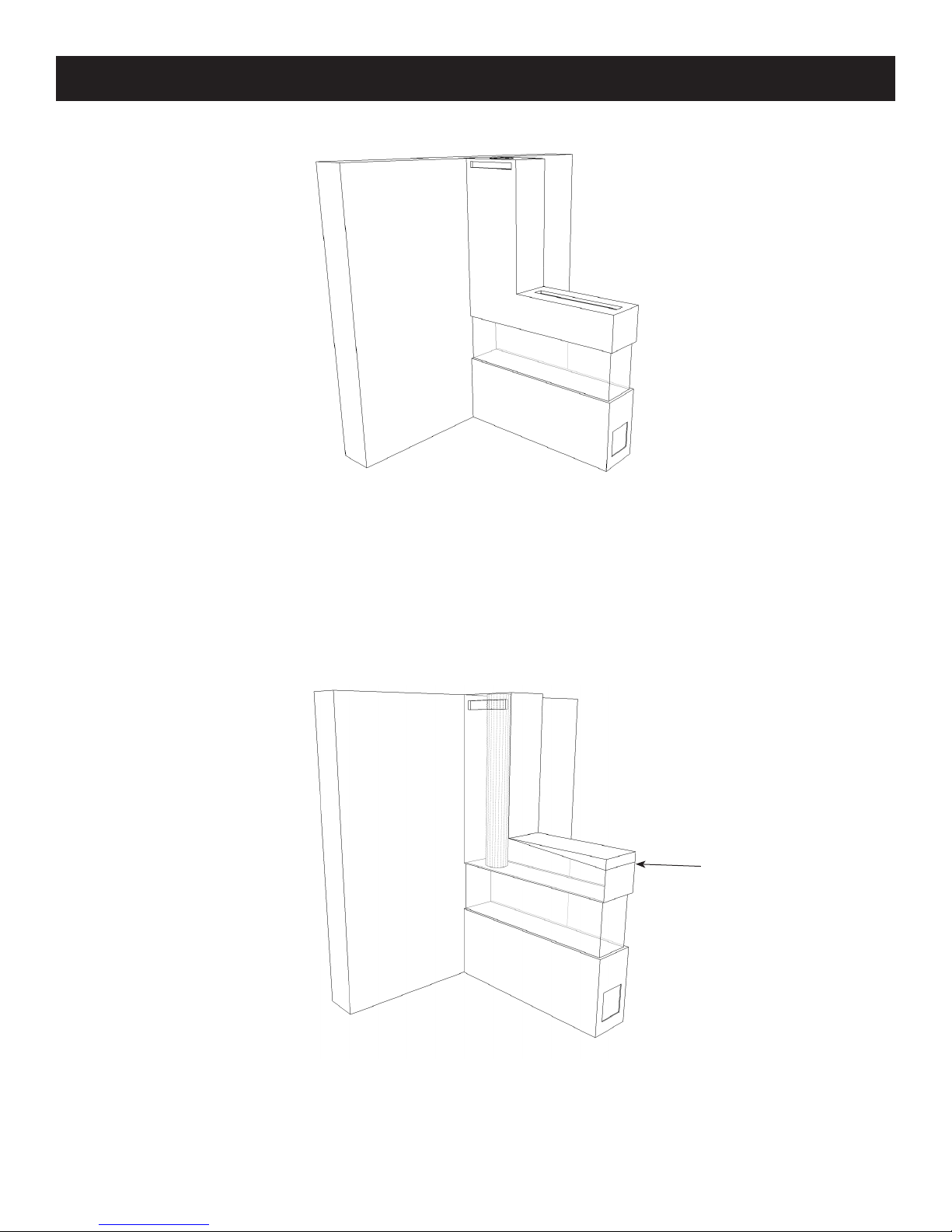
CONVECTION AIR OPENING
A convection air outlet is always required. The opening size of the convection air outlet varies by replace model. Table 3, on page
21, shows the minimum total area required for the various models in this manual. The convection air outlet may take many forms and
must always allow the free ow of warm air up through the chase and out into the room in which the replace is installed. Shown
on the next page are a number of ways to design the convection air outlet into your project.
Element4 Gas Fireplaces EuropeanHome.com
34
Page 35
ENCLOSING the FIREPLACE
Lucius with Open Top
Bae
Element4 Gas Fireplaces EuropeanHome.com
Lucius with Endwall Outlets
35
Page 36
ENCLOSING the FIREPLACE
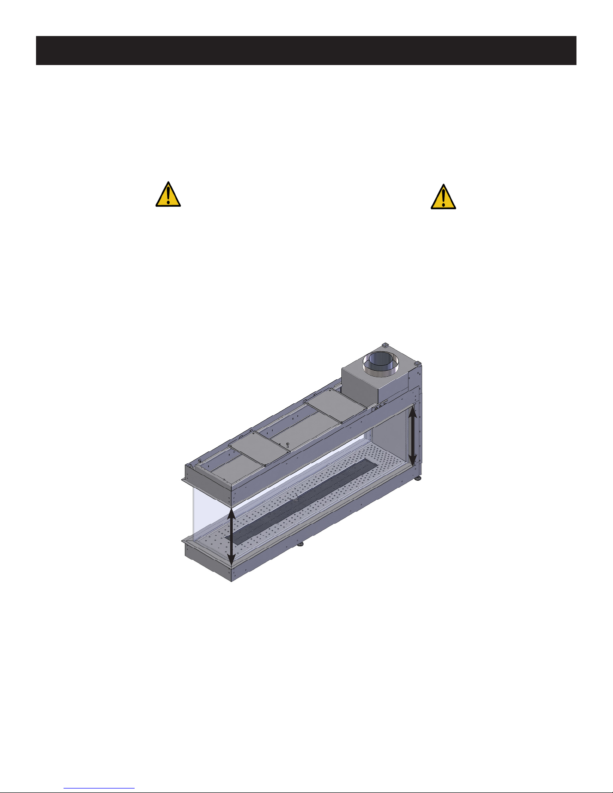
DO NOT ALLOW THE FIREPLACE
TO BEAR ANY WEIGHT
Dimension A and Dimension B (see below) must be equal throughout the installation.
Any support framing must be at least 2”/50 mm (NON-combustible framing ONLY)
above and beside the replace. The entire weight of the non-combustible walls must
be borne by a structure other than the replace.
Dimension A
Dimension B
Figure 30
Element4 Gas Fireplaces EuropeanHome.com
36
Page 37
ENCLOSING the FIREPLACE
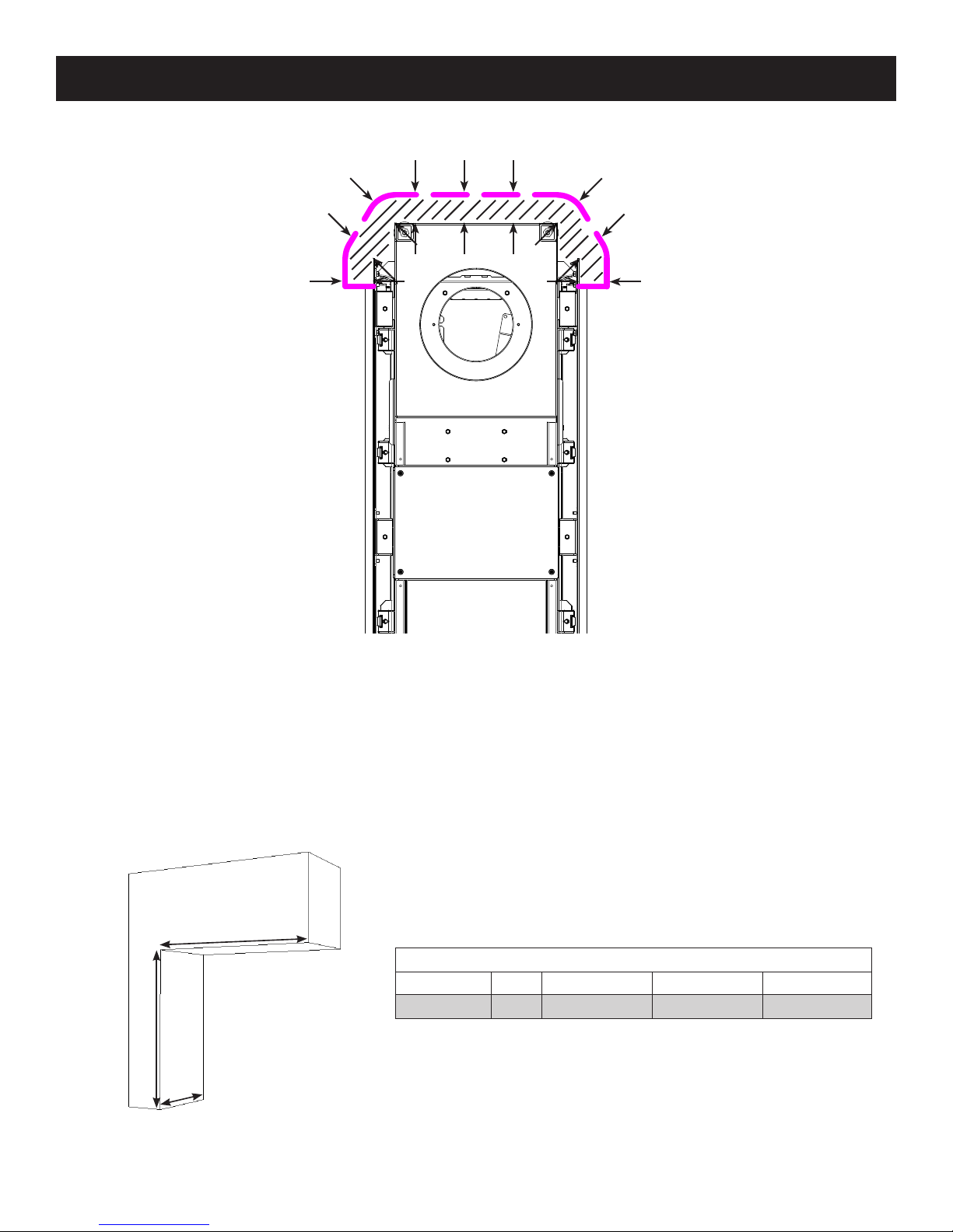
2”/50 mm
2”/50 mm 2”/50 mm
Xc
Z
Yc
Figure 31
Element4 Gas Fireplaces EuropeanHome.com
Rough Opening Dimensions for NON-COMBUSTIBLE Framing
Model Figure K L M
Lucius 140 R 31 18⁄”/464 mm 62¼”/1582 mm 39½”/1002 mm
Table 6
37
Page 38
ENCLOSING the FIREPLACE
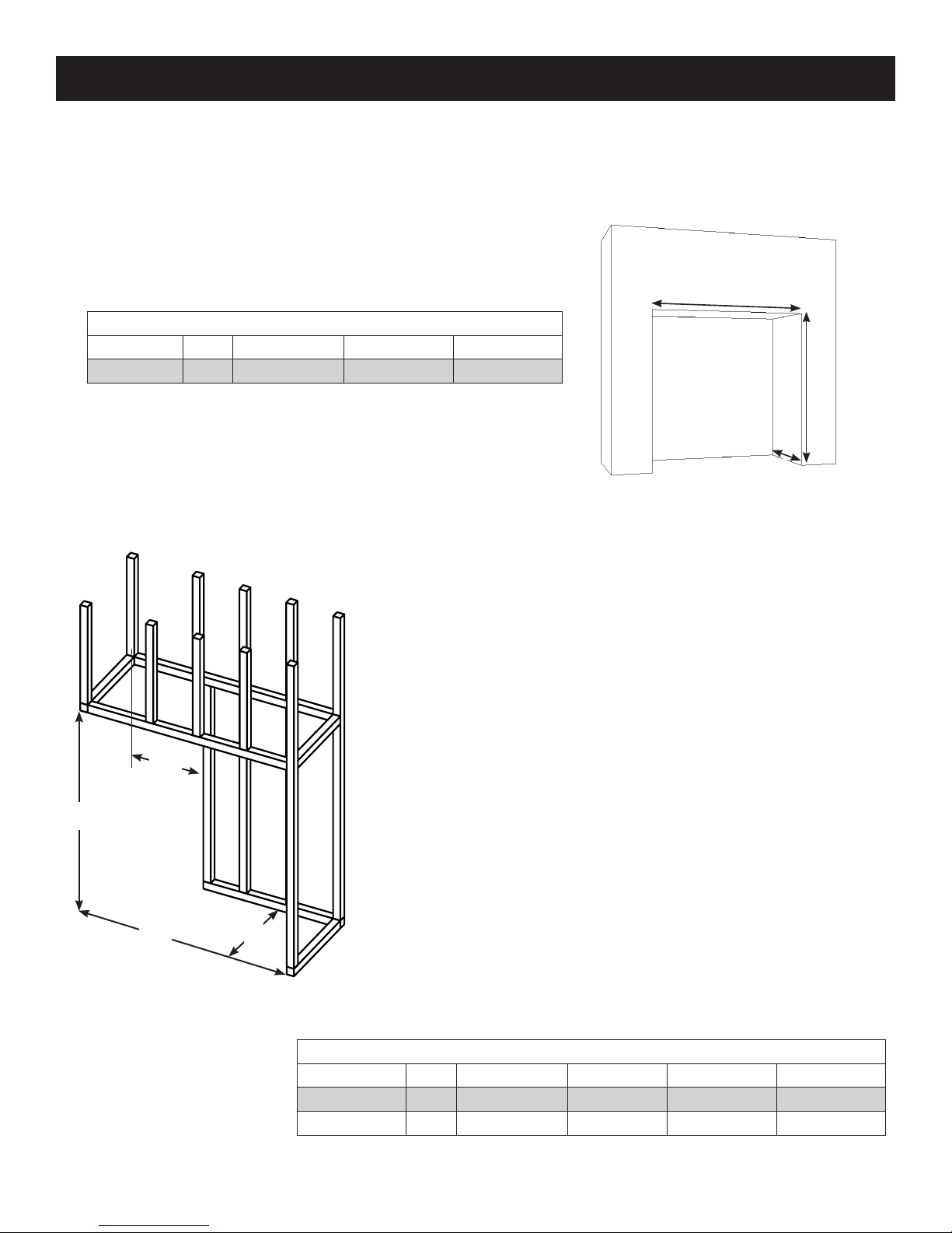
Rough Opening Dimensions for NON-COMBUSTIBLE Framing
Model Figure Xc Yc Z
Lucius 140 T 32 65”/1652 mm 14⁄”/364 mm 39½”/1002 mm
Table 7
Xc
Z
Yc
Figure 32
H
J
G
Figure 33
Element4 Gas Fireplaces EuropeanHome.com
I
Rough Opening Dimensions for NON-COMBUSTIBLE Framing
Model Figure G H I J
Lucius 140 1/3 33 62¼”/1582 mm 20½”/519 mm 18⁄”/464 mm 39½”/1002 mm
Lucius 140 2/3 33 62¼”/1582 mm 37½”/949 mm 18⁄”/464 mm 39½”/1002 mm
Table 8
38
Page 39

ENCLOSING the FIREPLACE
COLD CLIMATE INSULATION
For cold climate installations, it is especially important to insulate outside the chase cavity, between studs and under the oor on
which appliance rests, if oor is above ground level. Gas line holes and other openings should be lled with approved restop.
If the replace is being installed on a cement slab in cold climates, a sheet of plywood or a raised platform can be placed underneath
to prevent cold transferring to the replace and into the room. It also helps to tape the venting for maximum air tightness and to
caulk restops.
LOCATING THE CONTROLS
The control system for the Element4 replaces consist of three major components: the receiver, the transmitter and the gas valve.
The transmitter is the remote control by which you operate the replace. The receiver and the gas valve are at one end of a line set
which is approximately 50”/1270 mm long. The other end of the line set is connected to the approximate center of the rebox.
The Wall Access Door is provided with your replace and is designed to hold the receiver and gas valve. When locating the Wall
Access Door you must consider four types of access:
1. Air access. Room air must be allowed to ow freely through the door perforations, up through the site-built platform
and above, through the enclosing replace chase.
2. Line set access. The line set is to be unwrapped which allows the controls to be placed within a radius of
approximately 50”/1270 mm from the center of the replace, as the cable runs.
3. Physical access. The gas valve/receiver must be readily accessible for maintenance, etc.
4. Wireless access. The signals from the transmitter (handheld, remote control) must get to the receiver, inside the
access door.
Note that if the Access Door is not used its equivalent in air (25 square inches) as well as line set, physical and wireless access must
be provided.
MOUNTING THE CONTROLS
Do not place the controls above the level of the burner. If the replace is to set directly on the oor, the controls must be placed outside the
non-combustible zone or insulated from the heat from the replace.
The Wall Access Door requires a rough opening of 9⁄”/250 mm high by 6⁄”/175 mm wide. The door should be mounted with
the hinge on the left side or with the hinge side down.
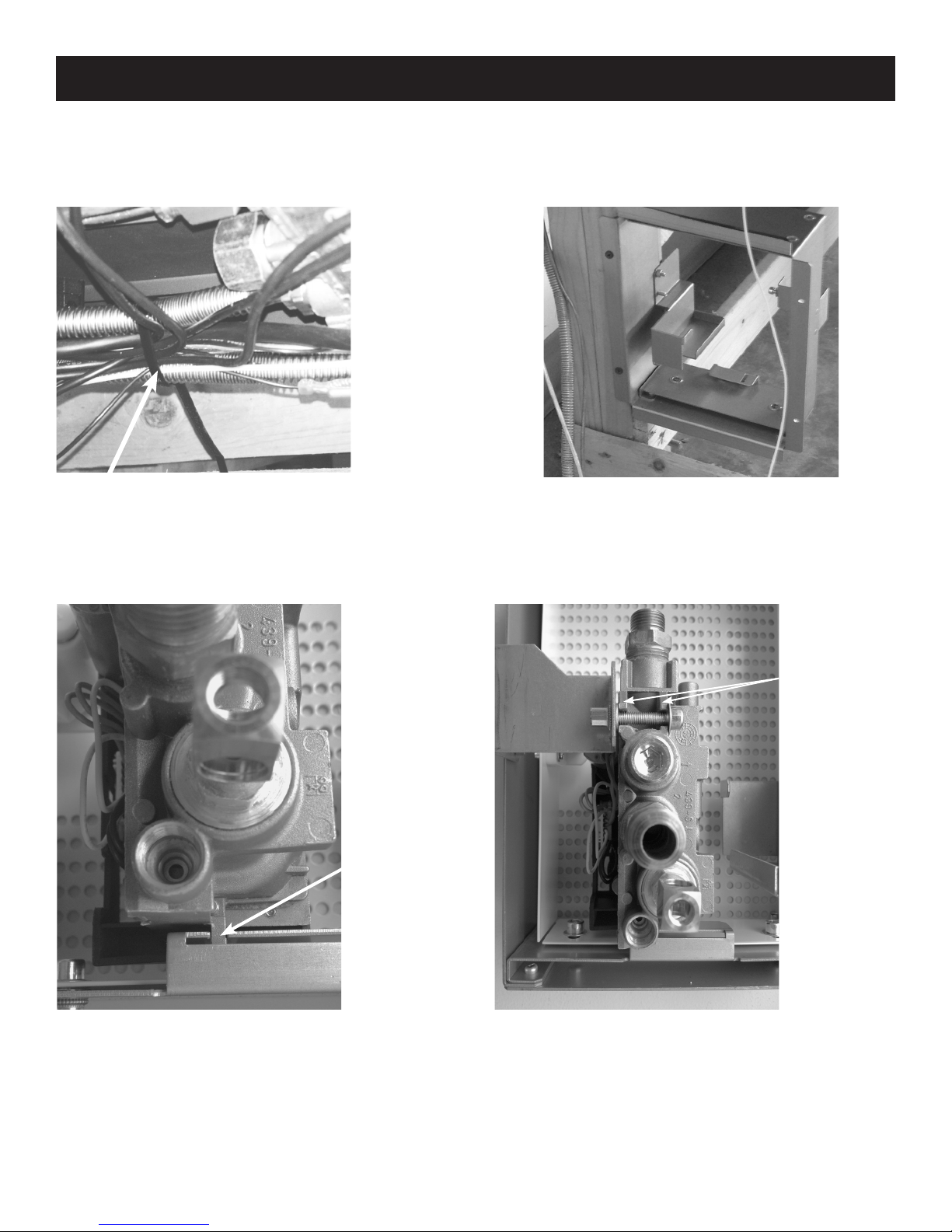
- Carefully cut the black tie wraps which hold the line set to the bottom of the replace then carefully unwrap the line set. Lay
the line set out towards the location of the Access Door. Do not kink the lineset and do not bend to a radius of less than 2”/50
mm. See Figure 34.
- Remove the four bolts holding the white door/frame cover to the frame. Separate the frame and cover then mount the Access
Door frame to the rough opening as shown in Figure 35.
- Replace the white door/frame cover onto the frame and secure it with the four bolts.
- Fit the gas valve tab into the bracket on the Access Door frame then tighten the bolt through the mounting bosses . See
Figures 36 and 37.
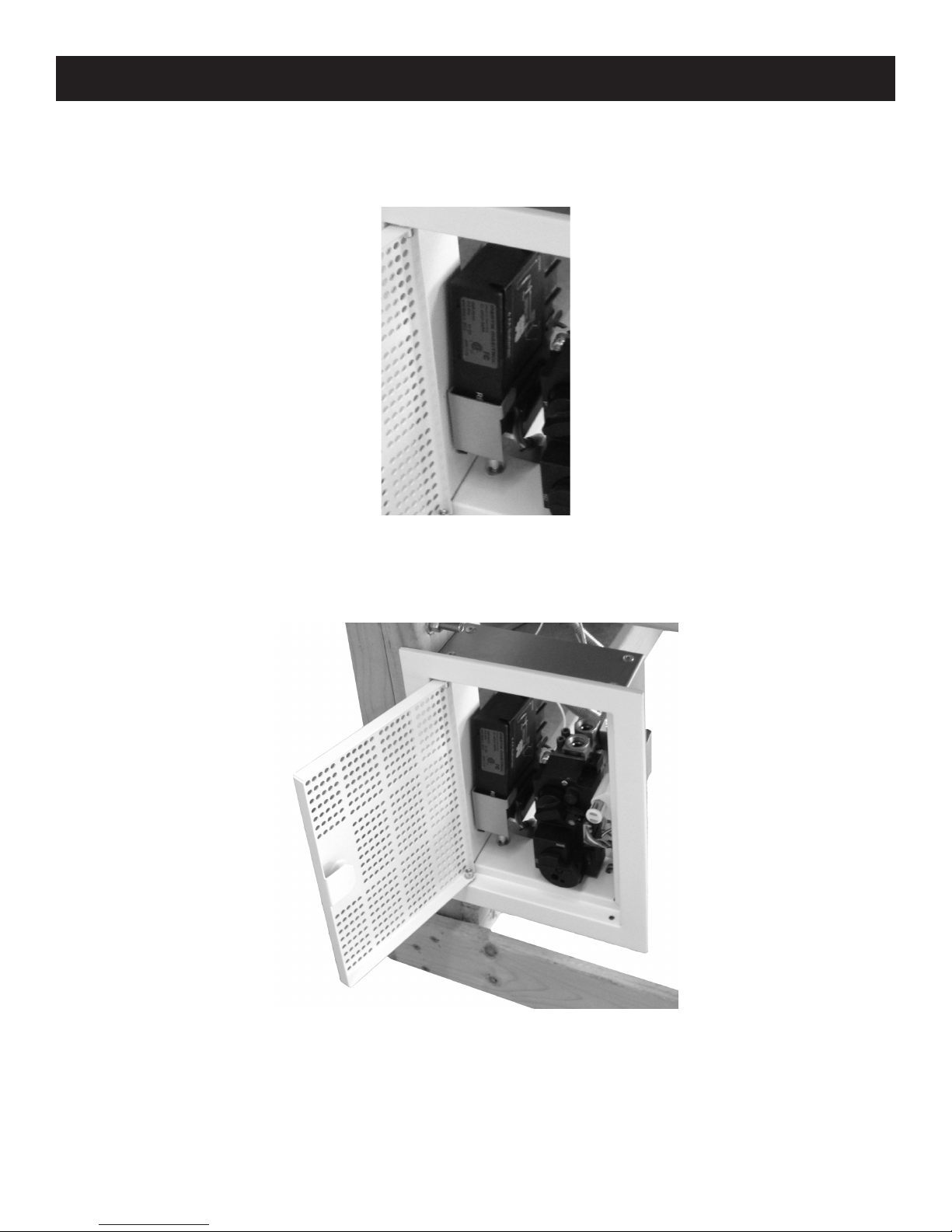
- Set the receiver into the Access Door bracket as shown in Figure 38 and connect the AC adapter.
When mounted, the Access Door should look like that shown in Figure 39.
Element4 Gas Fireplaces EuropeanHome.com
39
Page 40
ENCLOSING the FIREPLACE
One of the tie wraps which secure the line set.
Figure 34
Figure 35 Wall Access Door Frame
Tighten bolt
through
mounting bosses
(at arrows)
Fit tab into bracket
on Access Door
Figure 36
Element4 Gas Fireplaces EuropeanHome.com
Figure 37
40
Page 41
ENCLOSING the FIREPLACE
Figure 38 Receiver in Wall Access Door
Element4 Gas Fireplaces EuropeanHome.com
Figure 39 Access Door Installed
41
Page 42

OPERATING the FIREPLACE
THIS PART WAS INTENTIONALLY LEFT
BLANK
BEFORE THE FIRST FIRE
1. Make certain that all construction materials have been removed from inside and around the replace and the replace has
been cleaned of any construction dust.
2. Conrm that the gas valve is properly connected and bled.
3. Check the gas supply for leaks and proper pressure.
4. Check that the venting is unobstructed and in proper working condition.
5. PROPERLY PLACE, CLAMP, AND SEAL THE GLASS PANELS.
6. Place the three AAA batteries into the remote control and conrm that it will communicate with the receiver by pressing
the ON/OFF. (See Figure 41) If necessary pair the remote and receiver.
7. Follow USING THE REMOTE CONTROL ELECTRONIC IGNITION SEQUENCE to setup and use remote.
Element4 Gas Fireplaces EuropeanHome.com
42
Page 43
OPERATING the FIREPLACE
PAIRING THE REMOTE AND RECEIVER (for rst re and when reset is needed)
From the factory, the remote control will communicate with the receiver; they are ‘paired’ and should need no further attention. If
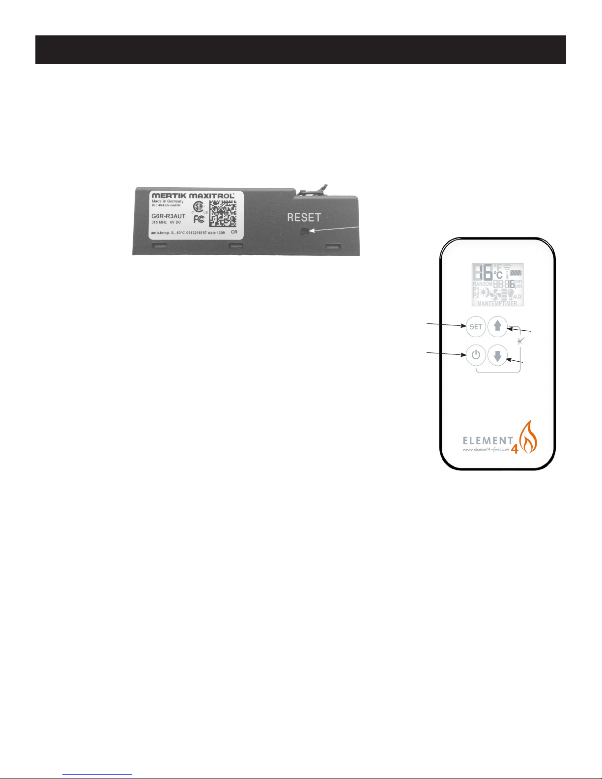
the receiver does not respond to commands from the remote they should be paired to each other. This is done as follows:
1. Press and hold the receiver reset button (Figure 40) using a small, long tool until you hear the second of two beeps. After the
second beep release the reset button.
2. Press and hold the È (down) button on the remote until you hear the second of two beeps. Release the È (down) button.
RESET BUTTON
Figure 40 Receiver
USING THE REMOTE CONTROL ELECTRONIC IGNITION SYSTEM
Note: The system shuts o the appliance completely if there is no change in the ame height
for 5 days.
SET
Setting °C/24 Hour or °F/12 Hour Clock.
Press ON/OFF andÈto toggle between °F/12 hr and °C/24 hr clock.
Setting the time.
Simultaneously press theÈand Çbuttons, the display will ash.
PressÇto set the hour andÈto set the minute.
Press ON/OFF to return to manual mode.
ON/OFF
UP
DOWN
HOW TO LIGHT YOUR FIREPLACE
Igniting the Appliance.
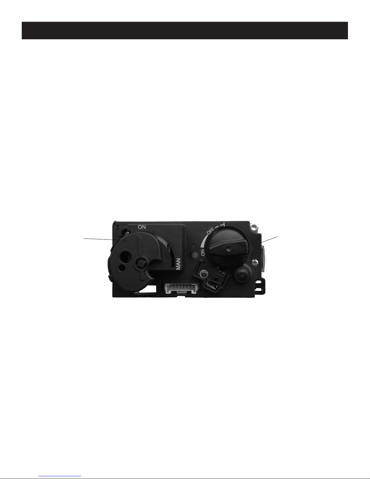
NOTE: During start-up, the MANUAL knob on the gas valve cannot be in the MAN position. It
must be in the ON position. See Figure 42.
On the remote control, simultaneously press and hold the ON/OFF andÇbuttons.
An acoustic signal indicates that the start sequence has begun. Release the buttons.
The electronic system then checks that the main gas is owing and ignites the main burner; this may take up to 20 seconds.
Changing the Mode of Operation.
Briey pressing the SET button changes the mode of operation in the following order:
Man - Temp - Temp - Timer - back to Man
Man - Manual Flame Height Adjustment.
To increase the ame, theÇbutton should be depressed. Pressing theÈbutton on the handset will reduce the ame. The main
ame may be lowered all the way down until it is o, leaving only the pilot ignited. This is called standby mode.
Fully Extinguishing the Appliance
From any heat setting, press the ON/OFF button for a few seconds. This will cause the burner to fully extinguish.
The system has a safety interlock which will not allow the ignition until the interlock rests. This may take a few minutes.
The appliance should be shut o completely using the ON/OFF button on the handset and not left on pilot only, except for
temporary use. This resets the system and all safety features.
Temp - Daytime Temperature mode.
The appliance must be in standby mode, pilot ignited. The room temperature is measured and compared to the set temperature.
The ame height is then automatically adjusted to reach the daytime set temperature.
Element4 Gas Fireplaces EuropeanHome.com
43
Figure 41 Remote Control
Page 44
OPERATING the FIREPLACE
Temp - Nighttime setback Temperature mode.
The appliance must be in standby mode, pilot ignited. The room temperature is measured and compared to the nighttime
setback temperature. The ame height is then automatically adjusted to achieve the nighttime setback temperature.
Timer mode.
The appliance must be in standby mode, pilot ignited. The Timer setting allows you to set 2 burner Temp times and 2 burner
Temp times every 24 hrs.
For Temp to operate as a thermostat, TEMP must be set at 4°C or higher.
If the Temp setting is decreased to - -, the motor will turn the valve to the standby position in the moon times and await the
next burner Temp cycle.
Setting the Temperature.
Select either the Te mp MODE or the Temp MODE by briey pressing the SET button.
Hold the SET button until the TEMP display ashes.
Set the desired temperature withÈorÇ.
Press ON/OFF to complete the program.
Setting the Timer.
Select Timer mode by briey pressing the SET button.
Press and hold the SET button until the P1 is displayed, and the time ashes. Set the hour by pressingÇand set the minutes by
pressingÈ.
Briey press SET button for the next burner cycle time.
Once all 4 times are set, press ON/OFF to complete the programming.
MANUAL KNOB IN
ON POSITION
Figure 42 Gas Valve
Automatic Turndown.
1. In Manual/Temperature/Timer modes, the valve will turn to pilot ame if there is no change in ame height for a six hour
period. In Temperature or Timer mode, if the ambient room temperature changes, the ame height will adjust automatically to
maintain set temperature and the re will continue to function normally. The valve will turn to pilot ame if the set temperature
and the ambient room temperature remain the same over a six hour period.
2. The valve turns to pilot ame if the temperature in the receiver is higher than 140°F/60°C. The main burner comes back on only
when the temperature is below 140°F/60°C.
Automatic Shut O.
MAIN VALVE KNOB
IN OFF POSITION
1. With low battery power in the receiver, the system shuts o the re completely. This does not happen if the power supply is
interrupted.
2. The system shuts o the re completely if there is no change in ame height for 5 days.
3. The system shuts o the re if the main burner does not completely ignite approximately 20 seconds after ignition or after
pushing the Ç button.
Element4 Gas Fireplaces EuropeanHome.com
44
Page 45
OPERATING the FIREPLACE
TEST FIRE
Prior to being placed into operation, the replace should be test-red in stages to ensure that all components are in good working
order. This replace has a 2nd thermocouple which senses the main burner ame. The system will turn itself o if the system does
not sense the 2nd thermocouple output within 20 seconds after the main valve opens.
Note that a single, long beep indicates that the 2nd thermocouple is still hot enough to produce electricity at the receiver which will
not allow the replace to start. Allow time for the 2nd thermocouple to cool down before attempting a start. The system is ready to
start when pressing the ON/OFF button produces a response from the valve.
1. Start the replace without the hearth panel in place and with the front glass o. Ensure that the pilot ame both heats the
primary thermocouple and lights the main burner. For safety, a post-purge delay is built into the system. Subsequent start
attempts MUST NOT take place for at least ve (5) minutes.
2. Start the replace with the hearth panel in place and with all of the glass panels xed correctly in place. Ensure that the
main burner ames engulf the 2nd thermocouple and the replace stays lit for at least 1 full minute. If the system turns itself
o after 20 seconds install the required media (next section) and return here. Installing the re media will help with the
ame around the 2nd thermocouple. Subsequent start attempts MUST NOT take place for at least ve (5) minutes.
3. Start the replace with the media installed. If the system turns itself o after 20 seconds, rearrange the media to produce
a good ame at the 2nd thermocouple. This step may have to be repeated several times before the media is in the best
place for consistent operation. A single, long beep indicates that the 2nd thermocouple is still too hot to start the ignition
sequence. Allow time for the 2nd thermocouple to cool down. Once the system stays lit for at least one full minute, turn
the replace o, x the glass panels in place and operate the replace for at least 45 minutes to ensure the system works
properly when heated.
THE FIRST FIRE
When the replace is rst heated, an odor may be given o by the hot metal. This is normal and is a result of the ‘burn o’ of the
lubricants and sealants used when manufacturing the replace. We recommend that you open the nearby windows for extra
ventilation and then operate the replace for at least four hours.
When the glass is cold, some condensation may appear on the glass after lighting the replace. This is normal and the
condensation will disappear as the glass warms.
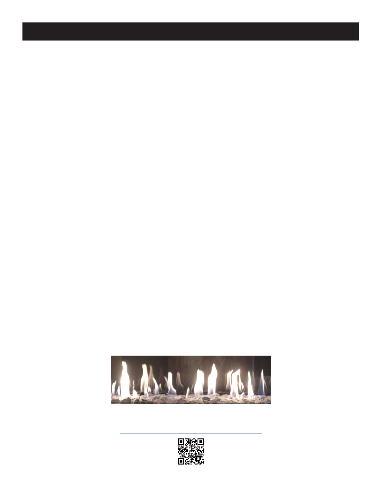
During this rst re, examine the ame for appearance and quality. Examine the burner media for sooting. The ames should look
like those shown in Figure 43.
After this burn-o period, turn o the replace and let it cool completely to room temperature and clean both sides of the glass as
described in the MAINTENANCE section.
Since it is a metal replace, the heat-up and cool-down cycles may produce some noises caused by the expansion and contraction
of these metals. The premium materials and build quality of your replace will keep these sounds to a minimum.
Figure 43
To see an Element4 replace starting and running normally
please visit the link below.
WWW.EUROPEANHOME.COM/RESOURCES/VIDEOS/
Element4 Gas Fireplaces EuropeanHome.com
45
Page 46
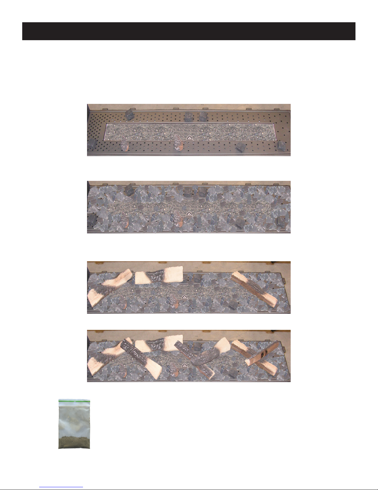
INSTALLING THE FIRE MEDIA
LOG ARRANGEMENTS ALL LUCIUS MODELS
Ensure that the hearth panel is sitting rmly in the base of the re box with the long slot in the center of the panel aligning with
the top of the burner. The pilot ame must be visible through the panel and the cut-out in the pilot shield. Place the six coals and
two cones as shown in Figure A. Ensure that the area near the pilot ame is left clear.
A
Position the embers as shown in Figure B.
B
Figures C and D show detail of the positioning of the logs.
c
D
The bag of ash (shown on the left) comes with your logset. Its purpose is to make the logs look
more realistic. The use of this ash is optional.
To use:
-Sprinkle the ash onto the logs as desired.
-Make sure that the ash DOES NOT get inside of the burner ports. If so, clogging may occur.
Element4 Gas Fireplaces EuropeanHome.com
46
Page 47
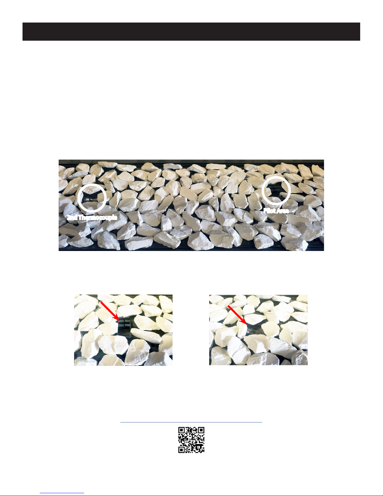
INSTALLING THE FIRE MEDIA
STONES/GLASS ARRANGEMENTS
Ensure that the hearth panel is sitting rmly on the base of the re box and the shield is installed around the 2nd thermocouple.
The center panel must be inserted in between the burner tubes. The pilot ame must be visible through the hearth panel and the
pilot shield.
Evenly scatter the contents of the bag of stones/glass over the top of the hearth panel and burner. Ensure that none of the stones/
glass enters the pilot area or restricts the operation of the 2nd thermocouple.
The arrangement is now complete. However, it is important to check that the pilot ame is still visible.
A shows the arrangement for stones; the arrangement for glass is similar.
A
2nd Thermocouple
B shows the pilot area (arrow) clear of media.
C shows the 2nd thermocouple area (arrow) clear of media.
B
Pilot Area
c
To see how to arrange media in an Element4 replace
WWW.EUROPEANHOME.COM/RESOURCES/VIDEOS/
Element4 Gas Fireplaces EuropeanHome.com
please visit the link below.
47
Page 48
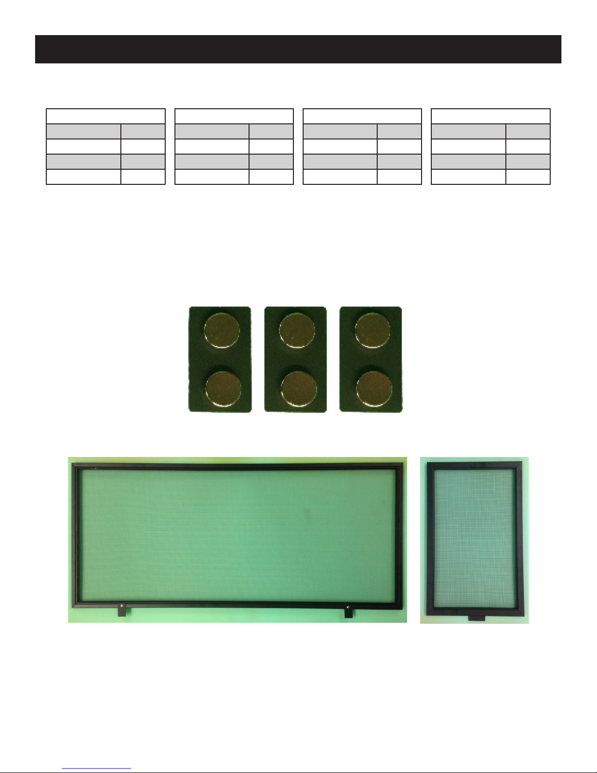
SCREEN INSTALLATION
LUCIUS 140 RD
Tab s
Magnets
Long Screen 2
Short Screen 1
LUCIUS 140 T
Tab s
Magnets
Long Screen 2
Short Screen N/A
LUCIUS 140 1/3
Tab s
Magnets
Long Screen 2
Short Screen 1
LUCIUS 140 2/3
Tab s
Magnets
Long Screen 2
Short Screen 2
(Long Screen) (Short Screen)
Element4 Gas Fireplaces EuropeanHome.com
48
Page 49
SCREEN INSTALLATION
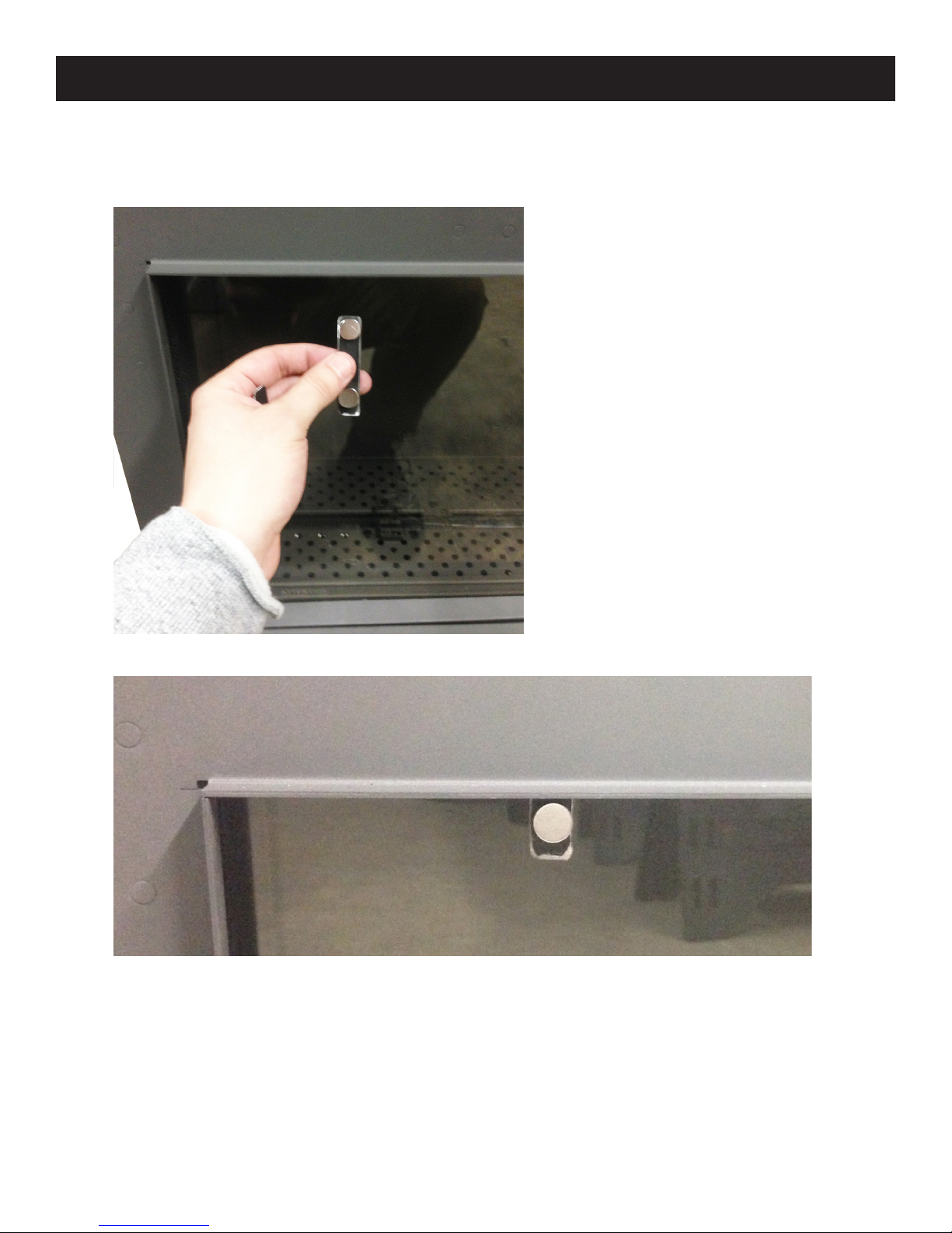
Take one tab and place (2) magnets on each end,
pictured on the left. Once magnets are on, place
tab under the frame/ange, about 4” away from
the top left viewable corner (see photo below).
Once installed on the top left viewable corner, the tab installed should look like the photo above. One magnet
will be holding the tab in place (not visible) and the other magnet will hold the screen to the front of the unit.
Element4 Gas Fireplaces EuropeanHome.com
49
Page 50
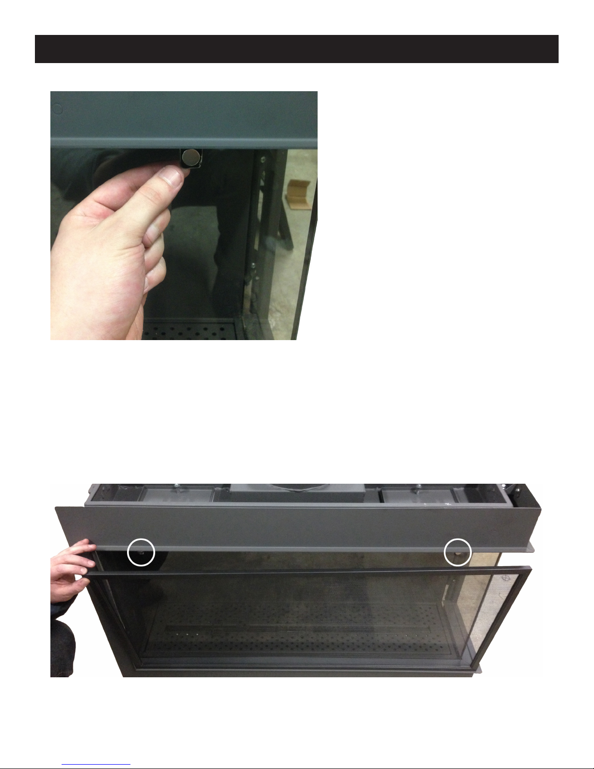
SCREEN INSTALLATION
Please install the tab on the opposite top corner,
in this case, the top right viewable opening. After
installed, the tab should look like the photo on
the left.
Once the (2) top tabs are installed correctly, place the long screen’s (2) bottom tabs in the gap between the bottom trim and
the ange. They should fall into place without any eort or resistance.
Tilt the screen towards the top (2) tabs as shown below, magnets will catch the screen and hold it into place.
Element4 Gas Fireplaces EuropeanHome.com
50
Page 51
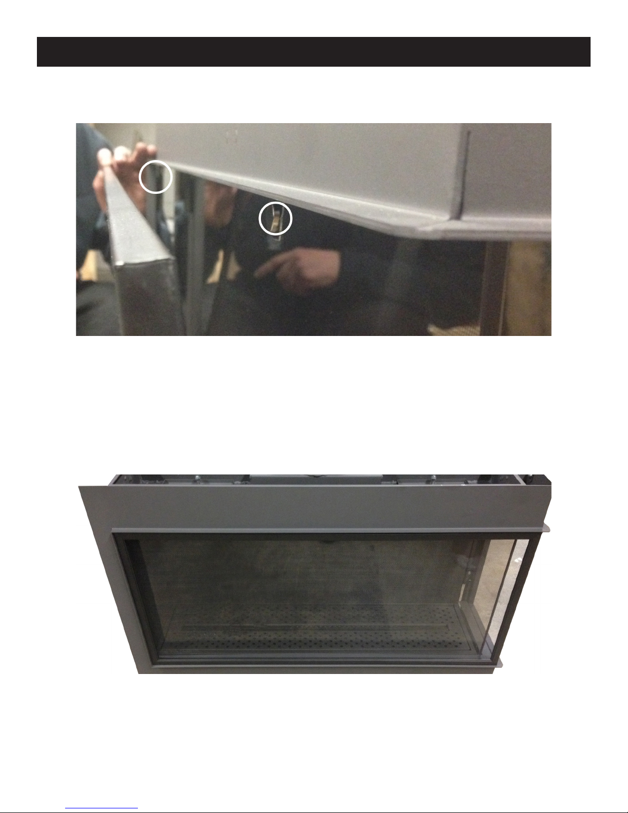
SCREEN INSTALLATION
Here is another view of the (2) top tabs in place before the screen is tilted into position.
This is the nal view of the front long screen installed correctly.
Element4 Gas Fireplaces EuropeanHome.com
51
Page 52
SCREEN INSTALLATION
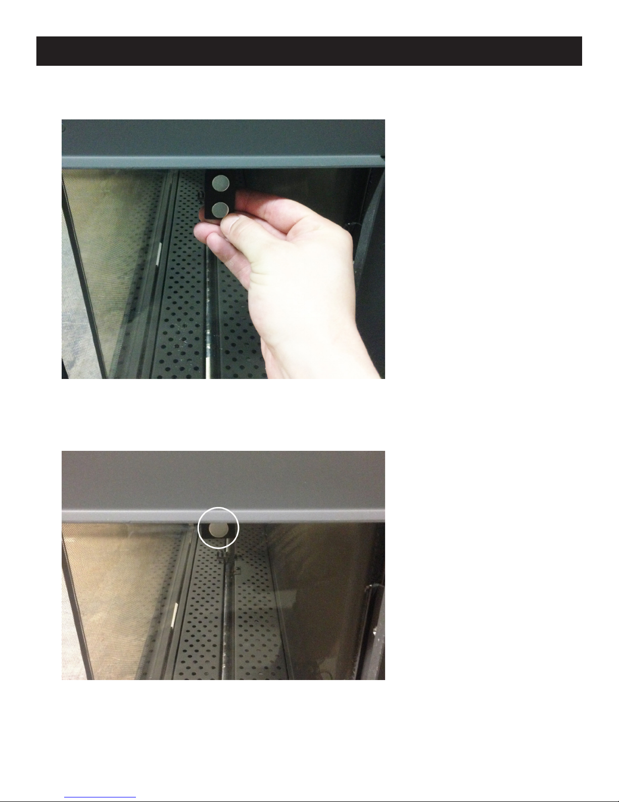
The side small screen installation
process will be very similar to the front
long screen. Keep in mind that there is
only (1) tab to be installed on the top,
with a magnet holding the tab to the
unit and the other magnet visible as
shown below.
The tab should look like the photo on
the left once installed correctly.
Element4 Gas Fireplaces EuropeanHome.com
52
Page 53
SCREEN INSTALLATION
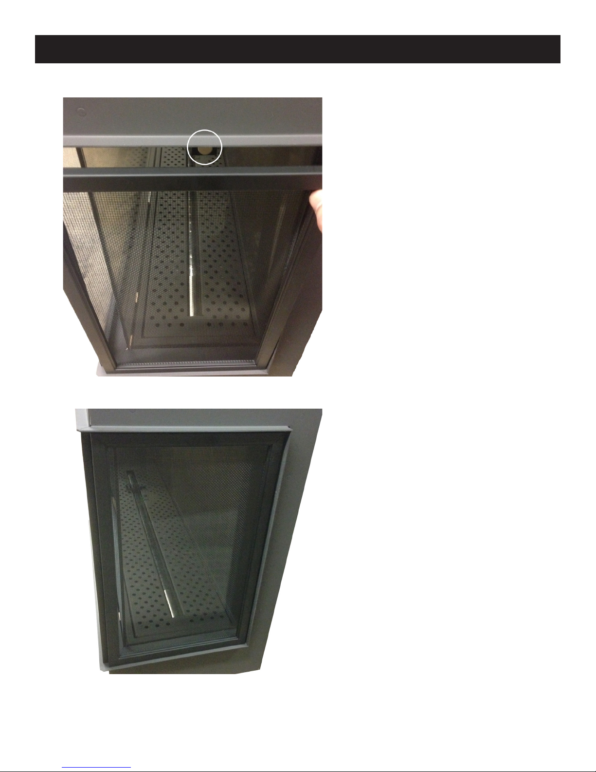
Once the top tab is installed, place the bottom of the
side short screen into place, with the bottom tab of
the screen placed between the trim and the ange.
Tilt the screen towards the top of the unit until the
tab catches the screen and holds it into place, circled
in the photo on the left.
Once installed properly the screen should look like
the photo to the left.
If needed, slide the screen gently left or right until
the edges of the screen touch.
Element4 Gas Fireplaces EuropeanHome.com
53
Page 54
SCREEN INSTALLATION
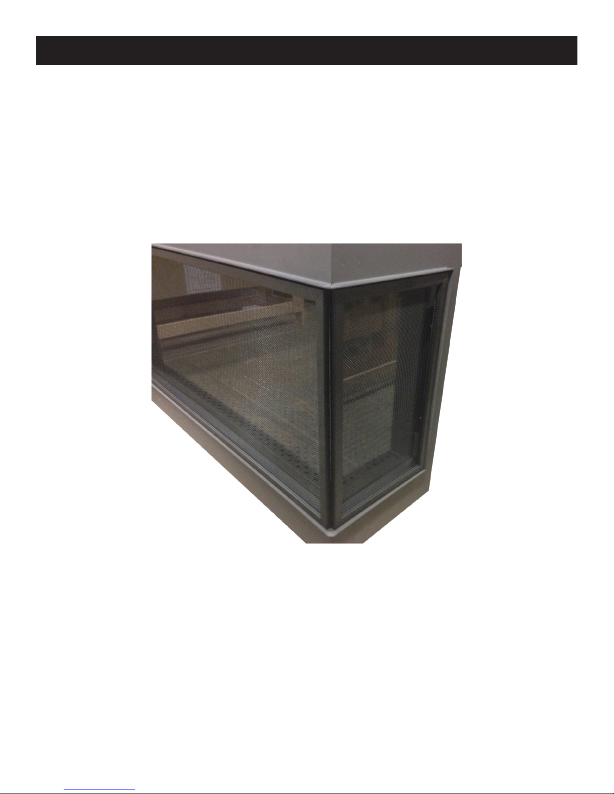
This is the nal look of a screen installed correctly.
Element4 Gas Fireplaces EuropeanHome.com
54
Page 55
MAINTENANCE
REMOVING AND CLEANING THE GLASS
OVERVIEW
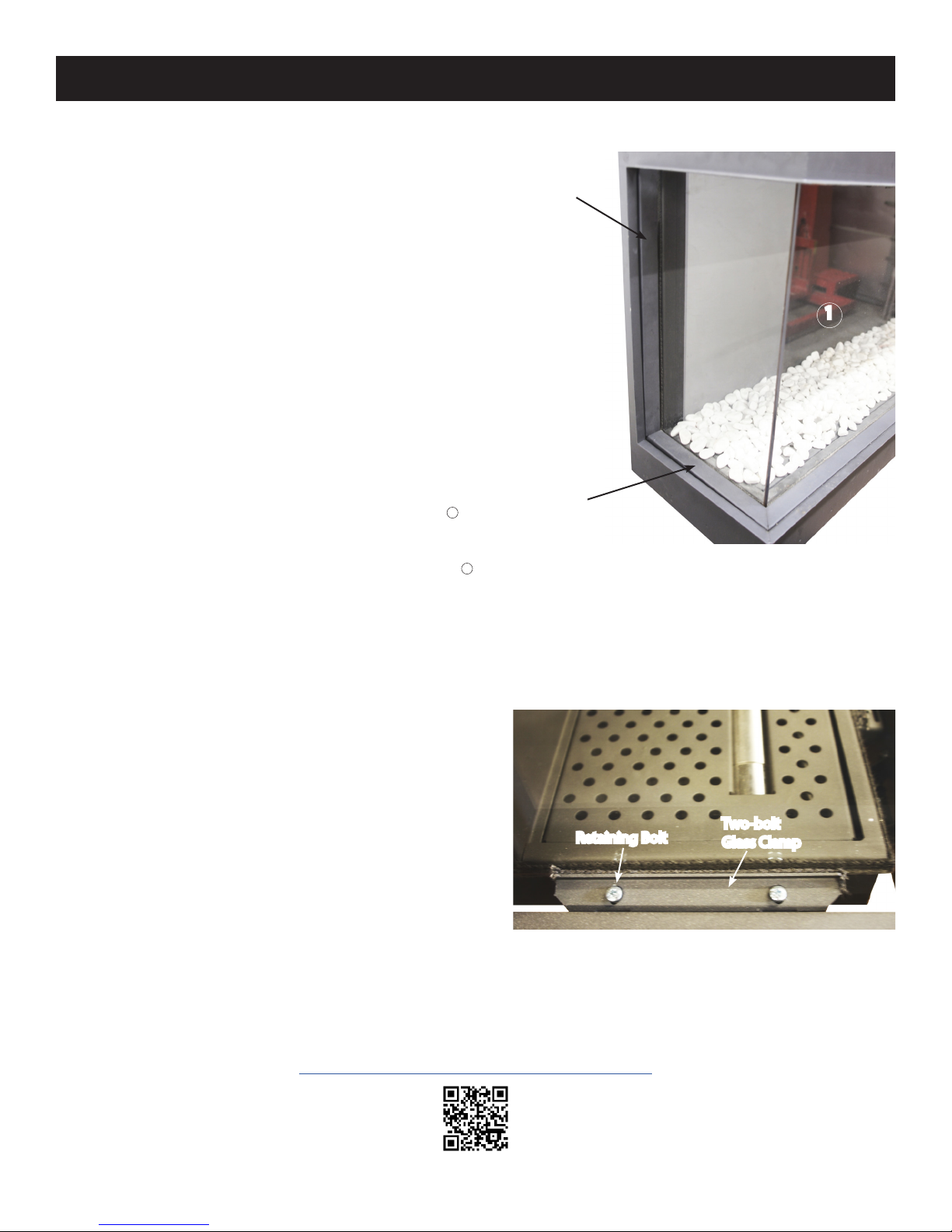
The glass panels on this replace are held in place by a number of
retaining bolts and gasketed clamps. These instructions will show
you how to remove and install the clamps and glass panels.
Please read these instructions completely before proceeding.
Side Trim
TOOLS REQUIRED
• No. 2 Phillips screwdriver (not included)
• Gloves (not included)
• Suction Cup
BEFORE YOU BEGIN
Ensure the glass is not hot.
Except for tunnel, the rst glass panel to be removed is the one
which is not touching a gasketed edge. This panel is marked 1 in
Figure 44.
• On Lucius models with three glass panels the small panel is
Note: Some models have two sizes of glass clamps; a two-bolt clamp
and a one-bolt clamp. Figure 45 shows the two-bolt clamp.
1
.
REMOVING THE GLASS
Step 1.
Remove all of the trim pieces from the replace. The location and
quantity of trim varies with model but in every case there is no top
trim. The trim pieces are held rmly in place with magnets and will
simply lift out. The bottom (horizontal) trim pieces are at the lower
edge of the glass panels and the side (vertical pieces) are where the
glass meets the wall.
Bottom Trim
Retaining Bolt
1
Figure 44
Two-bolt
Glass Clamp
Step 2.
Gasketed glass clamps hold the edges of the glass panel in place.
The quantity and location of the clamps vary by model. Remove the
retaining bolt(s) holding the glass clamp and then remove the clamp.
Remove all of the retaining bolts and clamps holding in the rst
piece of glass.
To see how to remove the glass from an Element4 replace
WWW.EUROPEANHOME.COM/RESOURCES/VIDEOS/
Element4 Gas Fireplaces EuropeanHome.com
Figure 45
please visit the link below.
55
Page 56
MAINTENANCE
Step 3.
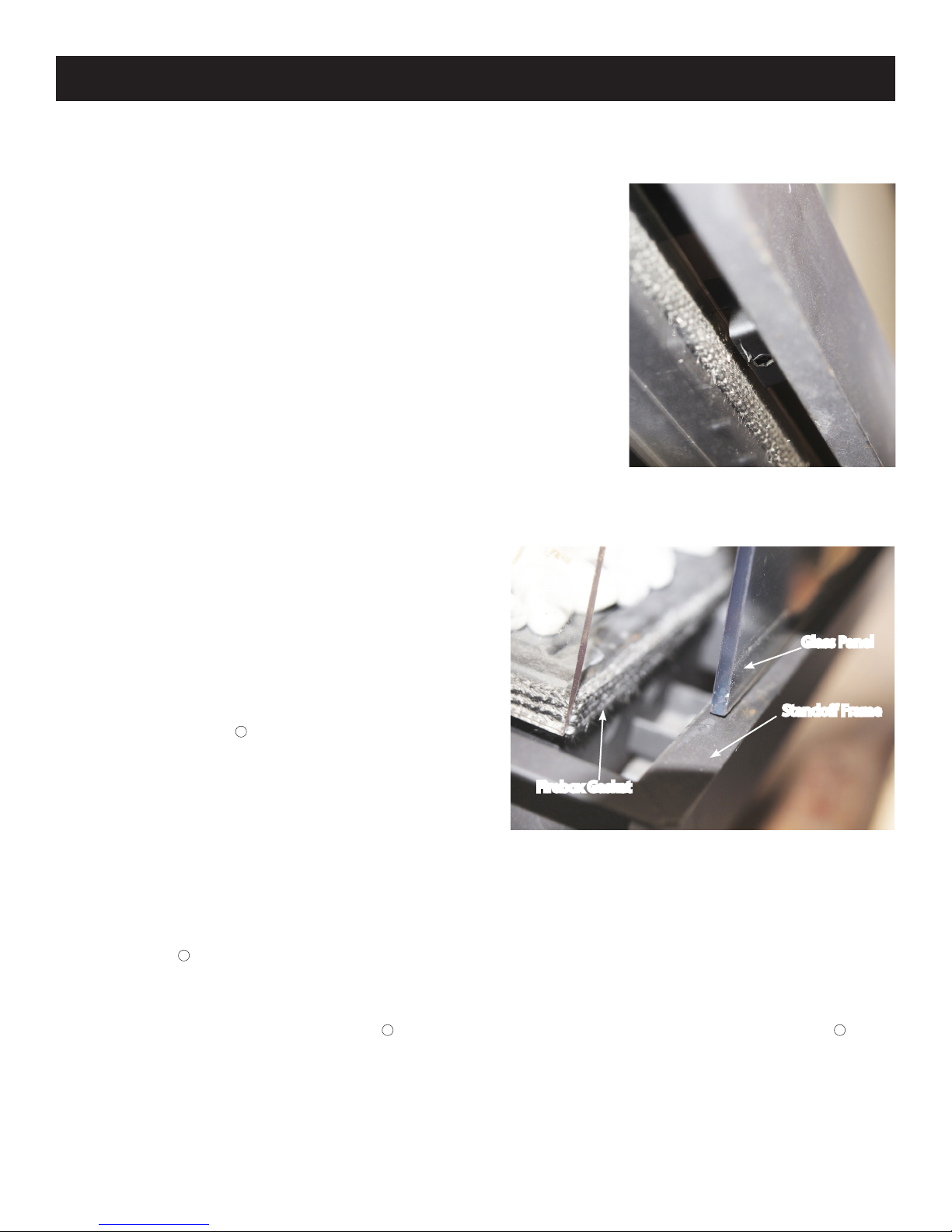
Attach the vacuum glass clamp to the center of the glass and lift the glass up into
the clearance notch.
When the glass panel is raised into the clearance notch there is enough clearance
to swing the lower edge of the glass panel over the stando frame. See Figure 47.
When the glass panel is outside of the stando frame then lower the glass panel
out of the clearance notch and carefully, and securely, set the panel aside.
Step 4.
Repeat Steps 2 and 3 for the other glass panels.
CLEANING THE GLASS
The glass should be cleaned as necessary with a replace glass
cleaner. We recommend Stove Bright® Gas Appliance Glass
Cleaner by Forrest Paint Co. It is available through your retailer.
Follow the instructions for use and do not clean the glass when it
is hot! If the glass becomes coated with deposits which cannot be
removed it must be replaced.
Figure 46
Glass Panel
INSTALLING THE GLASS
The glass panels should be installed in reverse order of their removal
beginning with glass panel .
Step 1.
Lift the glass panel up into the clearance notch and swing the lower
edge of the glass panel against the rebox gasket. (See Figure 47) Set
a glass clamp into place and hold it loosely into place with a retaining
bolt. DO NOT tighten the retaining bolt yet.
Step 2.
Repeat Step 1 with the remaining glass panels.
Step 3.
Center glass panel 1, left and right, on the replace and screw the retaining bolts into the lower glass clamp until the bolts touch
the glass clamp. Repeat for the remaining glass clamps on this glass panel.
Step 4.
Slide the adjoining glass panel against glass panel 1. If there is a second adjoining glass panel slide it against glass panel 1.
Step 5.
While ensuring that the glass panels are tight and square to each another, tighten the retaining bolt(s) on each clamp NO MORE
THAN ½ TURN.
1
Firebox Gasket
Figure 47
Stando Frame
PROPERLY PLACE, CLAMP AND SEAL THE GLASS PANEL(S) BEFORE LIGHTING THE FIRE!
Element4 Gas Fireplaces EuropeanHome.com
56
Page 57
MAINTENANCE
Pilot Injector Natural - Marking 31.2
Pilot Injector Propane - Marking 27.1
3mm
BURNER MAINTENANCE
The ames from the burner should be visually checked. The ame should have a blue base and yellow tops and be candle-like in
appearance.
PILOT MAINTENANCE
The pilot ame must be visually checked. The pilot ame must always be present when the appliance is in operation and should
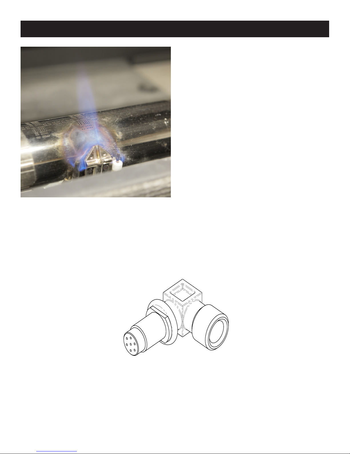
appear as in Figure 49 (shown with hearth panel removed.)
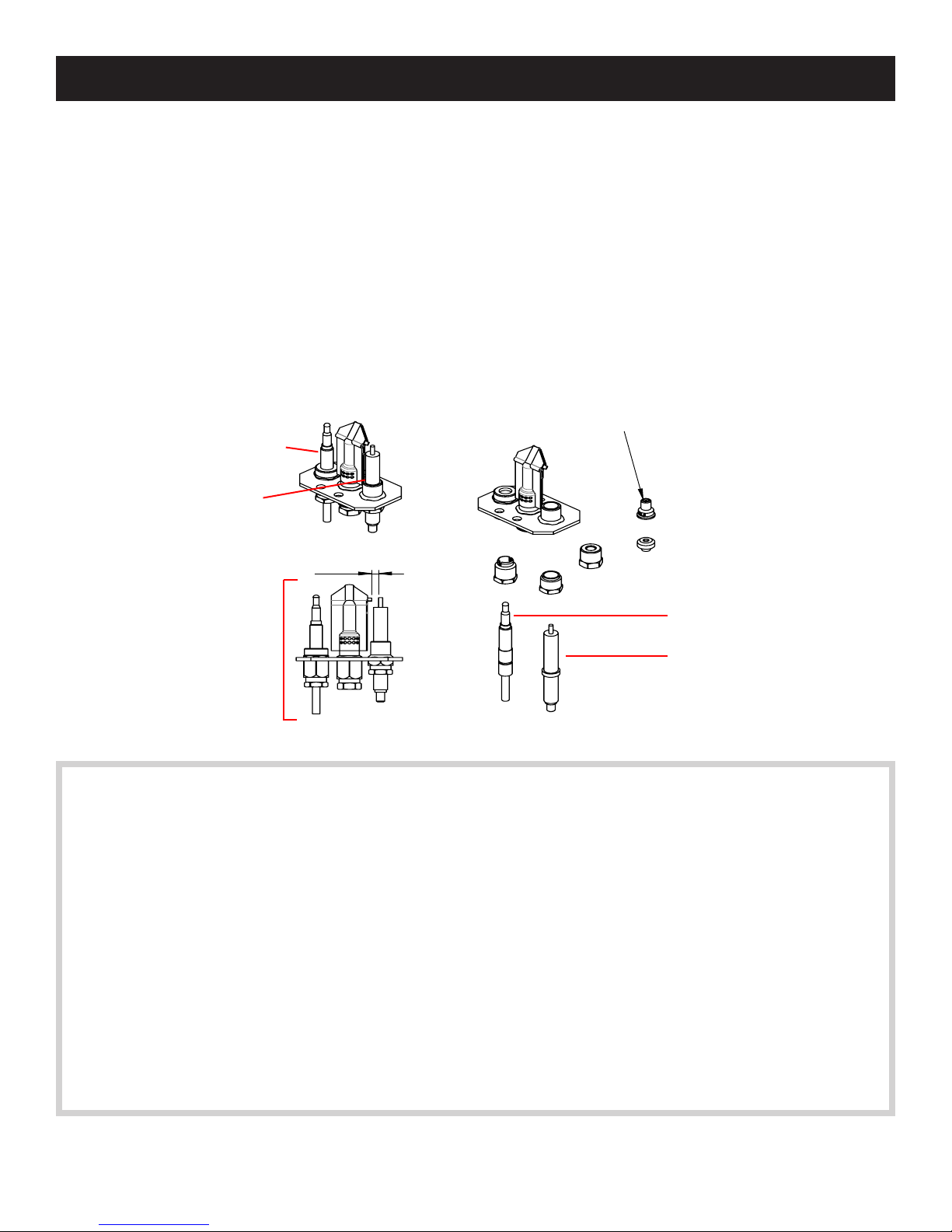
The pilot has two distinct ames, one engulng the thermocouple on it’s left, the other reaching across to the main burner.
The area around the pilot should be inspected. Lint or foreign material must be removed with a brush or vacuum.
Thermocouple
Ignitor Rod
Thermocouple
Pilot Assembly
Figure 48 Pilot Assembly Detail
Ignitor Rod
(styles vary)
WARNING
Installation and maintenance must be performed by an authorized qualied installer, service agency or gas supplier.
TURN OFF THE GAS before servicing the appliance. It is recommended that a qualied service technician perform an
appliance check-up/service once a year.
Any safety screen or guard removed for servicing MUST BE REPLACED before operating this appliance.
DO NOT USE this appliance if any part has been under water. Immediately call a qualied service technician to inspect the
unit and to replace any part of the control system and any gas valve that has been under water.
Any alteration to the product that causes soot or carbon to form and results in damage is not the responsibility of the
manufacturer.
Inspect the external vent cap on a regular basis to make sure that no debris, plants, trees, or shrubs are interfering with the
air ow.
Element4 Gas Fireplaces EuropeanHome.com
57
Page 58
Natural Gas Injector - marked 1200
Propane Gas Injector - marked 320
Figure 49
MAINTENANCE
THERMOCOUPLE MAINTENANCE
The Element4 replaces have two thermocouples; one next to
the pilot and one opposite the pilot side of the main burner. The
completeness and operation of both must be checked. A qualied
installer must conrm that both thermocouples are in place and
not damaged. While checking the thermocouple, please ensure
that the ignitor rod is not cracked as well.
VENT MAINTENANCE
The following venting system inspection by a qualied service
technician is recommended every six months:
1. Inspect for excessive condensation, e.g. water droplets
forming in the inner lining and subsequently dripping out
of the joints. This can cause corrosion in the system.
2. Check for corrosion in areas exposed to the elements.
Where rust spots or holes have appeared, these must be
immediately replaced.
3. Ensure that there is no foreign material in the vents. Survey
by removing the cap and shining a light down the vent.
4. Check all joints and pipes to make sure that nothing has
been disturbed or loosened.
REPLACEMENT PARTS
The orice for the burners is shown in Figure 50. The NG orices are marked 1200, LP orices are marked 380.
Figure 50
E4-SA-LPCK-140-04 LP Conversion Kit
REPL-E4-GS-1T-01 Replacement Primary Thermocouple
REPL-E4-GS-2TC-01 Replacement 2nd Thermocouple
REPL-E4-GS-CM-01 Replacement Receiver
REPL-E4-GS-RC-01 Replacement Remote Control
Element4 Gas Fireplaces EuropeanHome.com
58
Page 59
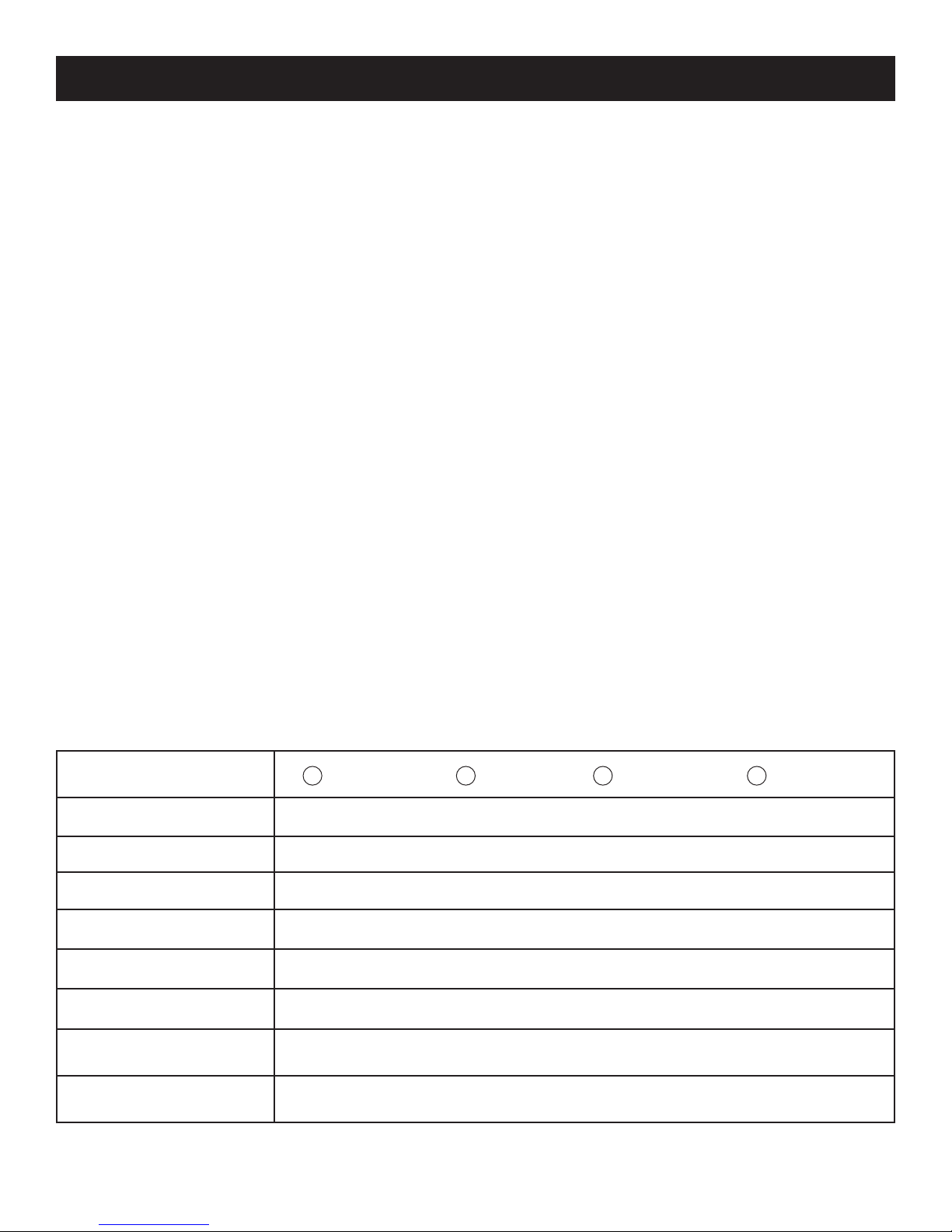
WARRANTY
European Home Warranty
Element4 Gas Fireplace
European Home warrants these gas fireplaces against defects in materials and workmanship for a period of ONE (1) YEAR
from the date of original retail purchase. Glass is expressly NOT covered by this warranty.
If a defect exists, European Home will, at its option, either (1) provide needed components using new or refurbished
replacement parts or (2) exchange the product with one which is new or which has been manufactured from new or
serviceable used parts and is at least functionally equivalent to the original product. A replacement product/part assumes
the remaining warranty of the original product or ninety (90) days from the date of replacement or repair, whichever
provides longer coverage for you. When a product or part is exchanged, any replacement item becomes your property and
the replaced item becomes the property of European Home. All warranty claims must be submitted through the dealer
from which you purchased the product. Check with your dealer in advance for any costs to you when arranging a warranty
call. Shipping and/or delivery charges for parts are not covered by this warranty.
Nothing in the above shall be deemed to imply that this warranty shall apply to work which has been abused or neglected
or shows evidence of changes or modifications by others with or without permit, damages caused by the acts of God,
building settlement or moving, fire or vandalism. In addition, installation of this product that varies from the requirements
stated in the instruction manual will void the warranty.
PRODUCT INSTALLATION RECORD
Installer: Please complete this form. Customer: Please retain this information.
Model (check one) Lucius 140 RD Lucius 140 T Lucius 140 1/3 Lucius 140 2/3
Purchased From
Date of Purchase
Installed By
Date of Installation
Fireplace Serial Number
Fuel Type
Total Venting Horizontal
Total Venting Vertical
Element4 Gas Fireplaces EuropeanHome.com
59
Page 60

APPENDIX ONE
MASSACHUSETTS CERTIFICATION
This appliance is approved for installation in the Commonwealth of Massachusetts. The Board of State Examiners of Plumbers and
Gas Fitters has issued approval number G1-0515-495 for this appliance.
The following must be observed when installing the Element4 replaces within the Commonwealth of Massachusetts:
(a) For all side wall horizontally vented gas fueled equipment installed in every dwelling, building or structure used in whole
or in part for residential purposes, including those owned or operated by the Commonwealth and where the side wall exhaust
vent termination is less than seven (7) feet above nished grade in the area of the venting, including but not limited to decks and
porches, the following requirements shall be satised:
1. INSTALLATION OF CARBON MONOXIDE DETECTORS. At the time of installation of the side wall horizontal vented gas
fueled equipment, the installing plumber or gastter shall observe that a hard wired carbon monoxide detector with an alarm
and battery back-up is installed on the oor level where the gas equipment is to be installed. In addition, the installing plumber
or gastter shall observe that a battery operated or hard wired carbon monoxide detector with an alarm is installed on each
additional level of the dwelling, building or structure served by the side wall horizontal vented gas fueled equipment. It shall be
the responsibility of the property owner to secure the services of qualied licensed professionals for the installation of hard wired
carbon monoxide detectors
a. In the event that the side wall horizontally vented gas fueled equipment is installed in a crawl space or an attic,
the hard wired carbon monoxide detector with alarm and battery back-up may be installed on the next adjacent oor
level.
b. In the event that the requirements of this subdivision can not be met at the time of completion of installation, the
owner shall have a period of thirty (30) days to comply with the above requirements; provided, however, that during said
thirty (30) day period, a battery operated carbon monoxide detector with an alarm shall be installed.
2. APPROVED CARBON MONOXIDE DETECTORS. Each carbon monoxide detector as required in accordance with the above
provisions shall comply with NFPA 720 and be ANSI/UL 2034 listed and IAS certied.
3. SIGNAGE. A metal or plastic identication plate shall be permanently mounted to the exterior of the building at a
minimum height of eight (8) feet above grade directly in line with the exhaust vent terminal for the horizontally vented gas fueled
heating appliance or equipment. The sign shall read, in print size no less than one-half (½) inch in size, "GAS VENT DIRECTLY
BELOW. KEEP CLEAR OF ALL OBSTRUCTIONS".
4. INSPECTION. The state or local gas inspector of the side wall horizontally vented gas fueled equipment shall not approve
the installation unless, upon inspection, the inspector observes carbon monoxide detectors and signage installed in accordance
with the provisions of 248 CMR 5.08(2)(a)1 through 4.
(b) EXEMPTIONS: The following equipment is exempt from 248 CMR 5.08(2)(a)1 through 4:
1. The equipment listed in Chapter 10 entitled "Equipment Not Required To Be Vented" in the most current edition of
NFPA 54 as adopted by the Board; and
2. Product Approved side wall horizontally vented gas fueled equipment installed in a room or structure separate from
the dwelling, building or structure used in whole or in part for residential purposes.
(c) MANUFACTURER REQUIREMENTS - GAS EQUIPMENT VENTING SYSTEM PROVIDED. When the manufacturer of Product
Approved side wall horizontally vented gas equipment provides a venting system design or venting system components with the
equipment, the instructions provided by the manufacturer for installation of the equipment and the venting system shall include:
1. Detailed instructions for the installation of the venting system design or the venting system components; and
2. A complete parts list for the venting system design or venting system.
(d) MANUFACTURER REQUIREMENTS - GAS EQUIPMENT VENTING SYSTEM NOT PROVIDED. When the manufacturer of a
Product Approved side wall horizontally vented gas fueled equipment does not provide the parts for venting the ue gases, but
identies "special venting systems", the following requirements shall be satised by the manufacturer:
1. The referenced "special venting system" instructions shall be included with the appliance or equipment installation
instructions; and
2. The "special venting systems" shall be Product Approved by the Board, and the instructions for that system shall
include a parts list and detailed installation instructions.
(e) A copy of all installation instructions for all Product Approved side wall horizontally vented gas fueled equipment, all
venting instructions, all parts lists for venting instructions, and/or all venting design instructions shall remain with the appliance or
equipment at the completion of the installation.
Element4 Gas Fireplaces EuropeanHome.com
60
Page 61
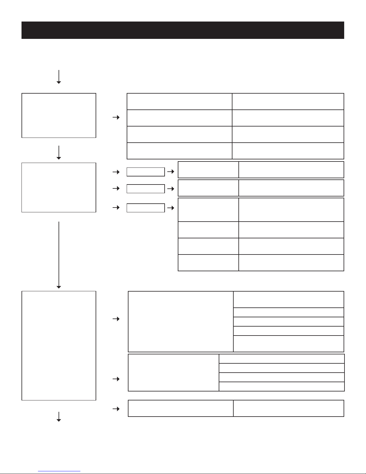
APPENDIX TWO
START
FUNCTION POSSIBLE CAUSE REMEDY
1.
Press UP and OFF buttons
to start ignition sequence.
Beep will occur each
second.
Yes
2.
Magnet unit is energized
thus producing an obvious
latching sound.
Yes
No
No
No
No
Transmitter batteries low.
Receiver batteries low.
Check that transmitter and receiver are
synchronized.
Transmitter distance is limited.
No beep
3 short beeps
1 long beep
Impulse magnet not
operating properly.
Receiver batteries low.
8-wire cable is o or
not operating
properly.
SW-cable
disconnected.
Motor not operating
properly.
Micro switch not
operating properly.
Replace transmitter batteries. Quality
alkaline recommended.
Replace receiver batteries. Quality 1.5V AA
alkaline recommended.
Reset system, see the installation manual
or the label on the receiver.
1. Straighten the antenna.
2. Replace the receiver.
Replace gas valve.
Replace receiver batteries. Quality 1.5V
AA alkaline recommended.
Conrm proper operation of the 8-wire
cable.
Conrm proper operation of the SWcable.
Replace gas valve.
Replace gas valve.
No
3.
Spark will occur
each second.
No
Yes
(continued)
Element4 Gas Fireplaces EuropeanHome.com
No
Ignition components not
operating properly.
Ignition sequence stops, no pilot
ame.
No reaction to transmitter
command.
Ignition sequence stops, no pilot ame.
Transmitter command is possible.
61
Reset system.
Remove ground bolt and clean ground lug.
Do not coil the ignition cable.
Shorten the ignition cable, if possible.
Check connection between ignition cable
and ignition electrode.
Check ignition electrode spark gap.
Check ignition electrode.
Check ignition cable for damage.
Increase distance between ignition cable
and all metal parts.
Replace receiver batteries. Quality 1.5V AA
alkaline recommended.
Page 62
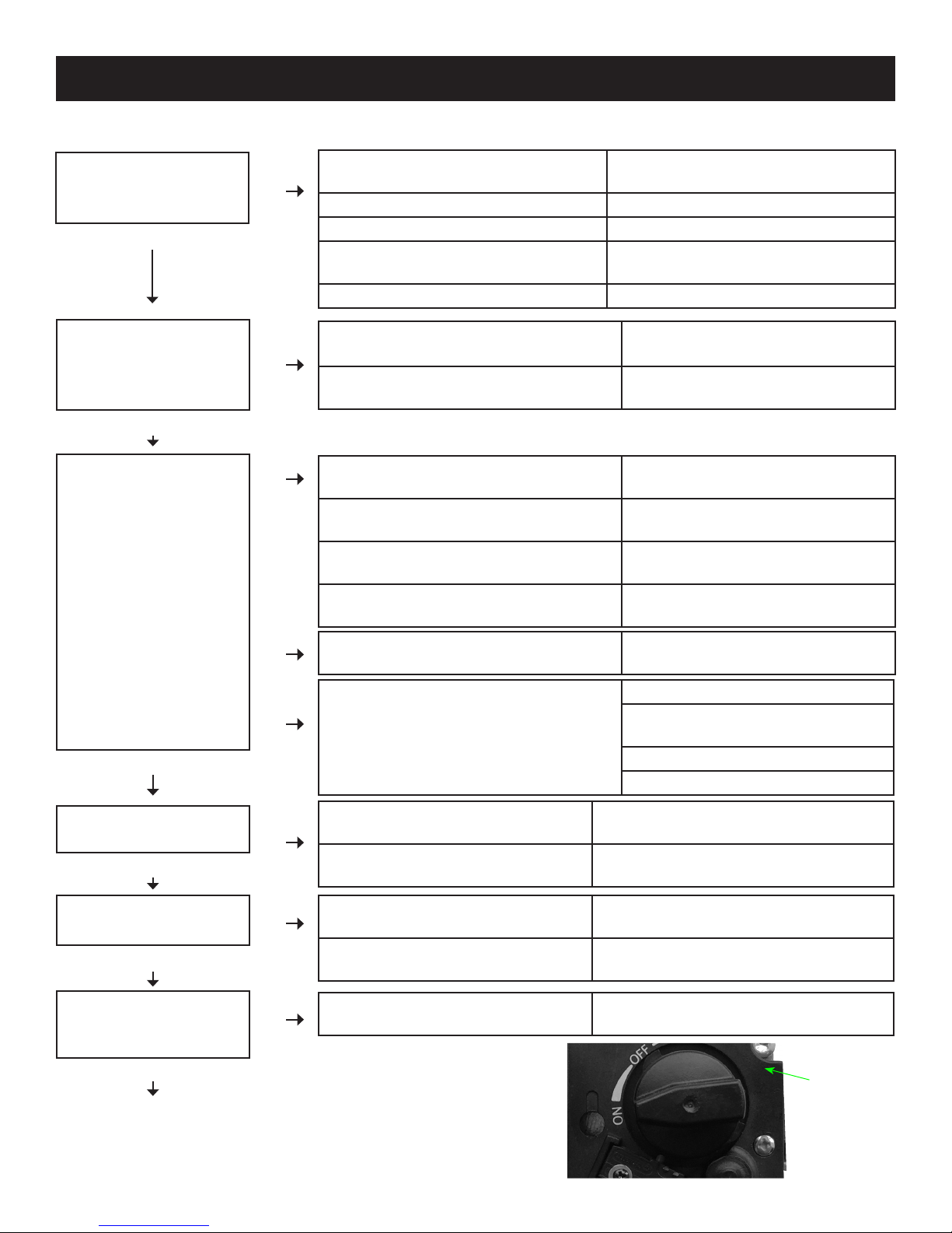
APPENDIX TWO
FUNCTION POSSIBLE CAUSE REMEDY
4.
Pilot lit.
Yes
5.
Sparking stops after
pilot is lit.
Yes
6.
Motor turns to main gas
and pilot stays lit.
No
No
No
Magnet
unit
drops
(audible
sound)
No
TC- and SW-cable reversed.
Magnet unit not operating properly. Replace gas valve.
Short between interrupter and SW cable. Check interrupter block connection.
No gas (magnet unit drops after 30 second
audible count.)
Spark not lighting the pilot. Check spark is crossing pilot orice.
Short between interrupter and
TC-cable.
Electronic measuring amplier defective. Replace the receiver.
Resistance in thermocouple circuit too high. Check thermocouple circuit.
Not enough heat on thermocouple.
Low voltage from thermocouple.
No gas (magnet unit drops after 30 second
audible count.)
Broken receiver
Check cable connection between receiver
and interrupter block.
Check gas supply.
Check connection to interrupter block.
Check position of pilot to thermocouple
and intensity of pilot ame.
Replace thermocouple. Do not over
tighten - hand tight + ¼ turn maximum.
Check gas supply.
Ensure powered/unpowered receiver
allows manual operation.
Yes
7.
Main burner is lit.
Yes
8.
Main burner stays lit.
Yes
9.
Magnet unit drops while
motor turns. 3 beeps.
No
NORMAL OPERATION
No
No
No
Yes
Ignition sequence stops.
No reaction to transmitter command.
Manual knob is in the “MAN” position.
Pilot ame is too low.
Too much draft at pilot ame (poor
ame impingement of thermocouple.)
2nd thermocouple is not heated.
Receiver batteries low.
Figure 3.1
Reset system.
Add ground wire between pilot burner
and gas valve.
Do not coil the ignition cable.
Shorten the ignition cable, if possible.
Turn the control knob to “ON” position (positive latch is required.)
Conrm correct gas pressure. Increase pilot
ame if necessary with the pilot adj. screw
Check installation.
Ensure 2nd thermocouple is in the ame.
Check 2nd thermocouple wiring.
Replace transmitter batteries. Quality 1.5V
AA alkaline recommended.
Ground Bolt
Element4 Gas Fireplaces EuropeanHome.com
62
Page 63
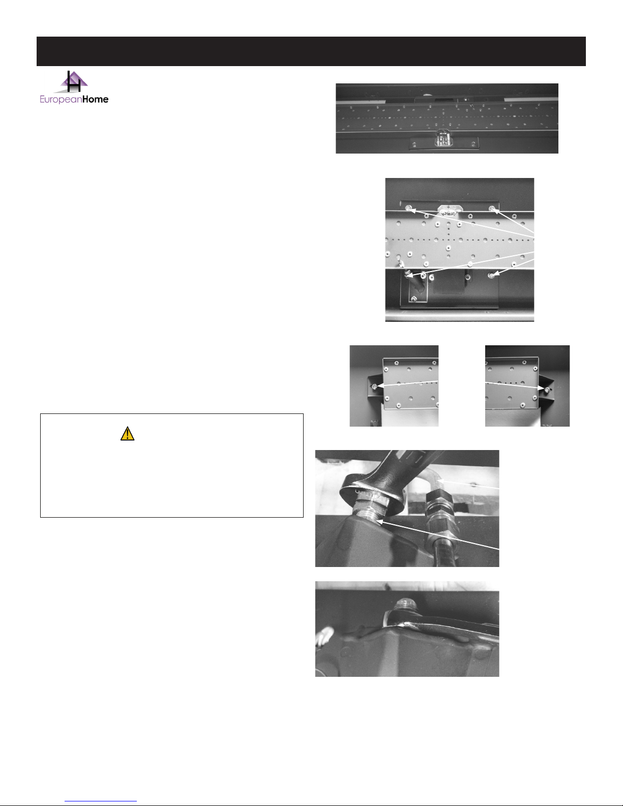
APPENDIX THREE
LP (PROPANE) CONVERSION
Bidore 140, Modore 140, Trisore 140 and all Lucius
APPLICABLE MODELS
CONTENTS
This LP conversion kit contains these instructions plus the
following:
• one Pilot Orice (stamped 27)
• one Main Burner Orice (stamped 380)
TOOLS REQUIRED
Converting your replace to LP gas requires the following tools:
- an 8mm box/open end wrench
- a 10mm box/open end wrench
- a 15mm box/open end wrench
- a 17mm box/open end wrench
- Phillips screwdriver
- a pair of small needle nose pliers
- a bright work light
Figure 1.
Holddown
Bolts
Figure 2.
Holddown
Bolts
WARNING!
This conversion must be done by a licensed
plumber or gastter.
Turn o the gas supply before proceeding.
Begin by reading all instructions thoroughly.
INSTALLATION
Before you begin, be certain there is enough slack in the gas
control lineset to allow the burner to lift up at least 8”.
Step 1: Remove the long glass panel and carefully store it.
Step 2: Remove all of the re media.
Step 3: Remove hearth (bottom) panel by lifting it up and out.
Figure 1 shows panel removed.
Step 4: Remove the 6 burner holddown bolts See Figures 2
through 4.
Step 5: Carefully lift the burner o the gasket and, taking care
to not damage the lineset, lay the burner securely, upside
down, in front of the replace.
Figure 3. Figure 4.
Main
Burner
Inlet Tube
Main Burner
Orice
Figure 5.
Figure 6.
Step 6: Using a 17mm wrench, remove the main burner inlet
tube from the main burner orice. See Figure 5.
Step 7: Using a 15mm wrench, remove the main burner orice
from the main burner. See Figure 6.
Element4 Gas Fireplaces EuropeanHome.com
63
Page 64
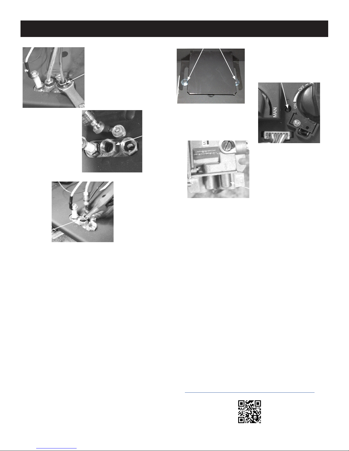
Thermocouple
Fastening
Nut
APPENDIX THREE
Shutter Nuts
Adjustment Screw
Figure 7.
Pilot Burner
Figure 8.
Pilot Orice
Figure 9.
Step 8: Install the main burner LP orice (stamped 380) into
the main burner and tighten.
Figure 10.
Figure 11.
Manifold Pressure Test Port
Figure 12.
Step 15: Place the main burner back into position and fasten
with the six burner bolts.
Step 16: Using a 10mm wrench, loosen the two shutter nuts
and slide the shutter completely open. See Figure 10.
Step 17: Remove cap to gain access to the pressure regulator
adjustment screw. See Figure 11.
Step 9: Install the main burner inlet tube onto the main burner
orice and tighten.
Step 10: Using a 10mm wrench, remove the thermocouple
fastening nut and slide the thermocouple out of the thermocouple tower. See Figure 7.
Step 11: Using a 10mm wrench, remove the pilot burner inlet
tube from the pilot burner. See Figure 8.
Step 12: Remove the pilot burner orice and replace it with
the LP orice (stamped 27) provided. Take care to observe the
proper orientation. See Figure 9.
Step 13: Connect the pilot burner inlet tube and tighten the
nut.
Step 14: Insert the thermocouple fully into the thermocouple
tower and tighten the nut.
Element4 Gas Fireplaces EuropeanHome.com
Step 18: Connect LP gas supply to replace. Loosen the
screw inside the manifold pressure test port and connect the
manometer to the port. See Figure 12.
Step 19: Turn on the replace and set the ames to high. While
turning the pressure regulator screw, adjust the manifold
pressure to 10.8” w.c.
Step 20: Turn o the replace, remove the manometer and
close the test port screw.
Step 21: Replace the hearth panel, the burner media and the
glass panel. Check for proper replace operation.
To see how to convert the gas on an Element4 replace,
please visit the link below.
WWW.EUROPEANHOME.COM/RESOURCES/VIDEOS/
64
Page 65
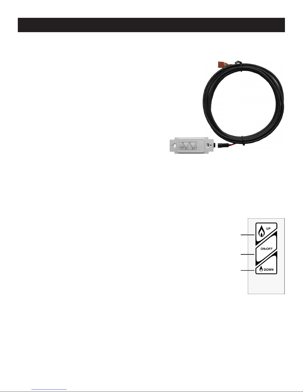
APPENDIX FOUR
INSTALLING AN OPTIONAL WALL SWITCH
see Figure 5.1
1. Install a single-gang electrical workbox (not supplied) at the
desired location - no more than 26 feet as the cable runs.
2. While keeping the black connector (A) inside the work box,
thread the black 4-wire cable through the workbox and bring
the red connector (B) to the location of the receiver.
3. Connect the black connector (A) to the wall switch, the red
connector (C) to the receiver.
4. Test for proper operation then screw the wall switchplate to
the workbox with the two screws provided and attach the
faceplate (included).
B
A
Figure 5.1
USING THE WALL SWITCH
see Figure 5.2
Note that, with the wall switch, you can turn the replace on and o and adjust the ames up
and down. The rear burner, however, can only be turned on/o with the remote control (model
applicable).
• Turn replace ON: Press the ON/OFF button until a short beep conrms the start sequence
has begun then release the button.
• Increase the ame height: Press and hold the UP button.
• Decrease the ame height: Press and hold the DOWN button.
• For ne adjustment tap the UP or DOWN button as necessary.
• Turn replace OFF: Press the ON/OFF button.
UP
ON/OFF
DOWN
Figure 5.2
Element4 Gas Fireplaces EuropeanHome.com
65
Page 66

INDEX
A
APPLIANCE RATINGS 7
AC ADAPTER SPECIFICATIONS 7
C
CERTIFICATION
Listing LabeL 8
Massachusetts 60
CLEARANCES
Drawings 16
Location 15
ManteLs 20
warM air outLet(s) 21
E
ELECTRIC
requireMents 22
ac aDapter specifications 7
ENCLOSING THE FIREPLACE 33
F
FIRE MEDIA
instaLLing the Logset 46
instaLLing the stones 47
FIRST FIRE 45
O
OPERATING THE FIREPLACE
test fi re 45
using the reMote controL 43
using the waLL switch 65
P
PARTS OF THE FIREPLACE 13
S
SAFETY INFORMATION 3
SAFETY SCREENS 48
SPECIFICATIONS
appLiance ratings 7
DiMensions - Lucius 140 rooM DiviDer 9
DiMensions - Lucius 140 tunneL 10
DiMensions - Lucius 140 1/3 11
DiMensions - Lucius 140 2/3 12
V
vENTING
configuration 23
horizontaL terMinations 25
verticaL terMi nations 28
restrictors 32
G
GAS
converting to Lp 63
instaLLing the gas Line 22
pressures 7
L
LISTING LABEL 8
LP (PROPANE) CONvERSION 63
M
MAINTENANCE
burner 57
piLot 57
therMocoupLes 58
vent 58
MANTELS 20
N
NON-COMBUSTIBLE MATERIALS
approveD Manufacturers anD proDucts 33
MiniMuM cLearances 15
W
WARRANTY 59
Element4 Gas Fireplaces EuropeanHome.com
66
Page 67

NOTES
Element4 Gas Fireplaces EuropeanHome.com
67
Page 68

Imported and distributed in North America by:
EUROPEAN HOME
a division of Europa Ja, Inc.
376 Washington Street
Suite 203
Malden, MA 02148
www.europeanhome.com
Element4 Gas Fireplaces EuropeanHome.com
68
IGE411-151002
 Loading...