

Page 1
INSTALLATION MANUAL
For all “Element4 - Electric Fires”
LEAVE THESE INSTRUCTIONS WITH THE DEVICE
Page 2

INSTALLATION MANUAL
2
Page 3

INSTALLATION MANUAL
Content
1 CE statement 4
2 Waranty 4
3 Important safety information 5
4 Connection 5
5 Installation method 6
6 Hollow wall installation method 6
7 The One-Box System 8
8 Decorating the replace 10
9 User Instructions 10
10 Troubleshooting 11
3
Page 4

INSTALLATION MANUAL
1 CE statement
We hereby declare that the design and construction of the
Element4 electric appliances are complying to the essential
demands and regulations for electric products.
Product:
• Electric fire
Models:
• 50e
• 80He
• 80XHe
• 100e
• 150e
• 150He
• 180e
All Element4 Electric fires meet the requirements of the EC
Directives. These directives have been met by compliance with
the following standard
• EN 55014-1:2006 + A2:2011
• EN 55014-2:2015
• EN 61000-3-2:2014
• EN 61000-3-3:2013
• EN 60335-1:2012 + A1:2014
• EN 60335-2-30:2009+A11:2012
This declaration loses its validity when changes to the device
are made without the written permission by Element4. You
can ask for a copy of the test certificates of all models via
our general e-mail adress, which is found on the back of this
manual.
2 Waranty
Should this device show defects within 24 months of purchase
due to shortcomings in construction, material or workmanship,
the product will be repaired free of charge under the following
conditions:
It is the responsibility of the buyer to prove that the device is
covered by the warranty, e.g. with a proof of purchase.
Any guarantee will lapse if
• unauthorized repairs or modifications have been made to
the electric fireplace
• in the event of an accident, misuse or damage caused by
an incorrect installation
• damage occurred during transport to or from the
• repairer, and changed or missing serial numbers.
Parts replaced under this warranty will become our property.
The company is not liable for consequential damage or any
other damage arising from or related to this electric fireplace.
This warranty does not apply to heating elements, lamps or
fuses. Service visits where no errors are found and installation
errors are not covered by the manufacturer’s warranty.
In this case, the maintenance technician employed by us will
charge you for the service visit.
This guarantee is an addition to and does not aect the legal
rights of the buyer as a consumer.
J. Kempers
CEO
Replacement plug
Caution: when removing the molded plug and connection to
a fused tap through a unqualified person, the guarantee will
lapse.
4
Page 5

INSTALLATION MANUAL
3 Important safety information
Please read these instructions before installation or use and
keep this booklet handy for future reference
This appliance can be used by children aged from 8 years and
above and persons with reduced physical, sensory or mental
capabilities or lack of experience and knowledge if they have
been given supervision or instruction concerning use of the
appliance in a safe way and understand the hazards involved.
Children shall not play with the appliance. Cleaning and user
maintenance shall not be made by children without
supervision
The instructions shall state that the heater must not be located
immediately below a socket outlet.
WARNING
in order to avoid overheating, do not cover the heater.
Children of less than 3 years should be kept away unless
continuously supervised
Children aged from 3 years and less than 8 years shall only
switch on/o the appliance provided that it has been placed
or installed in its intended normal operating position and they
have been given supervision or instruction concerning use
of the appliance in a safe way and understand the hazards
involved. Children aged from 3 years and less than 8 years shall
not plug in, regulate and clean the appliance or perform user
maintenance.
4 Connection
This appliance must only be connected to a 230/240 Volts AC
50Hz supply. Before connecting the fire, check that the supply
voltage is the same as stated on the fire.
This appliance must only be used on a AC supply, fuse rating
13Amp. The wires in the mains lead are coloured in accordance
with a standard UK supply, these being:
• GREEN/YELLOW – EARTH
• BLUE – NEUTRAL
• BROWN – LIVE
As the colours of the mains lead of this appliance may not
match the coloured markings used to identify the terminals in a
plug, please observe the following
• The green and yellow wire must be connected to the
terminal in the plug which is marked with the letter E or
Earth symbol.
• The blue wire must be connected to the terminal in the
plug which is marked with the letter N.
• The brown wire must be connected to the terminal in the
plug marked with the letter L.
• Replace fuses only with fuses of the correct size and rating.
Maintenance
Maintenance to this device may only be done by a qualified
professional. It is adviced to maintain your fire at least once
every 12 months.
CAUTION
Some parts of this product can become very hot and cause
burns. Particular attention has to be given where children and
vulnerable people are present
General Warnings:
• Never leave children unsupervised with an unguarded
heater.
• Never obstruct or cover the heater outlet.
• Never install or use this product where it may come in
contact with water i.e. a bathroom or wet room.
• Never use aerosols or steam cleaners near this product.
• Never route the electric cable near the heater outlet.
• Never route the electric cable under carpets or floor
coverings.
• Never install this product close to curtains or combustible
materials.
• Never use the heater to dry clothes or other objects.
• Never remove the fireplace surrounding without isolating
the electric supply.
WARMING:
Before reparation or maintenance check whether the fire is
unplugged.
4.1 Important electrical safety
This appliance must never be installed above or in front of a
fixed electric socket.
The electrical socket must be easily accessible to isolate the
supply during maintenance and cleaning.
This appliance is supplied with a two meter power lead, which
has a 13Amp moulded three pin plug to connect to a standard
230/240V plug socket.
This appliance must always be earthed. If in any doubt consult
a suitably competent person.
CAUTION
The LED light system shall be replaced by electrically
competent personnel only (LP – These cannot be user
replaceable since they will allow access to live parts)
NB: This fireplace may not be used as a primary heat source.
5
Page 6

INSTALLATION MANUAL
5 Installation method
Built in models
This product has been designed to be installed into a plaster
board, or existing masonry chimney breast.
Please seek advice from a professional, with reference to the
structural integrity of the installation site.
If the product is to be installed into a open chimney or flue, it is
important that the chimney/flue is blocked o to prevent any
up/down draughts and falling debris which could restrict
and alter the airflow to the product.
It is also important to ensure that the product has a minimum
internal clearance directly above and below the product of
50mm, this is to ensure that the product can circulate the
required airflow for the heater unit.
The product should never be sealed into a opening with the
use of silicones or adhesives as this can also alter the airflow
and hinder any further servicing of the product
Heating shut-off protection
This protection protects the product against damage.
6 Hollow wall installation method
In all Element4 fireplaces, a free space of 100mm at least 50mm
must be maintained immediately above and below the main
housing for good air circulation. (Failure to do so may cause
problems for the heating and flame function).
Each Element4 fireplace is supplied with one or more wall
mounting brackets.
Determine the height at which the finished Element4 fireplace
should be positioned in relation to the floor level.
Note:
The minimum distance to the floor is 300 mm
Attach the wall bracket to the wall, making sure that you use
the correct fasteners that match the respective wall - hollow or
solid.
Hang the Element4 fireplace on the bracket and secure it in
place with the wall bracket at the top of the fireplace.
Insert the plug of the IEC-compliant power cable into the IECcompliant socket and ensure that it is firmly pushed.
When the air circulation is impeded, the fire is switched o
automatically. This can happen with incorrect installation of
the fireplace, or blockages.
To reset the heating function:
• Remove the plug from the socket.
• Allow the product to cool.
• If the device has cooled down suiciently, remove any
blockages and check the installation.
Aer 10 minutes, the thermostat switch (trip protection) of the
heater is reset.
Note:
Both the eect fan and the heating fan produce a so sound
that is associated with normal operation of the stove.
Note:
Place the device near a suitable socket so that it can be
connected to the mains.
It is important that the outlet is located outside the installation
location so that the socket is easily accessible and the plug
can be disconnected from the stove aer installation.
Aer the fire is attached to the wall and connected to the
socket, the surround (the chimney) can be placed around it.
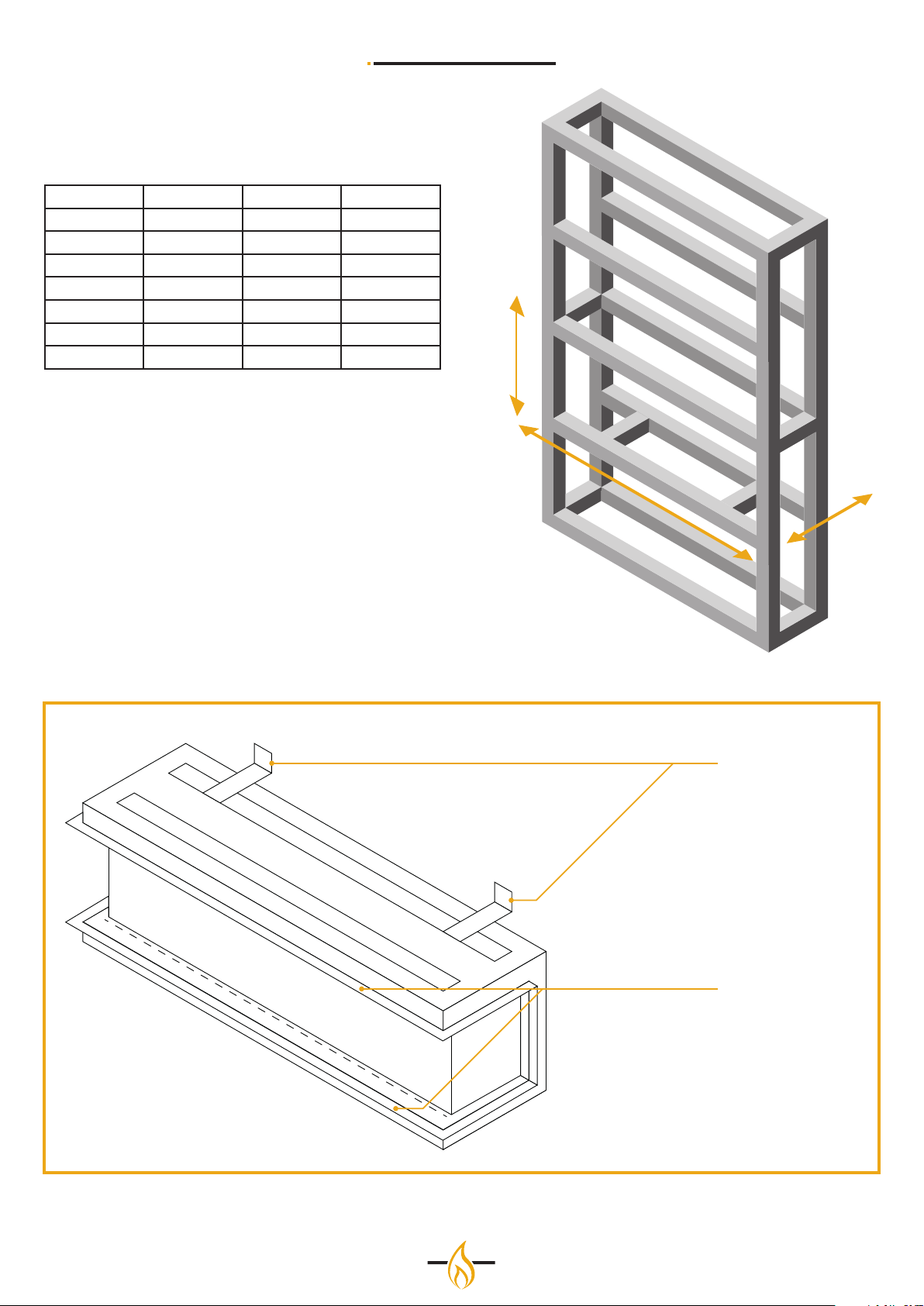
Construct the hollow installation space for the electric fire in
the desired dimensions. For minimum opening dimensions,
see Figure 1 and Table 1.It is important that you take into
account the finished front when determining the depth of the
frame construction.
It is important that a header/lintel is also placed at the desired
height, so that the weight of the wall made will not come to rest
on the appliance.
Make the cut in the plasterboard / finishing plate and install the
fireplace, making sure that the plaster board edges connect to
the inside of the cut in the plate.
CAUTION
In order to avoid a hazard due to inadvertent resetting of the
thermal cut-out, this appliance must not be supplied through
an external switching device, such as a timer, or connected to a
circuit that is regularly switched on and o by the utility.
6
Page 7
INSTALLATION MANUAL
D
The definite opening dimensions aer installation are in the
table below
Model Width (mm) Depth (mm) Height (mm)
50 495 305 610
80H 802 305 590
80XH 838.5 316 1209
100 1003 305 355
150 1505 305 355
150H 1538 316 808
180 1750 305 410
H
B
Wall Brackets
Plaster board edges
7
Page 8
7 The One-Box System
INSTALLATION MANUAL
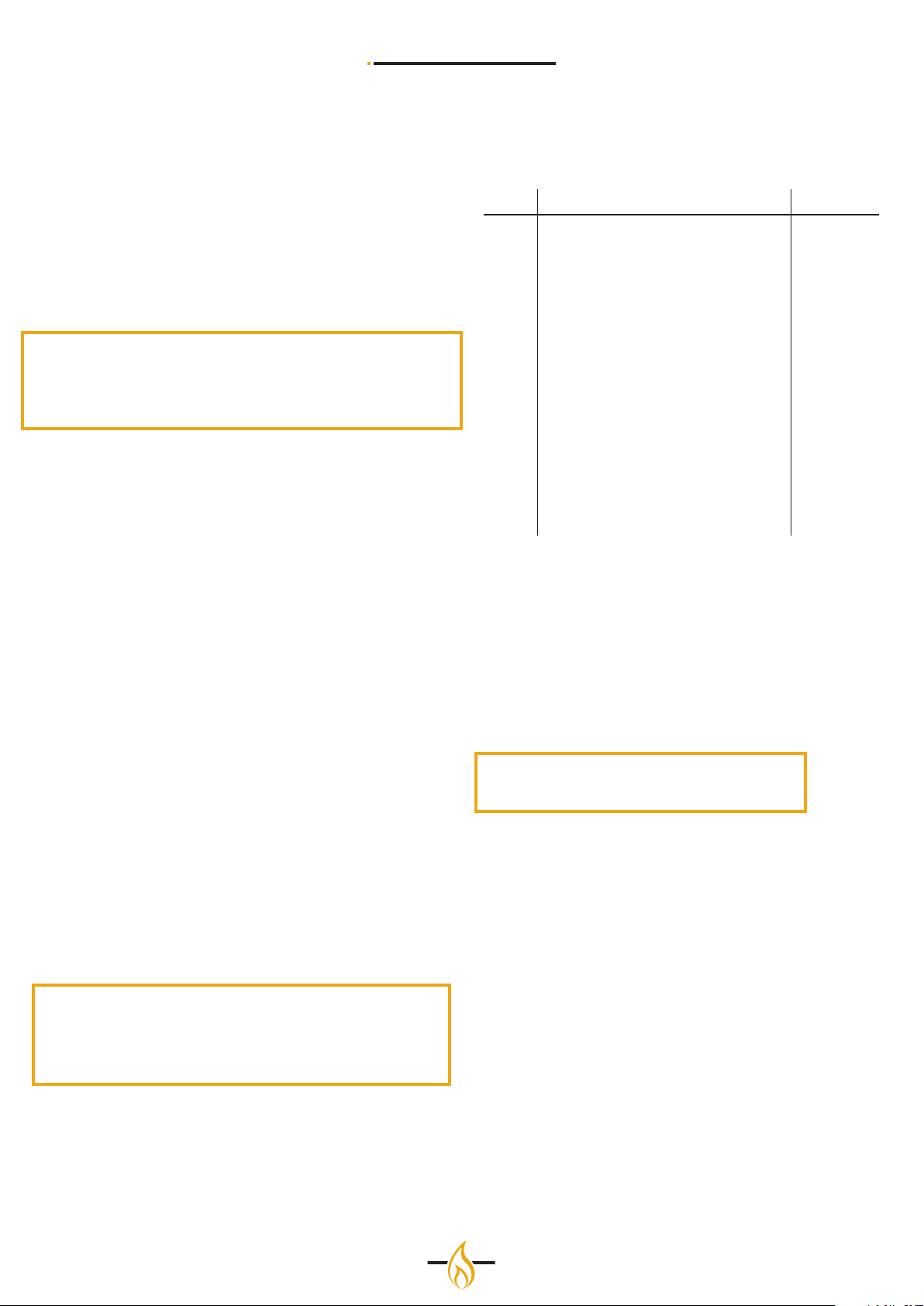
Every Element4 electrical appliance is delivered to the
customer according to the so-called one-box system. This
means that the customer can choose from four configurations
per fireplace type, depending on which sides of the fireplace
have glass or not. These four models are respectively the front
model, two corner models and a three-sided model.
This chapter explains the various steps with which the
customer can put together the desired configuration. The
fireplace is supplied as a three-sided model as standard.
Please note:
Check for the possible conversion of your fireplace first the
contents of the box.
In the table on the right and on the next page see all the parts
which are supplied in the box.
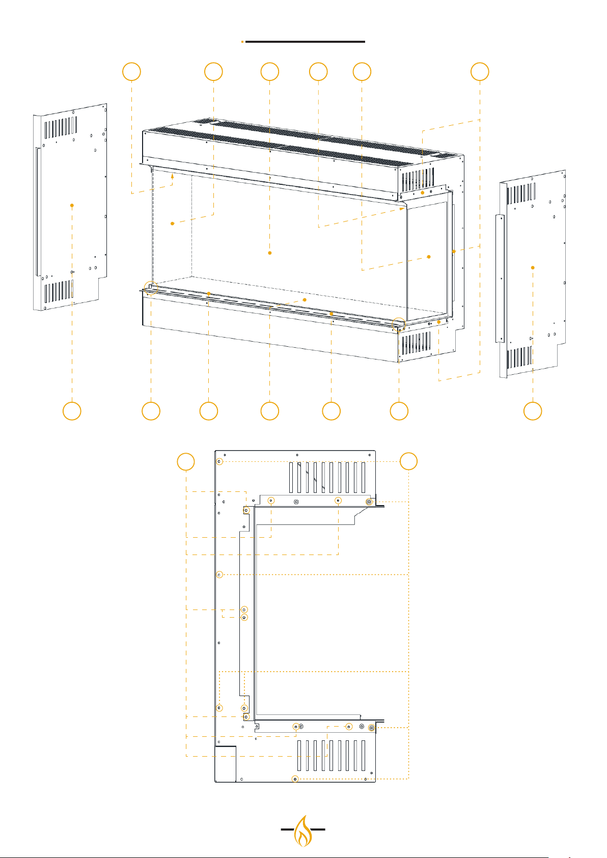
Part List
Make sure the following parts are included in the box.
ITEM DESCRIPTION Quantity
1 Side glass 2 o
2 Front glass 1 o
3 Plaster kit (3 o le side, 3 o right side) 6 o
4 Main housing 1 o
5 Front glass bottom support 1 o
6 Front glass bottom retainer 1 o
7 Front glass bottom retainer fixings 2 o
8 Fuel bed 1 o
9 Side glass top retainer (internal) 2 o
10 Side glass top retainer (internal) fixings 4 o
11 Plaster kit fixings 16 o
12 In-fill side piece fixings 16 o
13 In-fill right side 1 o
14 In-fill le side 1 o
Conversion steps
Step 1;
Removal of the front glass (item 2)
Remove the 2 o fixings (item 7) that secure the front glass
bottom retainer (item 6) to the fuel bed (item 8).
Li o the front glass retainer (item 7) and using the glass
suckers supplied (not shown) carefully remove the front glass
(item 2).
Step 2;
Removal of the side glass (item 1)
Remove the 2 o side glass top retainer brackets (item 9) by
taking out the 4 o fixings (item 10). 2 o on each bracket.
NOTE: If one wishes to install a corner model of the Electric the
steps need only be executed for the corner that is not supposed
to stay glass.
Carefully tilt the side glass inwards at the top and li it away
from unit.
Step 3;
Removal of the plaster kit (item 3)
Remove the plaster kit fixings (item 11) using a phillips screw
driver (not supplied)
Note: Ensure to keep fixings for future reference.
Remove the plaster kit (item 3) from both sides of the unit.
Step 4;
Fitting in the in-fill sides (item 13 and item 14)
Remove the In-fill side fixings (item 12)
Place the in-fill sides over the existing side pieces
Using the in-fill side fixings (item 12) together with the plaster
kit fixings (item 11) that were removed in the previous step
secure the le and right in-fill sides (item 13 and 14) to the unit.
8
Page 9
INSTALLATION MANUAL
19 1102 3
11
85 6 7714 13
12
9
Page 10
INSTALLATION MANUAL
8 Decorating the replace
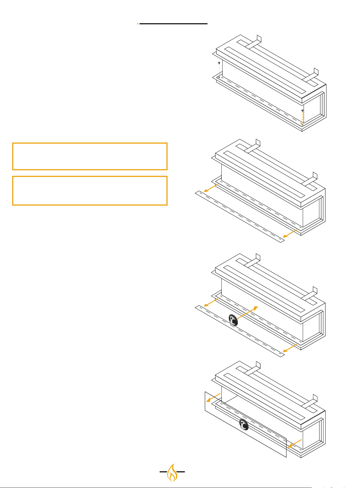
Removing glass front side
Follow the next steps for temoving the glass front window and
place the decorative logset.
1. Remove the two screws located in the bottom glass
retaining bar.
2. Remove the bottom glas retaining bar.
3. Remove the glass by pulling the second retaining bar
away from the body of the fire, ensure that the glass is
supported at all times.
Suction cup
A suction cup is provided to help aid this step. Please note the
suction cup is not to hold the full weight of the glass.
Tip
It is recommended with the 150e and 180e models to carry out
these steps with two persons.
Step 1
4. Place the log set as stated below and replace the glass in
reversed order of step 1 to 3.
Placing the logset
Every models is deliverd standard with a European logset. The
style and size of the set varies between models.
The logs can be arranged to personal preference and o not
influence the flames or the proper functioning of the fire.
9 User Instructions
The Element4 electric fires can be used with the Element4
Electric fire application available on Android and iOS.
For a full instruction on how to use your electric fires we refer
you to the user manual.
Step 2
Step 3
10
Step 4
Page 11

INSTALLATION MANUAL
10 Troubleshooting
Problem Possible Cause Solution
Flames not working correctly Ribbons are statically connected to glass. Spray some anti-static spray beneath the
tray.
Installation airflow restricted. Check the correct aperture has
been adhered to when installing—
Recommended clearance is 100mm.
Blower clogged. Fan requires cleaning out.
Slow fan. Fan requires cleaning out. If problem
persists, replacement fan may be required.
Heater blowing cold Possible installation gaps/Chimney not
adequately blocked o.
Fan clogged. Heater fan requires cleaning out
Faulty element. Replace element
Slow fan. Check fan placement. If problem persists
Noisy Heater Fan unbalanced. Adjust fan to stop catching on the case.
Fan catching on housing. Adjust fan to stop catching on the case
Fan clogged. Fan requires cleaning out. If problem
Fan has come loose. Tighten fan cradle or screws holding fan
Heater coming on randomly Timer has been accidentally set. Double check timer settings.
Thermostat faulty. Replace PCB.
LED streaking LED dropped down. LED needs to be re-stuck into place.
Log positioning. Change log positioning to hide any direct
Heater cutting out Build up of hot air triggering heater cut-
out unit.
Chimney may not be fully blocked.
Correct aperture has not been adhered
to—100mm
replacement fan may be required.
If problem persists replacement fan unit
maybe required.
persists a replacement fan may be
required.
onto fan cradle.
view of LED strip.
Ensure the appliance has the required
aperture for air to circulate and prevent
build-up. Recommended 100mm
11
Page 12

ELEMENT 4 B.V.
Paxtonstraat 23
8013 RP Zwolle
The Netherlands
[email protected]
www.element4.nl
20/01/20
 Loading...