

Page 1
HI-DEFINITION A/V ROUTING SYSTEM
Version 1.0
Please read this user manual carefully before using this product.
Failure to understand operation procedures may result in injury.
Page 2

C O N TE N TS
01
Brief Introduction
Product Features
Technical Specications
Packing List
Installation and Use
Meanings Of Indicator Statuses
Specications
FCC Information
Contents
Structure
FAQs
Back cover
2
2
4
3
4
7
10
11
12
Page 3

02
Brief Introduction
Product Features
Thank you for choosing our ELEMENT8085 high-denition
(HD) wireless audio/video (AV) transmission system devices. The
device can be wirelessly connected from an HD source device to
an HD display device such as TV, projector, HD disc player, game
machine, recorder, and set-top-box at home. With the device, you
can enjoy HD video anywhere at home. In addition, you are
relieved from the cost and hassle of running cables to complete
your installation.
Instant wireless HD AV transmission;
Transmission range indoors 30m;
Supports video HDMI interface at a maximum of 1080P 60 Hz;
Supports HDMI1.3 and HDCP1.2 protocols;
Supports EDID function;
Supports CEC function (for the receiving and display devices);
Supports IR extension transmission function;
Transmission power 12 dBm;
Supports point-to-point transmission function which can currently be
expanded to point to multi-point or multi-point to multi-point
transmission function;
Supports AES128-bit image encryption function;
Supports reverse back-transmission channel at the maximum
rate of 100 kbs;
Supports OSD display;
Supports WHDI 1.0 specication.
Page 4
03
RF communication system
Modulation mode
Maximum transmission power
MI MO
OFDM
12dBm
Technical Specications
* The working frequency band may vary with the relevant laws in
dierent countries or regions.
Video formats supported
TV 1080p, 1080i, 720p, 576p,480p
PC: VGA(640X480), SVGA(800X600),
XGA(1024X768), SXGA(1280X1024)
PCM,DTS, DOCBY DIGITAL
<1 ms
Built-in
5.1~5.9GHz
38KHz
100-240V AC mains, 5V 2A DC power
O
-10~50 C
Audio formats supported
Image transmission distance
Image delay
Transmission/receiving
antenna mode
Operating frequency
IR carrier modulation
frequency supported
Operating power supply
Storage temperature
30 m
O
-20~80 C
Storage temperature
Page 5
04
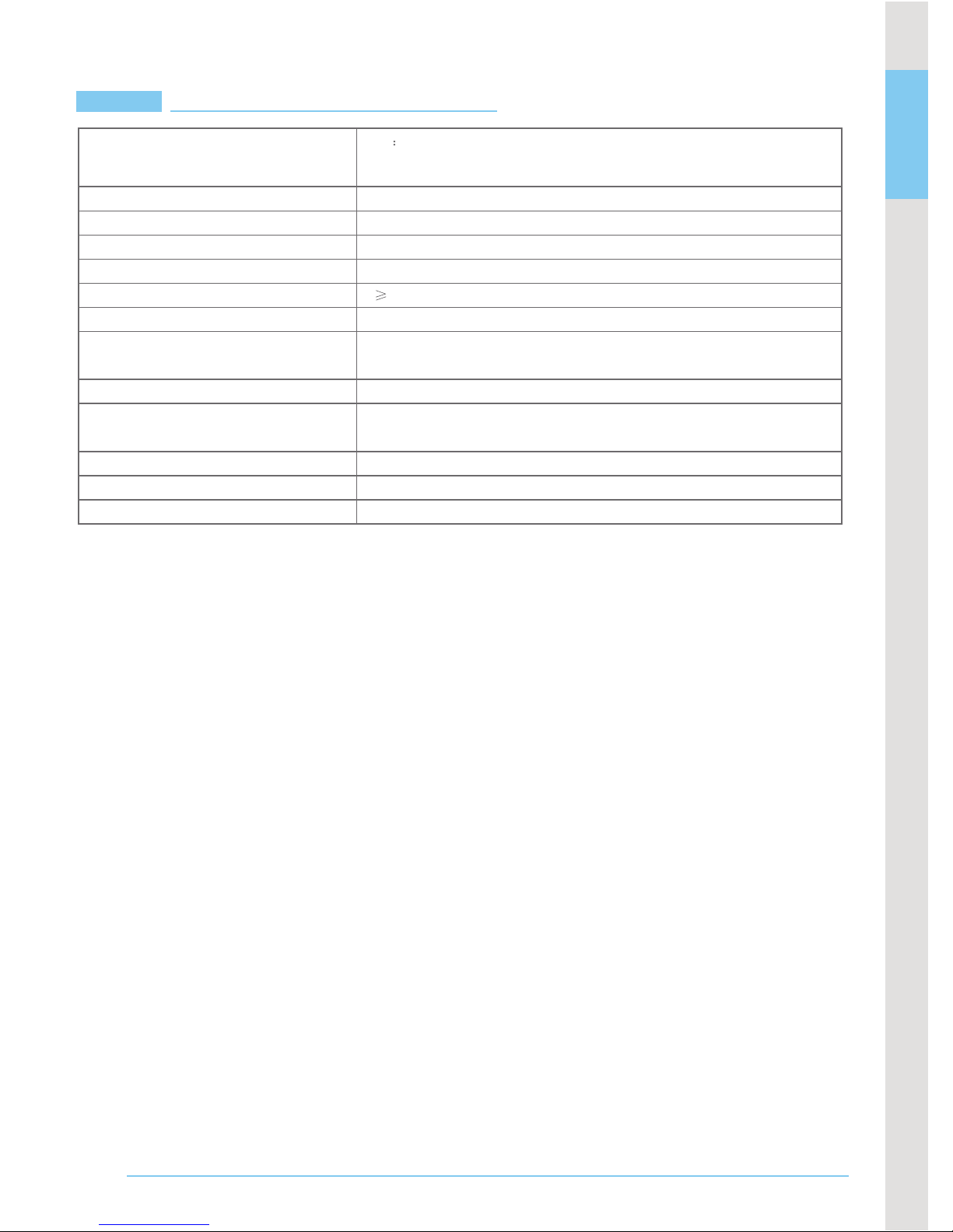
HD wireless video
transmitter x 1
HD wireless video
receiver x 1
Base x 2
IR remote extension
connector x 1
Power supply x 2
Packing List
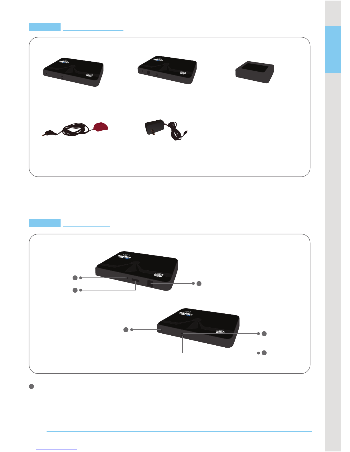
Structure
Transmitter
2
3
1
6
4
5
1
Power Input Port
This port is connected to the 5V/2A power adapter which is
5.5mm in diameter and positive outside and nega tive inside.
Page 6

05
4
5
6
3
2
Connector
HDMI Input Port
This port is connected to a video cable supporting the HDMI1.3
protocol.
Output Interface for IR Remote Signals
This interface is connected to an IR extension cable for extending
the IR remote receiving function.
Wireless Network Status Indicator
If this indicator turns green after the power supply is connected,
it indicates that wireless network connection is made successfully;
if this indicator is not ON, it indicates that wireless network
connection fails to be made; if this indicator ashes, it indicates
that the device is faulty.
Video Status Indicator
If this indicator turns green after an HDMI cable is connected,
it indicates that video connection is made successfully; if this
indicator is not ON, it indica tes that video connection fails to
be made.
Code Key
This key functions to: 1. Enhance transmission distance: When
the distance between a transmitter and a receiver exceeds the
transmission distance, press this key on the transmitter or
receiver to enhance the transmission distance. The picture
quality, however, deteriorates; 2. Enable the code matching
function: Press this key on the transmitter and the receiver for
3 seconds at the same time, the codes of the machines will be
matched again automatically.
2
3
1
4
5
6
Page 7

06
2
1
3
4
5
6
Power Input Port
This port is connected to the 5V/2A power adapter which is
5.5mm in diameter and positive outside and nega tive inside.
HDMI input port
This port is connected to a video cable
supporting the HDMI1.3
protocol.
Output Interface for IR Remote Signals
This interface is connected to an IR extension
cable for extending
the IR remote receiving function.
Wireless Network Status Indicator
If this indicator turns green after the power
supply is connected,
it indicates that wireless network connection is made
successfully;
if this indicator is not ON, it indicates that wireless network
connection fails to be made; if this indicator ashes, it indicates
that the device is faulty.
Video Status Indicator
If this indicator turns green after an HDMI cable is connected,
it indicates that video connection is made successfully; if this
indicator is not ON, it indicates that video connection f ails to
be made.
Code Key
This key functions to: 1. Enhance transmission distance: When
the distance between a transmitter and a receiver exceeds the
transmission distance, press this key on the transmitter or
receiver to enhance the transmission distance. The picture
quality, however, deteriorates; 2. Enable the code matching
function: Press this key on the transmitter and the receiver for
3 seconds at the same time, the codes of the machines will be
matched again automatically.
IR Remote Receiving Window
Its function is the same as that of the remote receiving window
on a set-top-box. The video source can be controlled remotely
by pointing at this window.
Page 8

07
Installation and Use
* It is recommended to place a transmitter and a receiver verticall
or horizontally at the same time during installation.
If the transmitter and the receiver are placed across each other, for
example the transmitter is put vertically and the receiver is
placed horizontally, the image transmission distance may be aected.
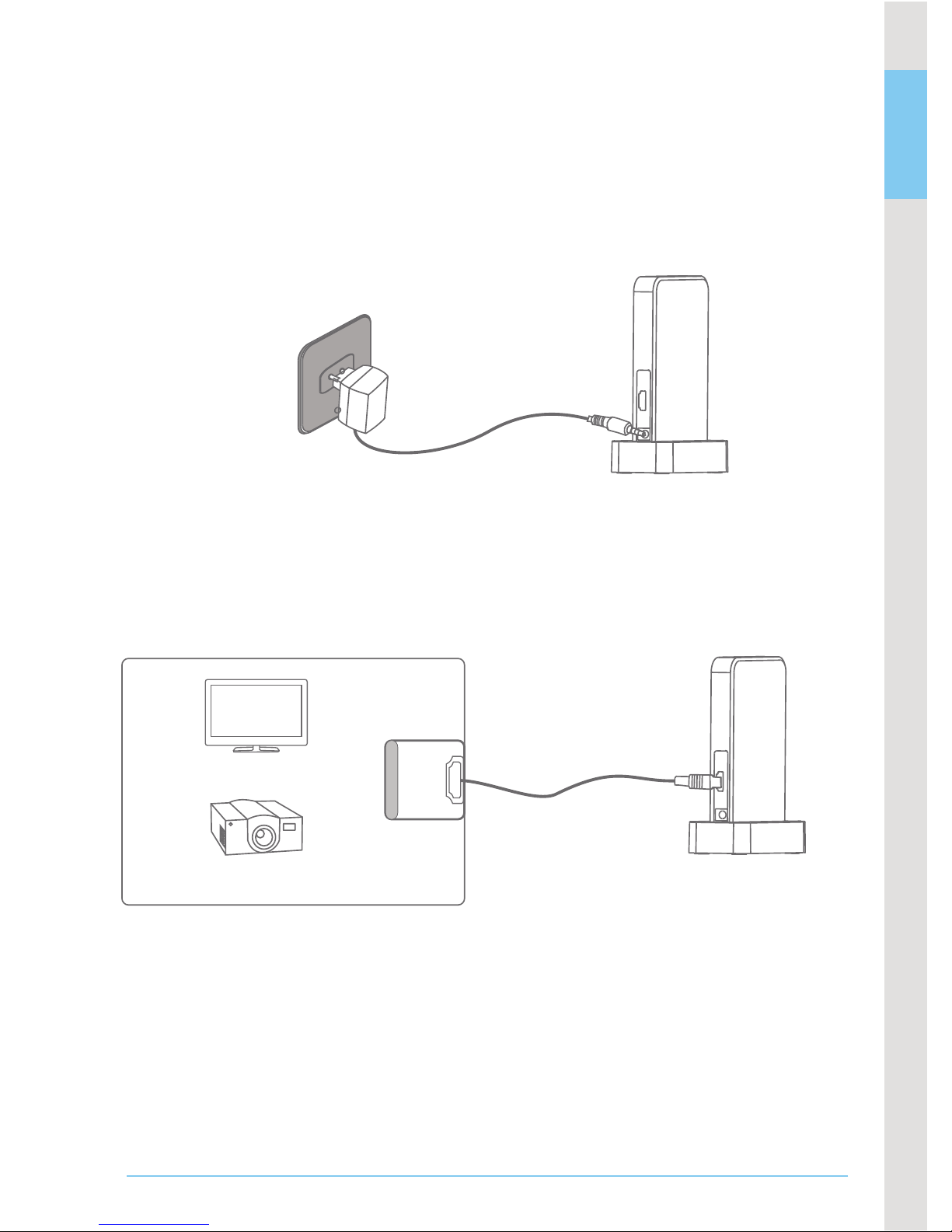
Installation for Transmitter
1. Install the transmitter on a base and then place the transmitter
in a suitable position beside an HD video source.
Note:
* Put the antenna end upward.
* Do not place any article on the transmitter or beside it to avoid
aecting the transmission distance and image eect.
2. The wireless network status indicator is ON after the transmitter
power supply is connected and wireless network connection i
made successfully.
3. The video status indicator is ON after the transmitter is connected
to the video output socket of the HD source with an HD AV cable.
Page 9

08
* Any video source with the HDMI video output interface can be connected.
4. Connect the IR remote extension connector to the IR remote
signal output hole of the transmitter.
Installation and Use for Receiver
1. Install the receiver on another base and place the receiver
beside an HD display device in another room.
Note:
* Put the antenna end upward.
* It is not recommended that you place any article on the receiver
or beside it to avoid aecting the receiving distance and image
eect.
HD MI O UT
DVD player
Set-top-box
Game machine
POO3
Page 10
09
* The transmission distance between the transmitter and the
receiver is 30 meters at most. If signals are obtained by
penetrating a wall, the transmission distance and may be aected.
2. The wireless network status indicator is ON after the receiver
power supply is connected and wireless network connection is made successfully.
3.3. Connect the receiver to the HD display device with a standard
HD AV cable. The video status indicator on the receiver is ON after
video connection is made successfully. Images appear on the display device.
4. The video source can be controlled remotely by pointing the
remote control at the IR receiving window on the receiver.
* Any display device with the HDMI video input Interface can be connected.
Note: This product matches only with
an IR remote control in the 38 KHz carrier modulation mode.
HD MI I N
HD projector
HD TV
Page 11

10
Meanings of Indicator Statuses
status indicator
Ind i cator
Indicator status
Working status
The receiver is connected
successfully in the wireless mode
The receiver fails to be connected
in the wireless mode
The device is abnormal
The display device is connected successfully
The display device fails to be connected
The tr ansmitter is c onnected
successfully in the wireless mode
The transmitter fails to be
connected in the wireless mode
The device is abnormal
The video source is connected successfully
The video source fails to be connected
Green on
O
Flash rapidly
Green on
O
Green on
O
Flash rapidly
Green on
O
Wireless connection
status indicator
(tr a n sm it t er )
Wireless connection
(re c e iv er )
Video indicator
(tr a n s mi t te r )
Video indicator
(re c e i ve r )
Page 12

11
Frequency Stability
5.1~5.9GHz
4PPM
2A 10%
-75dBm
5V
DC
148 x 97 x 18 (mm)
440g (including the base)
15~85%RH
O O
-10 C~50 C
40MHz
30m
System Latency
1ms
Sending/receiving channel 4 channels for sending/1channel for receiving
HD video protocol
HDMI 1.3
HD video encryption protocol
HDCP 1.2
RF communication system
Modulation mode
MI MO
OFDM
5.1~5.9GHz
4PPM
-65dBm
148 x 97 x 18 (mm)
436g (including the base)
40MHz
15dBm
30m
1ms
HDMI 1.3
HDCP 1.2
5V
DC
2A 10%
O O
-20 C~80 C
12dBm
SPECIFICATIONS
* All the specications are subject to minor change without prior
notice.
Transmission Frequency
Transmission Power
Bandwidth
Power Supply
Consumption Current
Unobstructed Eective Range
Dimensions (W x D x H)
Approx. Weight
Receiving Frequency
Receiving Sensitivity
Operating Temperature
Operating Humidity
Bandwidth
Transmission Power
Receiving Sensitivity
Unobstructed Eective Range
Power Supply
Consumption Current
Dimensions (W x D x H)
Approx. Weight
Frequency stability
HD video protocol
HD video encryption protocol
Storage Temperature
System latency
Sending/receiving channel 1channel for sending/4 channels for receiving
Tr a ns mit t erR ec eiver
Page 13

12
Trobleshooting
Symptom
Possible Reasons/Solutions
Why no images aredisplayed
on TV afterthe transmitter and
receiver are poweredon?
Why are the network
connection status
in di c a t o rs on the transmitter
and receiver not ON after b oth
devices are powered on for a
long period of time?
Why is the network
connection status indicator not
ON after I wait for a long period of
time although the transmitter
is near the receiver?
Both the transmitter network
connection status indicator
and video connection status
indicator are ON, but the video
connection status indicator is not
ON an d no images appear on
It may take 15-30 seconds for initiation and connection
after the transmitter and receiver are powered on.
Please wait patiently. If no images appear after 1 minute,
check whether the connection between the transmitter and
the player as well as the connection
between the receiver
and the TV are made properly. Further troubleshooting
can be made by referring to the conditions of device
status indicators.
Possibly the transmitter and receiver are too far
away or there are too many obstacles. Please
adjust the position of both devices.
Please conrm that whether codes of the
transmitter and the receiver match with each other. If
not, manually mat c h their codes. For the code
matching method, refer to relevantdescription in
this manual.
Please conrm whether the denition of images
output by the player meets the requirements for
this product. If not, Connect the player to the TV
directly. Adjust the denition to a suitable one,
and then connect the transmitter to the receiver.
Page 14

13
Why no signals are input to
the TV?
Images appear on TVnormally but
no voice is output.
Sound is output from the TV
normally but n o images
appear.
Why no images are o ut p u t
w h en th e transmitter is connected
to a blu-ray disc player and the
receiver is connected to a
PC display or a projector.
However, why images can be
output when another TV is connected?
What can I do when the network
connection status indicators on
the transmitter and the
rec e ive r as h rapidly and no
images appear on TV?
Please check whether the receiver is properly
connected to the TV. In addition, adjust the input
source of the TV to the HDMI interface connected to the
receiver.
Please conrm whether the player is muted or
whether the audio output iscongured correctly. Please
congure your player by referring to the audio
format supported by the product and then power on
the transmitter again.
Please check whether the connection between the
transmitter and the player as well as the connection
between the receiver and the TV are made
properly. Unplug and then plug the HDMI cable
connected between the transmitter and the
receiver.
The play requirements for blu-ray discs com pl y wi th
th e HD CP pr o to co l specications. Please conrm
whether your display device supports the HDCP protocol.
If not, the blu-ray disc cannot be played.
Power on the transmitter or the receiver again. If you power
on the device for many times and the fault cannot
be rectied, possibly the device is damaged. Please contact
the original manufacturer for repair.
Page 15

14
Cautions
FCC Information
Why there are so many noises or
mosaics on the image displayed
on TV?
Why cannot my player be controlled
remotely through the IR extension
function
This device complies with part 15 of the FCC Rules. Operation is subject to
the following two conditions:(1) This device may not cause harmful
interference. (2) This device must accept any interference received,
including interference that may cause undesired operation.Changes or
modications not expressly approved by the party responsible for
compliance could void the user's authority to operate the equipment.
The apparatus shall not be exposed to dripping or splashing and no objects lled
with liquids, such as vases, shall be placed on the apparatus. Turn o the
Camera/Monitor if the system is not in use. The adapter is used as the disconnect
device from the mains. The adapter shall remain readily operable. The
Camera/Monitor can only be completely disconnected from the mains by
unplugging the adapter. Do not cut the DC power cable of the apparatus to t with
Possibly the transmitter and receiver are too far
away or there are many obstacles. Please adjust
the position of both devices. In addition, to achieve
better receiving eect, it is recommended that you place
both devices vertically.
Please ensure that the IR remote connector is
correctly connected to the transmitter and this
connector is opposite the IR receiving window
of the player. In addition, this product supports
only the IR control in the 38 KHz mode.
Page 16
EU Environmental Protection
Waste electrical products should
not be
disposed of with household
waste. Please
recycle where
facilities exist. Check with
your
local authority or retailer for
recycling
advice.
 Loading...