

Elektror RE 14 F, RD 6 F, RD 64 F, RD 62 F, RD 74 F Operating And Assembly Instructions Manual
...
RD F
Elektror Förderventilatoren
Betriebs- und
Montageanleitung
DE
Elektror Conveying Blowers
Operating and
assembly
instructions
EN
RD 14 F, RE 14 F, RD 4 F, RE 4 F, RD 5 F, RD 6 F, RD 62 F, RD 64 F, RD 74 F, RD 82 F
Elektror airsystems gmbh
Hellmuth-Hirth-Strasse 2, D-73760 Ostfi ldern
Postfach 1252, D-73748 Ostfi ldern
Telefon +49 (0)711 31973-0
Telefax +49 (0)711 31973-5000
info@elektror.de
www.elektror.de
Betriebs- und Montageanleitung RD F www.elektror.de
DE
2
INHALT
1 ANGABEN ÜBER DIE MASCHINE
2 INFORMATIONEN ÜBER TRANSPORT,
HANDHABUNG UND LAGERUNG DER MASCHINE
3 INFORMATIONEN ÜBER DIE INBETRIEBNAHME
4 ANGABEN ZU BETRIEB UND VERWENDUNG
5 ANGABEN ZUR INSTANDHALTUNG
6 SICHERHEITSRELEVANTE INFORMATIONEN ÜBER
AUSSERBETRIEBNAHME UND ABBAU
7 HAFTUNG UND HAFTUNGSAUSSCHLUSS
8 EINBAUERKLÄRUNG NACH ANHANG II 1 B
9 EXPLOSIONSZEICHNUNG
10 ERSATZTEILLISTE
11 TECHNISCHE DATEN
12 ANGABEN GEMÄSS ERP DURCHFÜHRUNGS-
VER ORDNUNG 327/2011
Diese Betriebs- und Montageanleitung muss dem Bedienungs-, Wartungs- und Reinigungspersonal jederzeit zugänglich sein. Lesen Sie die vorliegende Betriebs- und
Montageanleitung vor Montage und Inbetriebnahme des
Ventilators sorgfältig durch.
Änderungen vorbehalten. Im Zweifelsfall ist eine Rücksprache mit dem Hersteller erforderlich. Diese Unterlage ist urheberrechtlich geschützt. Sie darf ohne unsere ausdrückliche
schriftliche Zustimmung Dritten nicht zugänglich gemacht
werden. Jede Form der Vervielfältigung oder Erfassung und
Speicherung in elektronischer Form ist untersagt.
1 ANGABEN ÜBER DIE MASCHINE
Bitte entnehmen Sie unsere Anschrift dem Deckblatt.
Entnehmen Sie den Gültigkeitsbereich dieser Betriebs- und
Montageanleitung bitte der enthaltenen Einbauerklärung
nach Anhang II 1 B.
Die auf Seite 20 dargestellten technischen Daten gelten für
die Serienausführung. Ihr Ventilator kann davon abweichen
(siehe Leistungsschild). In diesem Falle beachten Sie bitte
die mitgelieferten zusätzlich gemeinsam geltenden Unterlagen oder die dann geltende, eigene Betriebs- und Montageanleitung.
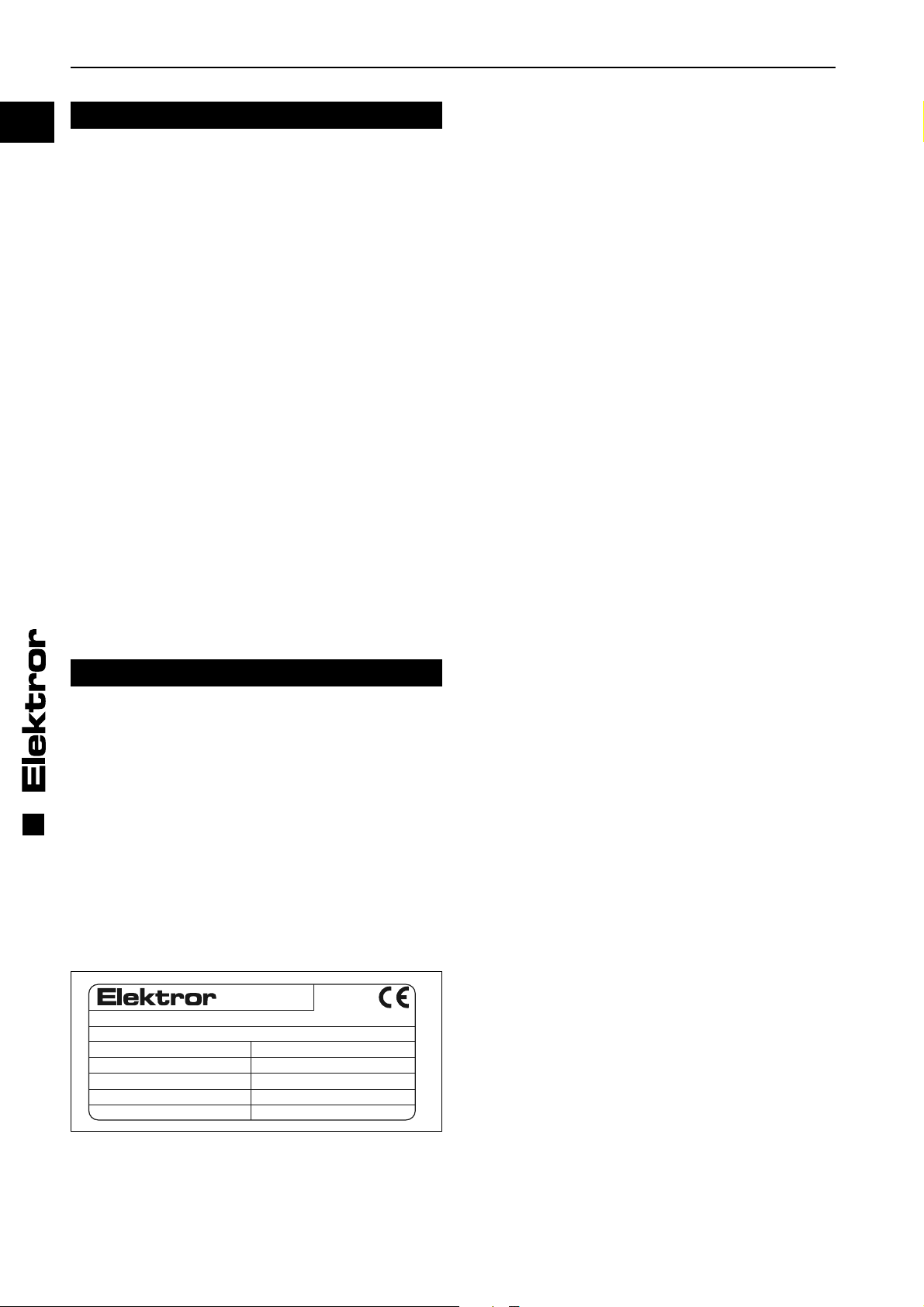
Leistungsschild
Für Anschluß, Wartung und Bestellung von Ersatzteilen sind
ausschließlich die Daten auf dem Leistungsschild maßgeblich. Dem Leistungsschild ist auch die Serien-Nummer des
Gerätes und dessen Herstellungsjahr zu entnehmen.
D-73760 Ostfildern
Germany
Typ Nr.
Mot. EN 60034-1 IP W-Kl.F
kW cos kW cos
Hz min
V V
A A
1.1 Bestimmungsgemäße Verwendung
Elektror-Förderventilatoren sind mit Laufrädern aus Stahlblech in geschweißter Ausführung und radial endenden
Schaufeln ausgerüstet.
Die Förderventilatoren eignen sich zum Fördern von Kunststoffgranulat, Kunststoffabfällen, sowie leichten Schüttgütern
-1
-1
min
Hz
aller Art. Stoffe oder Stoffgemische, von denen beim Betrieb
besondere Gefahren ausgehen können, dürfen nicht gefördert werden, z.B. brennbare Stäube, explosible Stoffe, chemisch instabile Stoffe oder Stoffgemische die miteinander
reagieren können. Die Förderventilatoren eignen sich nicht
zur Aufstellung in oder Förderung von explosionsfähiger Atmosphäre.
Der Einsatz für
• aggressive,
• abrasive,
• klebende,
• giftige,
• explosionsfähige oder
• sehr feuchte
Medien ist nicht zulässig.
Die maximale Temperatur des Fördermediums darf bei der
Serienausführung -20°C nicht unter- und +60°C nicht überschreiten.
Die maximale Umgebungstemperatur darf bei der Serienausführung -20°C nicht unter- und +60° C nicht überschreiten.
Der Ventilator ist nicht für die Aufstellung im Freien geeignet.
Der Ventilator ist grundsätzlich für S1-Betrieb (Dauerbetrieb)
ausgelegt. Davon abweichend sind maximal 30 Schaltungen
pro Stunde zulässig.
In der Serienausführung eignet sich der Ventilator nicht für
die Aufstellung in oder Förderung von explosionsfähiger Atmosphäre.
Sonderausführungen für den Einsatz außerhalb der oben
beschriebenen Anwendungen stehen auf Anfrage zur Verfügung. Umbau und Veränderungen des Ventilators sind nicht
zulässig. Bei Sondergeräten sind die Hinweise in den zusätzlich beigelegten Zusatzbetriebs- und Montageanleitungen zu
beachten und einzuhalten. Sie weichen in einzelnen Punkten
von dieser Betriebs- und Montageanleitung ab.
Elektror-Förderventilatoren zeichnen sich durch ein hohes
Maß an Betriebssicherheit aus. Da es sich bei Förderventilatoren um sehr leistungsfähige Maschinen handelt, sind
zur Vermeidung von Verletzungen, Beschädigungen von Sachen und der Maschine selbst, folgende Hinweise streng zu
beachten.
1.2 Mechanische Gefährdungen
Mechanische Gefährdungen sind an den Elektror-Ventilatoren dem Stand der Technik und den Anforderungen des
Sicherheits- und Gesundheitsschutzes entsprechend minimiert. Um handhabungsbedingte Restrisiken auszuschließen, empfehlen wir, in allen Lebensphasen des Gerätes geeignete Schutzausrüstung einzusetzen bzw. zu tragen (bitte
beachten Sie die Hinweise im Folgenden).
1.3 Gefährdung durch Hineinfassen und unerwarteten
Anlauf
Durch rotierende Teile besteht im Inneren des Gerätes im
Betrieb hohes Verletzungsrisiko. Setzen Sie das Gerät vor
dem Öffnen, Hineinfassen oder Einführen von Werkzeugen
in jedem Falle ausser Betrieb und warten Sie den Stillstand
aller bewegten Teile ab. Sichern Sie das Gerät während des
gesamten Zeitraumes zuverlässig gegen Wiederanlauf ab.
Stellen Sie sicher, dass während des gesamten Zeitraumes
kein Fördermedium oder z.B. Gemisch aus Fördermedium
und Luft in den Ventilator gelangt.
Stellen Sie ebenfalls sicher, dass keine Gefährdungssituation in Folge eines Wiederanlaufes nach einem Stillstand
entsteht, z.B. in Folge einer Energie-Unterbrechung oder
Blockade.
Zur Vermeidung von Verletzungen in Folge Hineinfassen
während des Betriebes, oder durch herausgeschleudertes
Fördermedium, müssen saug- und druckseitig während des
gesamten Betriebes Schlauch- oder Rohrleitungen fest angeschlossen sein.
016315 03.14/07

www.elektror.de Betriebs- und Montageanleitung RD F
1.4 Gewicht, sicherer Stand
Insbesondere während Transport und Aufstellung bestehen
Gefährdungen durch Umstürzen oder Herabfallen. Siehe 2.1
– Transport und Handhabung, sowie 3.1 – Aufstellen, Montage.
1.5 Ansaugwirkung
Ventilatoren erzeugen eine starke Saugwirkung.
Warnung!
Am Ansaugstutzen können Gegenstände, Kleidungsstücke und auch Haar angesaugt werden.
Verletzungsgefahr!
(Verletzungsgefahr durch Laufrad!).
Warnung!
Während des Betriebes nicht in der Nähe der Ansaugöffnung aufhalten! Wird der Ventilator ohne
saugseitigem Anschluß betrieben, ist zum Schutz
gegen Berührung eine Schlauch- oder Rohrleitung von mindestens 1 m Länge anzubauen.
1.6 Ausblaswirkung
Warnung!
Sehr starke Ausblaswirkung am Ausblasstutzen.
Angesaugte Gegenstände können mit hoher
Geschwindigkeit heraus geschleudert werden
(Verletzungsgefahr!).
Der Ventilator darf nie mit offenem Ausblasstutzen betrieben werden und muss daher mit einer
Schlauch- oder Rohrleitung von mindestens 1m
Länge versehen werden.
Nicht in den Ausblasstutzen hineingreifen!
1.9 Temperatur
Warnung!
Das Ventilatorgehäuse nimmt während des
Betriebs die Temperatur des Fördermediums an.
Wenn diese über +50°C liegt, muss der Ventilator
vom Betreiber vor direktem Berühren geschützt
werden (Verbrennungsgefahr!).
Besonders bei leistungsstärkeren Typen kann es bei der
Hindurchförderung von der Ansaug- auf die Ausblasseite zur
Erhöhung der Temperatur im geförderten Medium kommen.
Diese Temperaturdifferenz kann abhängig von den Betriebsbedingungen je nach Typ in einem Bereich von bis zu +20°C
liegen.
1.10 Motorschutzschaltung
Vor Inbetriebnahme des Ventilators muss der Antriebsmotor
mit einem Motorschutzschalter abgesichert werden (gilt nicht
für Frequenzumrichterbetriebene Geräte). Für Frequenzumrichterbetriebene Geräte ist der vorhandene Temperaturfühler (PTC-Kaltleiterfühler) oder Temperaturwächter (Öffnerkontakt) am Umrichter anzuschließen und auszuwerten.
1.11 Geräuschentwicklung
Die vom Ventilator abgestrahlten Geräusche sind nicht über
den gesamten Leistungsbereich konstant. Die abgestrahlten
Geräuschpegel bitte der Tabelle auf Seite 20 ff. entnehmen.
In bestimmten ungünstigen Einzelfällen ist eine Schalldämmung erforderlich (Messungen durch den Betreiber werden
empfohlen). Die Schalldämmung muss der Betreiber vornehmen, damit die gesetzlich zugelassenen Höchstwerte an
Arbeitsplätzen in der Umgebung des Ventilators nicht überschritten werden.
Schalldämmung jeglicher Art darf zu keiner unzulässigen
Erhöhung der Umgebungstemperatur über max. +40°C am
Antriebsmotor führen.
DE
1.7 Berührungsschutz, Schutz gegen Hineingreifen
Warnung!
Wird das Geräte indirekt nur als Druck- bzw. als
Saugförderer eingesetzt (auf der Ansaugseite
oder Ausblasseite befi ndet sich kein Rohr- bzw.
Schlauchanschluss) ist dieser entsprechend DIN
EN ISO 13857 mit einem Berührungsschutz zu
versehen. Dieser Berührungsschutz muss als
zusätzliches Ausrüstungsteil gesondert bestellt
werden.
1.8 Sicherheitshinweise zur Reinigung und Wartung
Warnung!
Reinigungs- und Wartungs-/Reparaturarbeiten
dürfen erst nach Stillstand des Laufrades vorgenommen werden. Elektrische Ein-/Ausschalter
als Wartungs/Reparaturschalter müssen abschließbar sein, oder so angeordnet werden,
dass bei Reinigungs- oder Reparaturarbeiten ein
unbefugtes Einschalten ausgeschlossen ist.
Das Förderlaufrad muss sich vor dem Öffnen im
Stillstand befi nden. Das Gerät muss bei Reini-
gungs-, Wartungs- oder Reparaturarbeiten zuverlässig stromlos bleiben und gegen Wiederanlauf /
unbeabsichtigten Anlauf gesichert sein.
016315 03.14/07
1.12 Elektrische Gefährdungen
Vor elektrischen Arbeiten jeglicher Art muss das Gerät in jedem Falle abgeschaltet und gegen Wiedereinschalten gesichert werden. Die Spannungsfreiheit ist zu prüfen.
1.13 Drehzahlen
Warnung!
Zur Vermeidung von Personenschäden darf die
auf dem Motorleistungsschild gestempelte
maximale Drehzahl keinesfalls überschritten werden. Bei einer Überschreitung droht die Gefahr
einer mechanischen Zerstörung des Ventilators.
Hierbei besteht Verletzungs- und Lebensgefahr!
Jedes Bauteil am Ventilator besitzt individuelle Eigenfrequenzen. Diese können durch bestimmte Drehzahlen des
Ventilators angeregt werden, was zu einem möglichen Resonanzbetrieb führt.
Die Ventilatoren sind so konstruiert, dass Resonanzen bei
konstanter Betriebsdrehzahl in der Regel nicht auftreten.
Wird der Ventilator an einem Frequenzumrichter betrieben,
könnte unter Umständen bei einer geänderten Drehzahl eine
Anregung erfolgen. Diese Umstände werden auch durch die
kundenindividuelle Einbausituation bzw. durch die lufttechnische Anbindung beeinfl usst.
Sollten diese Eigenfrequenzen innerhalb des Drehzahlbereiches des Ventilators liegen, dann müssen diese durch eine
entsprechende Parametrierung des Frequenzumrichters
ausgeschlossen werden.
3

Betriebs- und Montageanleitung RD F www.elektror.de
DE
4
2 INFORMATIONEN ÜBER TRANSPORT,
HANDHABUNG UND LAGERUNG DER
MASCHINE
2.1 Transport und Handhabung
• Prüfen Sie vor Montage und Inbetriebnahme alle Teile auf
Transportschäden. Ein beschädigter Ventilator kann ein
erhöhtes Sicherheitsrisiko bedeuten und sollte daher nicht
in Betrieb gesetzt werden.
• Ventilator nicht ungeschützt im Freien lagern
(vor Feuchtigkeit schützen).
• Hebezeug sicher anschlagen. Nur Hebezeuge und
Lastaufnahmeeinrichtungen mit ausreichender Tragfähig keit verwenden. Transportwege sichern.
Hinweis!
Die Ringschraube am Motor darf nicht zum
Anheben des Gesamtventilators verwendet
werden. Diese wird für eine evtl. Motor(de-)
montage verwendet.
2.2 Lagerung
• Stellen Sie sicher , dass der Sauganschluss und der Druck anschluss verschlossen sind.
• Den Ventilator
-> möglichst in Originalverpackung
-> in einem geschlossenen Raum
-> trocken, staubfrei und vibrationsfrei
abstellen.
• Lagertemperaturbereich von -20°C bis +60°C
• Nach einer Lagerzeit ab 6 Monaten sind vor dem Ven tilatoreinbau die Ventilatorlager bzw. Motorlager zu
überprüfen.
3 INFORMATIONEN ÜBER DIE
INBETRIEBNAHME DER MASCHINE
3.1 Aufstellen, Montage
• Ventilator vor Witterung geschützt, horizontal aufstellen
siehe auch 1.1. Bei Außenaufstellung ist generell ein Wit terungsschutz vorzusehen, der die Vorgaben unter 1.1
Bestimmungsgemäße Verwendung erfüllt und den Ventila tor vor Wettereinfl üssen schützt.
• Auch im anschließenden Betrieb keinen Schwing- oder
Stoßbelastungen aussetzen. Zulässige Schwingungswerte
Ventilator: siehe ISO 14694, BV-3.
• Den Ventilator mit dem Fuß am Einsatzort auf ebenem,
festem, ausreichend tragfähigem Untergrund ohne
Schwingungsübertragung/-belastung fest verschrauben.
• Die Aufstellung von Serien-Ventilatoren mit senkrechter
Antriebswelle ist bei RD F-Ventilatoren bis zu folgenden
Typen möglich: Maximal bis RD 64 F.
• Offene Ansaug- oder Ausblasstutzen sind mit einer
Schlauch- oder Rohrleitung von mindestens 1m Länge zu
versehen.
• Für ausreichende Motorbelüftung sorgen. Zulässige
Umgebungstemperaturen bei:
Serienausführung mit einer Bemessungsspannung
(max. ±10% Spannungstoleranz) und einer Bemessungsfrequenz von 50 Hz oder 60 Hz.
• Umgebungstemperatur -20°C bis +60°C
Sonderspannungen, Mehrspannungsmotoren, FU geeignete
Ausführungen, FUK-Ausführungen, Geräte mit Aircontrol:
• Umgebungstemperatur generell -20°C bis +40°C
3.2 Elektrischer Anschluß
Hinweis!
Die in diesem Abschnitt beschriebenen Arbeiten
dürfen nur von einer Elektrofachkraft ausgeführt werden. Anschluß nach dem Schaltbild im
Klemmenkasten und den einschlägigen örtlichen
Bestimmungen vornehmen.
Als Antriebsmotoren kommen Dreh- oder Wechselstrommotoren zum Einsatz. In der Gerätekennzeichnung entsprechen die Buchstaben D (Drehstrom 3~) und E (Einphasen- Wechselstrom 1~).
• Der Antriebsmotor ist mit einem Motorschutzschalter
abzusichern (gilt nicht für Frequenzumrichter betriebene
Geräte). Für Frequenzumrichter betriebene Geräte ist
der vorhandene Temperaturfühler (PTC-Kaltleiterfühler)
oder Temperaturwächter (Öffnerkontakt) am Umrichter
anzuschließen und auszuwerten.
• Der Schutzleiteranschluß ist im Klemmenkasten vorhanden.
• Elektrische Ein-Ausschalter als Wartungs- / Reparatur schalter abschließbar ausführen.
• Durch geeignete elektrische Steuerung ist dafür zu sor gen, dass der Ventilator einen ausreichenden Vor- bzw.
Nachlauf hat, um Restmengen des Fördergutes aus dem
Rohrsystem auszutragen und eine Zusetzung desselben
zu vermeiden.
• Überprüfen Sie, dass die Netzspannung mit der Angabe
auf dem Leistungsschild übereinstimmt.
Hinweis!
Bei Betrieb des Antriebsmotors mit Frequenzumrichter ist zusätzlich folgendes zu Beachten:
• Es dürfen nur Motoren am Frequenzumrichter
betrieben werden die mit der Option „/FU“, für
den „Frequenzumrichterbetrieb geeignet“ auf
dem Leistungsschild gekennzeichnet sind, bzw.
die für „Frequenzumrichterbetrieb geeignet“
bestellt und bestätigt wurden.
• Die Versorgungsspannung des Frequenzumrichters darf ohne Motorfi lter maximal 400
V betragen. Bei längeren Leitungen, höheren Umrichter-Versorgungsspannungen und/oder Überschreitung der Impulsspannungen (max. 1000
Vpk für Antriebsmotoren bis 0,75 kW, max. 1300
Vpk für Antriebsmotoren größer 0,75 kW) an den
Motorklemmen müssen geeignete Maßnahmen
wie z.B. ein Motorfi lter zum Schutz des Motors
installiert werden. Bitte wenden sie sich diesbezüglich an den Umrichterlieferanten. Sofern der
Motorfi lter im Lieferumfang enthalten ist, muss
dieser zwischen Umrichter und Motor installiert
werden. Bitte sorgen sie für ausreichend Platzreserve im Schaltschrank und berücksichtigen Sie
die Vorgaben zu Installation und Montage in den
Betriebsanleitungen des Frequenzumrichter-/Motorfi lterherstellers.
016315 03.14/07

www.elektror.de Betriebs- und Montageanleitung RD F
• Die maximale Leitungslänge zwischen Motor
und Frequenzumrichter darf 20 m nicht überschreiten und muss mit einem geeigneten, abgeschirmten Kabel, möglichst auf direktem Weg und
ohne weitere Klemm-/Steckverbindungen ausgeführt werden.
• Das Schirmgefl echt im Anschlusskabel muss
durchgängig und beidseitig d.h. am Frequenzumrichter und am Motor elektrisch niederohmig mit
dem Erdsystem verbunden sein. Auf der Motorseite sind hierzu geeignete EMV-Kabelverschraubungen zu verwenden, die den Kabelschirm am
ganzen Umfang niederohmig kontaktieren.
Weitere Informationen zur EMV-gerechten Installation und
Montage sind den Hinweisen in den Betriebs- und Montageanleitungen des Frequenzumrichterlieferanten zu entnehmen.
3.2.1 Schaltung für Drehstrom-Ventilatoren
W2 U2 V2
U1 V1 W1
W2 U2 V2
U1 V1 W1
L1 L2 L3 L1 L2 L3
(L3) (L1) (L3) (L1)
-Schaltung Y-Schaltung
(niedere Spannung) (hohe Spannung)
Drehrichtungsprüfung
Ventilator einschalten. Die Laufrichtung des Laufrades muß
mit dem Richtungspfeil auf dem Gehäuse übereinstimmen.
Bei falscher Drehrichtung sind L1 und L3 zu tauschen.
Stern-Dreieck Anlauf
Motoren über 3,0 kw sind für Stern-Dreieck-Anlauf am Versorgungsnetz vorgesehen. Für direktes Einschalten (hoher
Kurzschlußstrom im Einschaltaugenblick) bitte die Bedingungen mit Ihrem Energieversorgungsunternehmen klären.
3.2.2 Schaltung für Einphasen-Wechselstrom-Ventilatoren
linie muss vom Hersteller der Endanlage/Maschine sichergestellt / bestätigt werden.
Ventilatoren bei Netzbetrieb:
Bei Netzbetrieb an sinusförmiger Wechselspannung erfüllen
die in den Geräten eingebaute Asynchronmotoren mit Käfi gläufer die Anforderungen an die EG-Richtlinie „Elektromagnetische Verträglichkeit“ 2004/108/EG unter Berücksichtigung der Normen EN 61000-6-4 (Störaussendung Industrie)
EN 61000-6-3 (Störaussendung Wohnbereich).
Ventilatoren bei Frequenzumrichterbetrieb (FU):
Vor der Inbetriebnahme und beim Betrieb der Geräte am
Frequenzumrichter (sofern dafür geeignet) müssen zur
Erreichung der Anforderungen der EG-Richtlinie „Elektromagnetische Verträglichkeit“ 2004/108/EG unbedingt die
EMV-Hinweise des Frequenzumrichterherstellers und die
Angaben in der Elektror- Betriebs- und Montageanleitung
beachtet werden.
Wird das Gerät zusammen mit einem Elektror-SchaltschrankFrequenzumrichterpaket ausgeliefert, ist unter Beachtung
der oben genannten EMV-Hinweise die Einhaltung der EN
61800-3 Kategorie C2 (Industriebereich) möglich.
Warnung:
In einer Wohnumgebung kann dieses Produkt
hochfrequente Störungen verursachen, die Entstörmaßnahmen erforderlich machen können.
Ventilatoren mit aufgebautem Frequenzumrichter (FUK):
Geräte mit direkt aufgebautem Frequenzumrichter erfüllen
unter Berücksichtigung der EMV-Hinweise des Frequenzumrichterherstellers und den Angaben in der Elektror- Betriebs- und Montageanleitung die Anforderungen an die EGRichtlinie „Elektromagnetische Verträglichkeit“ 2004/108/EG
unter Berücksichtigung der Norm EN 61800-3 Kategorie C2
(Industriebereich).
Warnung:
In einer Wohnumgebung kann dieses Produkt
hochfrequente Störungen verursachen, die Entstörmaßnahmen erforderlich machen können.
Vor der Inbetriebnahme ist in jedem Fall ein CE-Konformitätsbewertungsverfahren mit den zutreffenden Normen und
Richtlinien durchzuführen.
DE
5
Z2 U2
U1 Z1
Z2 U2
U1 Z1
L1 N L1 N
Rechtslauf Linkslauf
3.3 Sonderverschaltungen und Zusatzklemmen
Für Spannungsumschaltbare Motore, Polumschaltbare Motoren, FU/FUK Motoren und sonstige Sonderverschaltungen
von Dreh- und Wechselstrommotoren liegen im Klemmenkasten der Motore Anschlusspläne der Lieferung bei. Das
gilt auch für den Thermischen Wicklungsschutz und die Stillstandsheizung.
3.4 Erklärung zur EMV-Richtlinie (2004/108/EG)
Unsere Ventilatoren sind Komponenten die zum Einbau
durch Fachpersonal in andere Maschinen oder Anlagen bestimmt, d.h. nicht für den Endanwender vorgesehen sind.
Die Konformität der Endanlage/Maschine mit der EMV-Richt-
016315 03.14/07
4 ANGABEN ZU BETRIEB UND
VERWENDUNG
4.1 Grundlegende Hinweise
Bitte beachten Sie die unter 1.1 beschriebenen Hinweise zur
bestimmungsgemäßen Verwendung, sowie die unter 1.2 bis
1.12 beschriebenen Sicherheitshinweise.
Wenn im Betrieb der Bemessungsstrom des Antriebsmotors
überschritten wird, prüfen Sie, ob Netzspannung und -frequenz mit den Daten des Gerätes übereinstimmen (Leistungsschild).
Nach Schutzabschaltungen wie z.B. Auslösen des Motorschutzschalters, Ansprechen des PTC-Auswertegerätes bei
Motoren mit Kalteiterfühler oder Schutzabschaltung des
Frequenzumrichters bei FU-Anwendungen ist ein Neustart
des Gerätes erst nach Identifi kation und Beseitigung der Stö-
rungsursache zulässig.
Bei Ventilatoren, die nicht über die gesamte Kennlinie einsetzbar sind, kann bei zu geringem Anlagenwiderstand der
Motor überlastet werden (zu hohe Stromaufnahme). Drosseln Sie in diesem Fall den Volumenstrom.

Betriebs- und Montageanleitung RD F www.elektror.de
DE
Wird beim Betrieb der auf dem Leistungsschild gestempelte
Nennstrom überschritten, ist zu prüfen ob dies durch zu hohe
Durchsatzmengen des Fördergutes verursacht wird. In solchen Fällen ist die Zudosierung zu drosseln.
Der Ventilator darf keinen Schwing- oder Stoßbelastungen
ausgesetzt werden.
4.2 Frequenzumrichterbetrieb
Durch den Einsatz eines Frequenzumrichters ist ein
großer Drehzahlstellbereich möglich, wobei nur eine geringe
belastungsabhängige Drehzahldifferenz zwischen Leerlauf
und max. Belastung der Ventilatoren.
Für den störungsfreien Betrieb der Ventilatoren ist es
wichtig, daß der Umrichter folgende Forderungen erfüllt:
• Umrichterleistung gleich oder größer Motorleistung *)
• Umrichterstrom gleich oder größer Motorstrom *)
• Ausgangsspannung des Umrichters gleich der
Motorbemessungsspannung
• Die Pulsfrequenz des Umrichters sollte 8 kHz betragen,
da eine geringere Pulsfrequenz starke Motorgeräusche
erzeugt
• Der Umrichter muss einen Anschluß für Temperatur fühler (PTC-Kaltleiterfühler) oder einen Temperatur wächter (Öffnerkontakt) haben.
*) Werte siehe Leistungsschild
Der Motor kann in Dreieck- oder Sternschaltung, je nach
Eingangsspannung des Umrichters betrieben werden.
quenzumrichter ab. Eine regelmäßige Reinigung
ist für Geräte in diesen Umgebungen erforderlich.
Hinweis!
Zur Vermeidung hoher Bauteilbelastungen und
Störungen im Umrichterbetrieb gelten bei Hoch- /
Ablauf sowie bei Drehzahländerung für die jeweilige Geräte-Motorleistungsklasse (siehe Typenschild) nachfolgende Zeiten:
Geräte-Motorleistung
Hochlaufzeit
[s]
Ablaufzeit
[s]
Motorleistung < 0,25kW 5 10
0,25 kW < Motorleistung
<=3,0kW
3,1 kW < Motorleistung
<= 7,5kW
7,6 kW < Motorleistung
<= 11,0kW
11,1 kW < Motorleistung
<= 30kW
10 20
20 40
30 60
30 100
Innerhalb der Hoch- und Ablaufzeiten muß ein gleichmäßiger
Hoch-und Ablauf gewährleistet sein.
Im laufenden Betrieb dürfen keine Drehzahländerungen auftreten, die die Drehzahländerung beim Hoch- und Ablauf
überschreiten.
Unbedingt ist folgende U/f-Zuordnung am Umrichter einzustellen.
U
B
verbotener
Bereich
0
f
6
Bei Nichtbeachtung steigt der Motorstrom überproportional
und UB = siehe Leistungsschild
B
f
B
an und der Antriebsmotor kommt nicht auf Bemessungsdrehzahl.
Warnung!
Zur Vermeidung von Personenschäden bzw. einer
Zerstörung des Ventilators und einer Motorüberlastung darf keinesfalls am Umrichter eine höhere Frequenz (Drehzahl) eingestellt werden, als
die Frequenz (f
angegeben ist, da entweder der Motor überlastet
), welche auf dem Leistungsschild
B
wird, oder durch die überhöhte Drehzahl der Ventilator zerstört werden kann. Die Temperaturfühler sind zum Schutz des Antriebsmotors an den
entsprechenden Umrichtereingängen anzuschließen. Einphasen-Wechselstrommotoren sind für
Umrichterbetrieb nicht geeignet.
Die vom Lieferanten des Frequenzumrichters in
den jeweiligen Bedienungs- oder Applikationshandbüchern beschriebenen Installations- und
Sicherheitshinweise sind unbedingt einzuhalten,
um einen sicheren und störungsfreien Betrieb zu
gewährleisten.
Zusätzlich ist bei FUK-Geräten zu beachten, daß
es bei besonderen Umgebungsbedingungen zu
einer starken Verschmutzung der Kühlrippen
kommen kann. Ist die Kühlleistung an den Kühlrippen nicht ausreichend, schaltet sich der Fre-
Schutz durch Fehlerstrom-Schutzschalter
(FI-Schutzschalter):
Die aktuellen IGBT-Frequenzumrichter verursachen prinzipbedingt Ableitströme >=3,5 mA. Diese Ableitströme können
zu Fehlauslösungen in Anlagen führen, die über einen 30
mA-FI-Schutzschalter abgesichert sind.
Im Fehlerfall können Fehlerströme auch als Gleichstrom
über den Schutzleiter abfl ießen. Sofern ein Schutz durch
FI-Schutzschalter auf der Versorgungsseite erforderlich ist,
muss unbedingt ein allstromsensitiver (Typ B) FI-Schutzschalter verwendet werden. Der Einsatz eines falschen FISchutzschalters anders als Typ B kann im Fehlerfall zu Tod
oder schweren Verletzungen führen.
Zur Erfüllung der Norm EN 61800-5-1 muss die Schutzleiterverbindung doppelt, über getrennte Klemmen ausgeführt
oder ein Schutzleiterquerschnitt mit mindestens 10 mm² Cu
ausgeführt werden.
Betrieb und Anschluss an öffentlichen Versorgungsnetzen:
Siehe 3.4
4.3 Hydraulikmotorbetrieb
Beim Betrieb mit Hydraulikmotoren sind die unter 4.2 angegebenen Hoch- und Ablaufzeiten sowie die Drehzahländerungen zu beachten. Um ein ruckfreies Auslaufen zu gewährleisten, sind Hydraulikmotoren mit Freilauf zu verwenden.
5 ANGABEN ZUR INSTANDHALTUNG
Verschleißteile unterliegen den empfohlenen Instandhaltungsintervallen (siehe 5.1 bis 5.6). Die Lebensdauer von
Verschleißteilen (Kugellager und Filter) ist abhängig von den
Betriebsstunden, der Belastung und sonstigen Einfl üssen
wie Temperatur usw.
Maßnahmen zur, sowie Wartung und Instandhaltung selbst,
dürfen nur von ausreichend sach- und fachkundigen, regel-
016315 03.14/07

www.elektror.de Betriebs- und Montageanleitung RD F
mäßig geschulten Personen ausgeführt werden. Dabei ist
zusätzlich zur Betriebsanleitung des jeweiligen Gerätes sowie den Vorschriften und Empfehlungen der gesamten Anlage folgendes zu beachten:
Inspektions- und Wartungsintervalle:
In Abhängigkeit von Betriebsstunden, Belastungen und Einsatzbedingungen hat der Betreiber das Reinigungs-, Inspektions- und Wartungsintervall selbst festzulegen.
Sofortige Inspektion und Wartung:
Bei Auftreten von Vibrationen und Schwingungen, verminderter Luftleistung.
Hinweis!
Reparaturen dürfen nur vom Hersteller ausgeführt werden. Bei Reparaturen; Veränderungen
oder Austausch von Bauteilen durch Dritte übernehmen wir keine Haftung.
5.1 Förderventilatoren unterliegen einem Verschleiß und
sind je nach Beschaffenheit des Transportgutes in entsprechenden Zeitintervallen zu überwachen. Verschleißteile wie
z. B. Förderlaufrad sind rechtzeitig auszutauschen, da durch
ungleiche Abnützung eine erhebliche Unwucht entstehen
kann, welche zum Ausfall der Lager führt.
5.2 Laufradwechsel und Reinigungsarbeiten erfolgen durch
Abschrauben des Gehäusedeckels. Bei diesen Arbeiten ist
die elektr. Stromzuführung zu unterbrechen. Das Laufrad
muss sich dazu im Stillstand befi nden und gegen Wiederan-
lauf gesichert sein.
5.3 Wartungsarbeiten am Antriebsmotor sind nicht notwendig, da für die Lagerung geschlossenen Rillenkugellager
verwendet werden, deren Fettfüllung über die gesamte Lebensdauer ausreicht.
5.4 Kugellager
Der Ventilator ist mit geschlossenen Rillenkugellagern ausgestattet, die nicht nachgeschmiert werden müssen und
bei waagrechter Antriebswelle eine Mindestlaufdauer von
12.000 Stunden haben. Bei senkrechter Einbaulage halbiert
sich dieser Wert.
Vor Ablauf der Lebensdauer, mind. 12000 Stunden, wird ein
Austausch der Kugellager empfohlen. Bei Dauereinsatz von
24 Stunden täglich sollte die Betriebszeit von 18 Monaten
nicht überschritten werden.
Hinweis!
Reparaturen dürfen nur vom Hersteller ausgeführt werden. Bei Reparaturen durch Dritte übernehmen wir keine Haftung.
Reinigung oder Wartung dürfen zu keinen Beschädigungen
oder Veränderungen am Gerät und seinen Bestandteilen
führen, die Sicherheits- oder Gesundheitsschutz beeinträchtigen, und dürfen z.B. den Wuchtzustand des Laufrades nicht
verschlechtern.
Stellen Sie vor Wiederinbetriebnahme des Ventilators sicher,
das alle Werkzeuge oder sonstigen Fremdkörper aus dem
Geräteinneren entfernt wurden und alle Deckel und Schutzgitter wieder ordnungsgemäß montiert sind.
6 SICHERHEITSRELEVANTE
INFORMATIONEN ÜBER
AUSSERBETRIEBNAHME UND ABBAU
Das Trennen aller elektrischen Verbindungen und aller weiteren elektrotechnischen Maßnahmen in Verbindung mit der
Ausserbetriebnahme darf nur von einer Elektrofachkraft ausführt werden.
Der Abbau ist erst zulässig, wenn alle rotierenden Teile den
Stillstand erreicht haben und ein Wiederanlauf nicht mehr
möglich ist.
Zum Abbau und Abtransport müssen die Vorgaben aus 2.1
Transport und Handhabung eingehalten werden. Die Entsorgung muß fachgerecht durchgeführt werden.
7 HAFTUNG UND HAFTUNGSAUSSCHLUSS
Die Verantwortung für die bestimmungsgemäße Verwendung des Gerätes trägt der Betreiber.
Die Fa. Elektror lehnt jede Haftung für nicht bestimmungsgemäßen Gebrauch ihrer Geräte und Komponenten ab.
Dies gilt insbesondere auch für besondere Verwendungen
und Einsatzbedingungen, die nicht ausdrücklich mit der Fa.
Elektror abgestimmt wurden.
Elektror lehnt zudem jede Haftung ab für Veränderungen
oder Umbauten am gelieferten Gerät oder Zubehör.
Ebenso haftet die Fa. Elektror nicht für unsachgemäße, verspätete, nicht durchgeführte oder nicht von Elektror-Fachpersonal ausgeführte Wartungsarbeiten und Reparaturen
und deren möglichen Folgen.
DE
7
5.5 Abdichtungen und Radial-Wellendichtringe
Soweit abdichtende Bestandteile und/oder Radialwellendichtringe zum Lieferumfang gehören, sind diese aus Sicherheitsgründen bei jeder Wartung zu erneuern, bei der abdichtende Elemente geöffnet, entfernt oder auf andere Weise
verändert werden.
5.6 Reinigung
Durch rotierende Teile besteht im Inneren des Gerätes im
Betrieb hohes Verletzungsrisiko. Setzen Sie das Gerät vor
dem Öffnen, Hineinfassen oder Einführen von Werkzeugen
in jedem Falle ausser Betrieb und warten Sie den Stillstand
aller bewegten Teile ab. Sichern Sie das Gerät während des
gesamten Zeitraumes zuverlässig gegen Wiederanlauf ab.
Stellen Sie ebenfalls sicher, dass keine Gefährdungssituation in Folge eines Wiederanlaufes nach einem Stillstand
entsteht, z.B. in Folge einer Energie-Unterbrechung oder
Blockade.
016315 03.14/07

Betriebs- und Montageanleitung RD F www.elektror.de
DE
8 EINBAUERKLÄRUNG NACH ANHANG II 1 B
Hiermit erklärt die
Elektror airsystems gmbh
Hellmuth-Hirth-Strasse 2
D-73760 Ostfi ldern
als Hersteller, dass das Produkt, auf das sich diese Erklärung bezieht, den unten folgenden grundlegenden Anforderungen der
Richtlinie Maschinen (2006/42/EG) entspricht.
Beschreibung der unvollständigen Maschine:
Förderventilator RD 14 F, RE 14 F, RD 4 F, RE 4 F, RD 5 F, RD 6 F, RD 62 F, RD 64 F, RD 74 F, RD 82 F
Serien-Nummer und Baujahr sind dem Leistungsschild und dem zugehörenden Lieferschein zu entnehmen.
Beschreibung der grundlegenden Anforderungen der Richtlinie Maschinen (2006/42/EG), denen die unvollständige
Maschine entspricht:
Richtlinie Maschinen (2006/42/EG): Anhang I, Artikel 1.1.2, 1.1.3, 1.1.5, 1.3.2, 1.3.3, 1.3.4, 1.3.7, 1.5.1, 1.6.1, 1.7.1, 1.7.3
Richtlinie über die elektromagnetische Verträglichkeit (2004/108/EG)
Richtlinie zur umweltgerechten Gestaltung energieverbrauchsrelevanter Produkte (2009/125/EG)
Die aufgeführte unvollständige Maschine erfüllt weiterhin die Schutzziele der Niederspannungsrichtlinie (2006/95/EG) gemäß
Anhang I, Nr. 1.5.1 der Maschinenrichtlinie.
Die Inbetriebnahme der unvollständigen Maschine ist so lange untersagt, bis festgestellt wurde, dass die Maschine, in die die unvollständige Maschine eingebaut werden soll, den Bestimmungen der Richtlinie Maschinen (2006/42/EG) entspricht.
Die folgenden harmonisierten Normen wurden angewandt:
DIN EN 12100-1 Sicherheit von Maschinen – Grundbegriffe, allgemeine Gestaltungsleitsätze,
Teil 1: Grundsätzliche Terminologie, Methodik
DIN EN 12100-2 Sicherheit von Maschinen – Grundbegriffe, allgemeine Gestaltungsleitsätze,
Teil 2: Technische Leitsätze und Spezifi kationen
DIN EN 60034-1 Drehende elektrische Maschinen, Teil 1: Bemessung und Betriebsverhalten
DIN EN 60034-5 Drehende elektrische Maschinen, Teil 5: Schutzarten aufgrund der Gesamtkonstruktion von
drehenden elektrischen Maschinen (IP-Code) – Einteilung
DIN EN 60204-1 Sicherheit von Maschinen – Elektrische Ausrüstung von Maschinen,
Teil 1: Allgemeine Anforderungen
DIN EN 60664-1 Isolationskoordination für elektrische Betriebsmittel in Niederspannungsanlagen,
Teil 1: Grundsätze, Anforderungen und Prüfungen
Die Elektror airsystems gmbh als Hersteller verpfl ichtet sich, die speziellen Unterlagen zu dieser unvollständigen Maschine einzel-
staatlichen Stellen auf Verlangen elektronisch oder in Papier-Form zu übermitteln. Die zu dieser unvollständigen Maschine gehörenden speziellen technischen Unterlagen nach Anhang VII Teil B wurden erstellt.
Dokumentationsbevollmächtigter ist Herr Steffen Gagg, Tel. +49(0)711/31973-124.
8
Kreher (Geschäftsführer)
Ostfi ldern, 02.05.2013
016315 03.14/07

www.elektror.de Betriebs- und Montageanleitung RD F
DE
016315 03.14/07
9

Operating and assembly instructions RDF www.elektror.com
EN
10
CONTENTS
1 MACHINE SPECIFICATIONS
2 INFORMATION ON TRANSPORT, HANDLNG AND
STORAGE OF THE MACHINE
3 INFORMATION ON COMMISSIONING
4 INSTRUCTIONS FOR OPERATION AND USE
5 INSTRUCTIONS FOR MAINTENANCE
6 SAFETY RELATED INFORMATION ON TAKING OUT
OF OPERATION AND REMOVAL
7 LIABILITY AND EXCLUSION OF LIABILITY
8 DECLARATION OF INSTALLATION CONFORMITY
PURSUANT TO ANNEX II 1 B
9 BROKEN VIEW DRAWING
10 SPARE PARTS LIST
11 TECHNICAL DATA
12 INDICATIONS ACCORDING TO ERP IMPLEMENTING
REGULATION 327/2011
These operating and assembly instructions must be available to all personnel operating, maintaining and cleaning the
appliance. Read these Operating and Assembly Instructions
carefully before installing and putting the blower into service.
Subject to change. If in any doubt, the manufacturer should
be consulted. This document is protected by copyright. It
must not be disclosed to third parties without our express
written consent. Any form of duplication or recording and
storage in electronic equipment is forbidden.
1 MACHINE SPECIFICATIONS
Please refer to the cover sheet for our address.
For details of the scope of these Operating and Assembly
Instructions, please refer to the Declaration of Installation
Conformity pursuant to Annex II 1 B.
The technical data on page 20 apply to the standard version.
Your blower ’s specifi cations may differ from these specifi ca-
tions (refer to rating plate). If this is the case, please refer to
the enclosed, additionally applicable documents or your own
applicable Operating and Assembly Instructions.
Rating Plate
The data on the rating plate is applicable to connection,
maintenance and ordering of spare parts. Also refer to the
rating plate for the serial number of the appliance and its year
of manufacture.
D-73760 Ostfildern
Germany
Typ Nr.
Mot. EN 60034-1 IP W-Kl.F
kW cos kW cos
Hz min
V V
A A
-1
-1
min
Hz
are chemically unstable or substances that may react with
each other. The blowers are not suitable to convey or to be
used in a potentially explosive atmosphere.
Use of the blowers for
• aggressive,
• abrasive,
• sticky,
• toxic,
• potentially explosive or
• very moist
media is not permissible.
For the standard version the temperature of the conveyed
media must not be below -20°C and not exceed +60°C.
The ambient temperature for the standard version must not
be below -20°C and not exceed +60°C. The blower is fundamentally designed for S1 operation (continuous operation).
However, a maximum of 30 switching operations per hour
are permitted.
Special versions for applications not mentioned above are
available on request. Remodelling and modifi cation of the
blower are not permitted. In the case of special equipment,
the enclosed supplementary Operating and Assembly Instructions must be observed and adhered to. The supplementary instructions differ in certain respects from these Operating and Assembly Instructions.
Elektror conveyor blowers offer a high level of operational reliability . As the conveyor blowers are high powered machines
the following instructions must be strictly observed in order to
avoid injuries, damage to objects and the machine itself.
1.2 Mechanical hazards
The mechanical hazards in Elektror blowers have been minimised in accordance with the current state of the art, as well
as the requirements for safety and health protection. To eliminate any further risk on the part of the operator, we recommend that suitable protective gear be used and worn during
all lifecycle phases of the appliance (please refer to the instructions below).
1.3 Hazards arising from reaching in and unexpected
start-up
The rotating parts inside the appliance pose a high risk of
injury during operation. Before opening, reaching in or inserting tools into the appliance, always shut it down and wait
until all moving parts come to a standstill. Make sure the appliance is reliably protected against restarting while work is
in progress.
Make sure that during the entire time period no medium or
e.g. a mixture of medium and air can enter the blower.
Also make sure that no hazardous situation can occur as a
consequence of restarting after shutdown, e.g. as a result of
a power cut or blockage.
To avoid injuries during operation by reaching in or by ejected media, all hoses or pipes must have a fi xed connection at
both the suction and discharge ports.
1.4 Weight and stability
Beware of falling hazards during transportation and installation in particular. Refer to 2.1 – Transportation and handling,
as well as 3.1 – Installation and assembly.
1.1 Designated use
Elektror conveyor blowers have impellers made of welded
steel sheet metal. Their blades terminate radially.
The conveyor blowers are suitable to convey plastic granulate, recycled plastic as well as light bulk goods of all kinds.
Substances or mixtures of substances that may cause special hazards during operation must not be conveyed, e.g.
combustible dusts, explosive substances, substances that
1.5 Suction effect
The blowers produce a powerful suction effect.
Warning!
Objects, items of clothing and also hair can be
sucked into the intake port. Risk of injury!
(danger of injury from impeller!).
016315 03.14/07

Operating and assembly instructions RDFwww.elektror.com
Warning!
Do not stand near the intake opening during
operation. If the blower is operated without a connection on the intake port, a line of a minimum
length of 1m must be mounted to prevent contact.
1.6 Blowing effect
Warning!
The blowing effect is very powerful on the exhaust side. Sucked in objects may be ejected at
very high speed (danger of injury).
The blower must never be operated with open
discharge connection and therefore a line with a
minimum length of 1m must be mounted.
Do not reach into the exhaust.
1.7 Guard, protection against reaching in
Warning!
If the unit is used indirectly as a pressure or suction conveyor only (i.e. there is no line connected
to either the intake or discharge port), it must be
fi tted with a guard in compliance with DIN EN ISO
13857. This guard must be ordered as additional
equipment.
1.8 Safety instructions for cleaning and maintenance
Warning!
Cleaning and maintenance/repair work must be
started only after the impeller has come to a complete standstill. Electrical On/Off switches that are
used as maintenance or repair switches must be
equipped with locks or it must be guaranteed by
their position that unauthorized switching on is
impossible during cleaning or repair work.
The impeller must have come to a complete
standstill before the unit is opened. It must be
ensured during cleaning, maintenance or repair
work that the unit cannot be powered up and is
secured against restarting / unintentional start.
1.9 Temperature
Warning!
The blower housing assumes the temperature
of the conveyed medium during operation. If the
temperature of the medium is above 50°C the
owner must protect the blower against direct
touching (danger of burns!).
frequency converter the existing temperature sensor (PTCsensor) oder temperature switch (normally closed contact) is
to be connected to and monitored by the converter.
1.11 Noise emission
The noise generated by a blower is not constant throughout
the performance range. For details of noise emission levels
refer to the table on page 20 and 21.
In some cases, sound insulation may be necessary (it is recommended that emission levels be measured by the operator).
No sound insulation of any kind whatsoever should cause
the ambient temperature to exceed +40°C at the drive motor
(this is not permissible).
1.12 Electrical hazards
Before carrying out any electrical work the unit must be
switched off and secured against switching back on. Check
that no voltage is present.
1.13 Speeds
Warning!
The maximum speed stamped on the motor rating
plate must never be exceeded in order to prevent
personal injury. The blower is at risk of mechanical damage if the speed is exceeded.
This can cause serious injury or death!
Each component on the blower has unique natural frequencies. These can be induced by certain blower speeds, which
may result in resonance mode.
The blowers are designed in such a way that resonance does
not generally occur at a constant operating speed.
This may be induced in certain circumstances when the
speed is changed if the blower is operated on a frequency
converter. These circumstances are also infl uenced by the
customer’s individual installation situation or ventilation connection.
These natural frequencies must be excluded by parametrising the frequency converter accordingly should they be present within the speed range of the blower.
2 INFORMATION ON TRANSPORTATION
AND HANDLING OF THE MACHINE
2.1 Transportation and handling
• Check all parts for shipping damage before installation and
commissioning. A damaged blower is a potential safety
hazard and, therefore, should not be put into service.
• Do not leave the blower unprotected in the open
(protect against ingress of moisture).
• Attach hoist securely. Only use hoists and load suspen sion devices with suffi cient load-carrying capacity. Secure
the route of transportation.
EN
11
In the case of high-power models in particular, the temperature of the conveyed medium can increase as it fl ows from
the intake side to the exhaust side. The temperature difference can be in the region of up to +20°C, depending on the
operating conditions. This varies from one model to another.
1.10 Motor circuit breaker
Before commissioning the blower a motor overload switch
must be installed for the drive motor (not applicable to units
powered by a frequency converter). In units powered by a
016315 03.14/07

Operating and assembly instructions RDF www.elektror.com
EN
12
Note!
The eye bolt on the motor must not be used to lift
the entire blower. This is used if the motor needs
to be (dis-)assembled.
2.2 Storage
• Ensure that the air intake connection and pressure
connection are closed.
• Store the blower
-> in its original packaging if possible
-> in a closed room
-> in a dry, dust-free and vibration-free area.
• Storage temperature range from -20°C to +60°C
• After a storage period of 6 months, the blower bearings
and/or motor bearings should be checked before they are
mounted in the blower.
3 INFORMATION ON TRANSPORT,
HANDLNG AND STORAGE OF THE
MACHINE
3.1 Installation and assembly
• Protect the blower from the weather and install it in a hori zontal position, see also 1.1. For outdoor use, protection
from the weather must generally be provided that fulfi ls
the requirements listed in 1.1 Intended Use and protects
the blower from the infl uences of the weather.
• Do not subject the blower subsequently to vibration or
impact loads during operation. Permissible vibrational load
on blower: refer to ISO 14694, BV-3.
• Bolt the base of the blower securely to the fl oor at the
place of use without vibration transmission or vibration
load. Make sure that the fl oor has adequate load bearing
capacity.
• Installation of standard blowers with a vertical drive shaft is
possible with RD F blowers up to the following models:
maximum to RD 64F.
• On open intake or discharge connections a hose or pipe
of a minimum lenght of 1m must be connected.
• Ensure adequate motor ventilation. Permitted ambient
temperature for:
Standard version with rated voltage
( voltage tolerance max. ±10% ) and a design frequency of
50 Hz or 60 Hz.
• Ambient temperature -20°C to +60°C
Special voltage, multi voltage motors, FU (frequency con-
verter) suitable versions, FUK (motor integrated frequency
converter) versions, units with air control:
• Ambient temperature generally -20°C bis +40°C
3.2 Electrical connection
Note!
The work described in this section may only be
performed by a qualifi ed electrician. Connect ac-
cording to the wiring diagram placed in the terminal box complying with relevant local regulations.
• The safety earth terminal can be found in the terminal box.
• Install Electrical ON/OFF switches that can be locked as
maintenance / repair switches.
• Suitable electrical controlling must ensure the blower runs
long enough to clear the line system of any residual media
and avoid its blockage.
• Check that the mains voltage corresponds to the voltage
specifi ed on the nameplate.
Note!
For operation of the drive motor with a frequency
converter, the following points should also be
noted:
• Motors may only be operated on a frequency
converter if they have “/FU” (which denotes
“frequency converter compatible”) marked on
the rating plate, or if they have been ordered as
“frequency converter compatible” motors and
confi rmed.
• The frequency converter supply voltage must
only be a maximum of 400 V without the motor
fi lter. Appropriate measures, such as a motor
fi lter to protect the motor, must be installed on
the motor terminals with longer cables, higher
frequency converter supply voltages and/or if
the pulse voltages are exceeded (max. 1000 Vpk
for drive motors up to 0.75 kW, maximum 1300
Vpk for drive motors larger than 0.75 kW). Please
contact the converter supplier in this case. If a
motor fi lter is included in the delivery, this must
be installed between the converter and the motor.
Please ensure that there is suffi cient space in the
switch cabinet and take into account the installation and assembly requirements in the operating
instructions of the frequency converter/motor
fi lter manufacturer.
• The wire running between the motor and the
frequency converter must not exceed a length of
20 m, confi gured as a suitable, shielded cable and
laid by as direct a route as possible, without any
additional plug/clamp connections.
• The braided screen in the connecting cable
must cover the full length of the cable on both
sides, i.e. be connected to the earthing system at
the frequency converter and to the motor using a
low electrical resistance. For this purpose, suitable EMC cable couplings must be used on the
motor side. They must contact the cable shield
around its full circumference and have a low
resistance.
For further information about EMV compliant installation refer
to the operating and assembly instructions of the frequency
converter’s manufacturer.
3.3.1 Confi guration for three-phase current blowers
W2 U2 V2
W2 U2 V2
Three-phase or a.c. motors can be used as drive motors.
In the appliance designation, the letter D stands for threephase a.c. and the letter E for single-phase a.c.
• The drive motor must be protected using a motor overload
switch (this does not apply to frequency converter oper ated appliances). Where appliances are frequency converter-operated, the existing temperature sensor (PTC
resistor sensor) or temperature switch (normally closed
contact) must be connected to the converter and evalu ated.
U1 V1 W1
U1 V1 W1
L1 L2 L3 L1 L2 L3
(L3) (L1) (L3) (L1)
circuit Y circuit
(low voltage) (high voltage)
Checking the direction of rotation
Switch on the blower. The running direction of the impeller
016315 03.14/07

Operating and assembly instructions RDFwww.elektror.com
should correspond to the direction arrow on the housing. If
the impeller rotates in the wrong direction, then interchange
L1 and L3.
Star-delta start-up
Motors with ratings of above 3.0 kw are suitable for star-delta
start-up on the mains supply. For direct on-line starting (high
short circuit current at the instant the motor is energised),
please contact your local utility for details of conditions.
3.3.2 Confi guration for single-phase a.c. blowers
Z2 U2
U1 Z1
Z2 U2
U1 Z1
L1 N L1 N
Clockwise rotation Anti-clockwise rotation
3.4 Special confi gurations and additional clamps
Terminal diagrams can be found in the motor terminal box
for voltage interchangeable motors, pole-changeable motors, FU motors and other special confi gurations of three-
phase a.c. and a.c. motors. This also applies to the optional
thermal winding protection and the space heater.
3.4 Declaration concerning the EMC Directive (2004/108/EC)
Our blowers are components that are designed to be installed in other machines or systems by qualifi ed personnel,
i.e. not intended for consumers. The manufacturer of the
fi nal system/machine must guarantee/confi rm that the fi nal
system/machine complies with the EMC Directive.
Blowers with mains operation:
With mains operation to a sinusoidal AC voltage, the asynchronous motors with a squirrel-cage rotor that are built into
the devices meet the requirements of the EC “Electromagnetic Compatibility” Directive 2004/108/EC, taking into account the standards EN 61000-6-4 (Emitted interference in
industrial environments) and
EN 61000-6-3 (Emitted interference in residential environments).
Blowers with frequency converter operation (FU):
Prior to the start-up and during operation of the device on a
frequency converter (provided that this is suitable) it is essential that the EMC instructions from the frequency converter manufacturer and the information in the Elektror operating
and assembly instructions are observed in order to meet the
requirements of the EC “Electromagnetic Compatibility” Directive 2004/108/EC.
If the device is delivered together with an Elektror switch cabinet frequency converter package, it is possible to comply
with the EN61800-3 category C2 (Industrial environments),
taking into consideration the above-mentioned EMC instructions.
Warning!
This product may cause high-frequency interference in a residential environment that may
require screening measures.
2004/108/EC under consideration of EN 61800-3 Category
C2 (industrial environment), taking into account the EMC instructions from the frequency converter and the information
in the Elektror operating and assembly instructions.
Warning!
This product may cause high-frequency interference in a residential environment that may
require screening measures.
A CE conformity assessment with the relevant standards and
guidelines must be carried out in all cases before the startup.
4 INSTRUCTIONS FOR OPERATION
AND USE
4.1 Basic information
Please observe the notes on designated use in section 1.1,
as well as the safety guidelines in sections 1.2 to 1.12.
If the rated current of the drive motor is exeeded during operation, check whether the mains voltage and frequency are
corresponding to the data of the unit (see nameplate).
After protective shutdowns, e.g. tripping of the motor circuitbreaker, activation of the PTC evaluation unit by motors with
a PTC resistor sensor, or after a protective shutdown of the
frequency converter during FU applications, the appliance
must not be restarted until the problem has been identifi ed
and eliminated.
For blowers that can not be employed through the entire perfomance curve: The motor may be overloaded by low system
resistance (current overload). In this case reduce the volumetric fl ow rate.
If the rated current stated on the nameplate is exceeded during operation, check whether this is caused by an excessive
fl ow amount of the conveyed medium. In this case reduce
the input dosing.
The blower must not be subjected to vibration or impact
loads.
4.2 Frequency converter operation
A frequency converter is used, allowing a wide range of speed
adjustments. There is only a small, load-related difference in
rpm between idle state and the max. load of the blowers.
To ensure trouble-free operation of blowers and lateral
channel blowers, it is important that the converter meet
the following requirements:
• Converter output equal to or greater than motor power
output *)
• Converter current equal to or greater than motor current *)
• Converter output voltage equal to rated motor voltage
• The pulse frequency of the converter should be 8 kHz,
since a lower pulse frequency can cause very noisy motor
operation.
• Theconverter must have a connector for a temperature
sensor (PTC-sensor) or a temperature switch (normally
closed contact).
*) Refer to the rating plate for data
The motor can be operated in a delta or star-point confi gu-
ration, depending on the input voltage of the converter.
EN
13
Blowers with an in-built frequency converter (FUK):
Devices with an in-built frequency converter meet the requirements of the EC “Electromagnetic Compatibility” Directive
016315 03.14/07

Operating and assembly instructions RDF www.elektror.com
EN
14
It is absolutely mandatory to set the converter to the following U/f relation.
B
Prohibited
range
0
f
B
fB and UB = refer to rating plate
If this is ignored, the motor current will increase disproportionately and the drive motor will fail to achieve its rated speed.
Warning!
To avoid personal damage, destruction of the
blower or motor overload, a higher frequency
(speed) than the frequency (f
rating plate must never be set on the converter
) specifi ed on the
B
otherwise the motor may be overloaded or the
blower destroyed due to the increased speed. The
temperature sensors are connected to the corresponding converter inputs to protective the drive
motor. Single-phase alternating current motors
are not suitable for converter operation.
It is absolutely essential that you observe the
installation and safety instructions described in
the respective operating or application manuals
provided by the frequency converter supplier to
guarantee a safe and trouble-free operation.
It is also important to note that special ambient
conditions may lead to a high level of contamination of the cooling fi ns with the FUK devices. The
frequency converter switches off if the cooling output on the cooling fi ns is not adequate.
Regular cleaning is required for devices in these
environments.
Note!
The following times apply for the respective
device motor output class (see rating plate) with
run-up/expiry as well as speed changes in order
to to avoid high component loads and faults in
the converter operation:
Device motor output
Run-up time
[s]
Expiry time
[s]
Motor output < 0.25 kW 5 10
0.25 kW < Motor output
<=3.0 kW
3.1 kW < Motor output
<= 7.5 kW
7,6 kW < Motor output
<= 11.0 kW
11,1 kW < Motor output
<= 30.0 kW
10 20
20 40
30 60
30 100
A uniform run-up and expiry must be guaranteed within the
run-up and expiry times.
No speed changes must occur during operation that exceed
the speed change during run-up and expiry.
Protection by residual-current-operated circuit breaker
(FI circuit-breaker):
The present IGBT frequency converters produce discharge
currents of >=3.5 mA due to their design principle. These discharge currents can lead to unwanted tripping in systems
protected by a 30 mA-FI circuit-breaker.
If a fault occurs, fault currents can also discharge through the
PE conductor as direct current. If protection is needed on the
supply side by means of an FI circuit-breaker, then an ACDC
sensitive (type B) FI circuit-breaker must be used. Use of an
FI circuit-breaker other than type B can cause death or serious injury if a fault occurs. To meet the EN 61800-5-1 standard, the PE conductor must be duplexed and routed through
separate terminals or have a cross-section of at least 10 mm²
Cu.
Operation and connection to public grids:
See 3.4
4.3 Hydraulic Motor Operation
The run-up and expiry times as well as the speed changes
specifi ed in 4.2 should be noted when operating with hydrau-
lic motors. Free-running hydraulic motors should be used to
guarantee a smooth run on.
5 INSTRUCTIONS FOR MAINTENANCE
Wearing parts are subject to the recommended maintenance
intervals (refer to 5.1 to 5.6). The service life of wearing parts
(ball bearings and fi lters) depends on the operating hours,
the load and other infl uences, such as temperature, etc.
Maintenance and servicing may only be performed by persons with the necessary expertise and regular training. In addition to the appliance’s operating instructions and the regulations and recommendations for the system as a whole, the
following points should be observed:
Inspection and maintenance intervals:
The operator must set the cleaning, inspection and maintenance intervals himself according to operating hours, load
and operating conditions.
Immediate inspection and maintenance
The blower must be inspected immediately if vibrations or
reduced air fl ow are observed.
Note!
Repairs must be carried out by the manufacturer.
We cannot accept any liability for repairs carried
out by third parties.
5.1 Conveyor blowers are subject to wear and must be
checked at regular intervalls, depending on the type of conveyed media. Wear parts such as the impeller should be replaced on time as bearings may be damaged by imbalance
due to uneven wearing.
5.2 Replacement of the impeller and cleaning work are carried out by unscrewing of the housing cover. Power supply
must be cut off during this work. The impeller must be standing still and be secured against restarting.
5.3 There is no maintenance work necessary on the drive
motor. The lubrication of the enclosed deep-groove ball bearings is suffi cient for their entire service life.
5.4 Ball bearings
The blower is equipped with closed grooved ball bearings
that do not have to be relubricated and have a minimum service life of 12,000 hours in the case of horizontal drive shafts.
This value halves when they are installed vertically.
We recommend exchanging the ball bearings before the end
of their service life (at least 12,000 hours). A service period of
18 months must not be exceeded if the blower runs continuously for 24 hours a day.
016315 03.14/07

Operating and assembly instructions RDFwww.elektror.com
Note!
Repairs must be carried out by the manufacturer.
We cannot accept liability for repairs carried out
by third parties.
5.5 Seals and radial shaft sealing rings
If sealing elements and/or radial shaft seals are included
in the scope of delivery, for safety reasons they should be
replaced at each maintenance, where sealing elements are
opened removed or otherwise altered.
5.6 Cleaning
There is a high risk of injury on the inside of the device due to
rotating parts during operation. Decommission the device in
all cases and wait until all moving parts have stopped before
opening, reaching in or inserting tools into the device. Secure
the device reliably against it being accidentally restarted during the entire period.
Also make sure that no other dangerous situation can arise
when restarting after a standstill, e.g. as a result of a power
failure or blockages.
Cleaning or maintenance must not lead to damage or modifi cations to the device and its components that would infl u-
ence safety or health protection and, for example, impair the
balanced state of the impeller.
When starting up the blower, make sure that all tools or other
foreign objects have been removed from inside the device
and that all covers and protective grilles have been attached
correctly.
6 SAFETY RELATED INFORMATION
ON TAKING OUT OF OPERATION AND
REMOVAL
EN
The disconnecting of all electrical connections and all other electrical engineering work in connection with taking the
blower out of operation must be referred to a qualifi ed elec-
trician. The blower may only be dismantled after all rotating
parts have come to a standstill and a safeguard has been
provided to prevent restarting. Dismantling and removal
must be performed in accordance with the guidelines set out
in section 2.1, Transportation and handling. Dispose of in the
appropriate manner.
7 LIABILITY AND EXCLUSION OF
LIABILITY
The owner shall bear the responsibility for the correct use of
the device.
Elektror shall not accept any liability for any use of its products and components which is contrary to their intended use.
This shall also apply in particular to use in special applications and under operating conditions that have not been specifi cally agreed with Elektror.
Elektror shall not accept any liability for any modifi cations or
alterations to the device or accessories supplied.
Likewise, Elektror shall not be liable for improper, delayed,
neglected maintenance. Neither shall it be liable for any
cleaning and repair work not carried out by qualifi ed Elektror
specialists, nor for the possible consequences.
016315 03.14/07
15

Operating and assembly instructions RDF www.elektror.com
8 DECLARATION OF INSTALLATION CONFORMITY PURSUANT TO ANNEX II 1 B
The manufacturer,
EN
Elektror airsystems gmbh
Hellmuth-Hirth-Strasse 2
D-73760 Ostfi ldern
hereby declares that the product to which this declaration refers meets the basic requirements of the Machinery Directive (2006/42/
EC) as set forth below.
Description of incomplete machine:
Conveying blower RD 14 F, RE 14 F, RD 4 F, RE 4 F, RD 5 F, RD 6 F, RD 62 F, RD 64 F,RD 74 F, RD 82 F
Serial number and year of manufacture can be found on the rating plate and on the accompanying delivery slip.
Description of the essential requirements of Machinery Directive (2006/42/EC), with which the partially completed machine
complies:
Machinery Directive (2006/42/EC): Annex I, Articles 1.1.2, 1.1.3, 1.1.5, 1.3.2, 1.3.3, 1.3.4, 1.3.7, 1.5.1, 1.6.1, 1.7.1, 1.7.3
Electromagnetic Compatibility Directive (2004/108/EC)
Eco-design Directive for Energy-related Products (2009/125/EC)
The partially completed machine described here continues to fulfi l the protective regulations of the Low Voltage Directive (2006/95/
EC) according to Annex I, No. 1.5.1 of the Machinery Directive.
The commissioning of the partially completed machine is not permitted until it has been verifi ed that the machine in which the par-
tially completed machine is to be installed, complies with the provisions of the Machinery Directive (2006/42/EC).
The following harmonised standards were applied:
DIN EN 12100-1 Safety of machinery - Basic concepts, general principles for design;
Part 1: Basic terminology, methodology
DIN EN 12100-2 Safety of machinery - Basic concepts, general principles for design;
Part 2: Technical principles and specifi cations
DIN EN 60034-1 Rotating electrical machines; Part 1: Rating and performance
DIN EN 60034-5 Rotating electrical machines; Part 5: Degrees of protection provided by integral design of
rotating electrical machines (IP code) - Introduction
DIN EN 60204-1 Safety of machinery - Electrical equipment of machines;
Part 1: General requirements
DIN EN 60664-1 Insulation co-ordination for equipment within low-voltage systems;
Part 1: Principles, requirements and tests
The manufacturer, Elektror airsystems gmbh, undertakes to make the special documentation on this incomplete machine available,
electronically or in hardcopy, to national authorities on demand. The special technical documentation belonging to this incomplete
machine was prepared in accordance with Annex VII Part B.
Mr Steffen Gagg, tel. +49(0)711/31973-124, is responsible for the documentation.
16
Kreher (Managing Director)
Ostfi ldern, 02.05.2013
016315 03.14/07

Operating and assembly instructions RDFwww.elektror.com
EN
016315 03.14/07
17

FlEl
1
2
3
4
5
BrAr
6
Hl
Gl
Dr
Cr
18
24
23
7
8
1
9
10
11
12
13
14
15
17
18
19
16
22
21
20
38
Gehäusestellungen
Die Gehäusestellung des Ventilators ist für die Bestellung einiger Ersatzteile
entscheidend. Ermitteln Sie die Stellung Ihres Ventilators durch Blick auf die
Saugseite. Bestellen Sie Ersatzteile zur Drehrichtung passend.
Rechtsdrehend = Ar bis Dr Linksdrehend = El bis Hl
Housing positions
The position of the blower housing is important for ordering several spare parts.
Determine the position of your blower by looking at the intake end. Order spare
parts which match the direction of rotation.
Clockwise rotation = Ar to Dr Anti-clockwiese rotation = El to Hl
32
31
30
16
25
26
27
28
29
9 EXPLOSIONSZEICHNUNG RD F / BROKEN VIEW DRAWING RD F
37
36
35
24
23
21
20
22
34
19
33
Bei der Bestellung bitte angeben:
Geräte-Nr. (Leistungsschild), Geräte-Typ (Leistungsschild)
When ordering please state:
Serial no. (rating plate), Blower type (rating plate)
016315 03.14/07

DE EN
Pos. Benennung Name
20 Klemmenbrett vollständig Terminal box complete
21 Innensechskantschraube Hex. socket bolt
22 Klemmenkastendichtung Terminal box seal
23 Klemmenkasten Terminal box
24 Innensechskantschraube Hex. socket bolt
25 Lagerschild Endplate
26 Schraube Screw
27 Lüfterfl ügel Blower vane
28 Lüfterhaube Blower cowling
29 Schraube Screw
30 Schraube Screw
31 Ventilatorfuß Blower base
32 Ventilatorfuß Blower base
33 Fuß Base
34 Schraube Screw
35 Klemmenkastendichtung Terminal box seal
36 Klemmenkastendeckel Terminal box cover
37 Innensechskantschraube Hex. socket bolt
38 Betriebskondensator Running capacitor
19
016315 03.14/07
DE EN
Pos. Benennung Name
10 ALLGEMEINE ERSATZTEILLISTE RD F / GENERAL SPARE PARTS LIST RD F
1 Schraube Screw
2 Gehäusedeckel Housing cover
3 Schraube Screw
4 Scheibe Disc
5 Laufrad Impeller
6 Ventilatorgehäuse Blower housing
7 Schraube Screw
9 Radialwellendichtung Radial shaft seal
8 Ventilatorfl ansch Blower fl ange
10 Distanzstück Spacer
11 Ventilationsfl ügel Blower blade
12 Gewindestift Grub screw
13 Schraube Screw
14 Flanschlagerschild Flange endshield
15 Tellerfeder Disc spring
16 Rillenkugellager Deep-groove ball bearing
17 Paßfeder Fitting key
18 Rotor Rotor
19 Statorgehäuse Stator housing
Ihre individuelle Ersatzteilliste können Sie sich im Internet unter www.elektror.de/Mein Elektror downloaden.
Hierzu benötigen Sie die Seriennummer (siehe Leistungsschild) des Geräts.
You can download your customised spare parts list on the internet at www.elektror.com./My Elektror.
For this purpose, you require the appliance‘s serial number (refer to rating plate).

*2)
*2)
Kugellager-
Ball bearing
designation
kurzzeichen
*1)
*1)
A
L
Min/max. sound
(ca.)
Weight
Motor output
Power
aufnahme
pressure level
(approx.)
consumption
Schalldruckpegel
Gewicht
Motorleistung
Strom-
6202 / 6202
6202 / 6202
6204 / 6204IE2 16,0 2100 3430 230/400 60 3,55/2,05 0,90 23 72/84
6204 / 6204IE2 20,5 2400 3400 230/400 60 4,45/2,60 1,32 26 74/88
6205 / 6205IE2 23,0 2500 3465 230/400 60 6,50/3,80 1,80 30 79/88
6205 / 6205IE2 33,0 3100 3480 230/400 60 9,20/5,30 2,64 38 78/94
20
Spannung Frequenz
Motor-
drehzahl
Motor speed Voltage Frequency
differenz*
Gesamtdruck-
difference*
Total pressure
rate*
Volumetric fl ow
] [V] [Hz] [A] [kW] [kg] [db (A)]
-1
[m³/min] [Pa] [min
- 10,5 1100 2790 230/400 50 1,26/0,73 0,25 10,2 70/78
- 10,5 1100 3350 277/480 60 1,26/0,73 0,30 10,2 70/78
- 10,5 1100 2805 230 50 1,80 0,25 10,4 70/78
- 10,5 1100 3365 230 60 1,80 0,25 10,4 70/78
IE2 15,5 2000 2850 230/400 50 2,95/1,70 0,75 23 71/76
16,0 2100 3430 277/480 60 2,95/1,71 0,90 23 72/84
Effi cient
NEMA Energy
IE2 19,5 2200 2830 230/400 50 4,00/2,30 1,10 26 72/84
20,5 2400 3400 277/480 60 3,70/2,15 1,32 26 74/88
Effi cient
NEMA Energy
IE2 24,0 2500 2870 230/400 50 5,50/3,20 1,50 30 76/88
23,0 2500 3465 277/480 60 5,50/3,15 1,80 30 79/88
Effi cient
NEMA Energy
33,0 3100 3480 277/480 60 7,70/4,45 2,64 38 78/94
IE2 33,0 3100 2870 230/400 50 7,50/4,35 2,20 38 78/91
Effi cient
NEMA Energy
11 TECHNISCHE DATEN | TECHNICAL DATA
Type Effi ciency class
Modell Effi zienzklasse Volumenstrom*
RD 14 F
RE 14 F
RD 4 F
RE 4 F - 15,5 2000 2800 230 50 5,00 0,75 23 71/76 6204 / 6204
RD 5 F
RD 6 F
RD 62 F
016315 03.14/07

6206 / 6206IE2 44,0 3400 3500 230/400 60 12,5/7,20 3,60 50 84/100
6306 / 6306IE2 61,0 4000 3540 400 60 12,4 6,60 87 86/99
6308 / 6308IE2 62,0 6800 3525 400 60 24,5 13,2 136 94/99
IE2 42,0 3500 2890 230/400 50 10,4/6,00 3,00 50 82/94
44,0 3400 3500 277/480 60 10,4/6,00 3,60 50 84/100
Effi cient
NEMA Energy
IE2 61,0 3800 2940 400 50 10,5 5,50 87 84/95
61,0 4000 3540 480 60 10,3 6,60 87 86/99
NEMA
Premium
IE2 64,0 6800 2920 400 50 19,9 11,0 136 92/97
62,0 6800 3525 480 60 20,5 13,2 136 94/99
NEMA
Premium
A-side / B-side standard designation
min. value / max. value of characteristic curve
The values in the table apply only for motors of Elektror (other brands may vary).
*1)
*2)
* Limiting deviation according to DIN 24166 accuracy class 3
21
016315 03.14/07
RD 64 F
RD 74 F
RD 82 F
A-seitig / B-seitig Normbezeichnung
min. Wert / max. Wert der Kennlinie
Die Werte in der Tabelle gelten nur für Motoren von Elektror (andere Marken können variieren).
*1)
*2)
* Grenzabweichung nach DIN 24166 Genauigkeitsklasse 3

-1
Drehzahl
(gerundet)
t
(gerundet)
Totaldruck p
Am Energieeffi zienzoptimum
At the energy effi ciency optimum
Volumenstrom V
Nennmotor-
eingangsleistung
(rounded)
Motor speed
t
(rounded)
Total pressure p
rate V
Volumetric fl ower
22
Verhältnis
Spezifi sches
Specifi c relationship Motor input power
2013 / 2015
Effi zienzgrad
2013 / 2015
Level of effi ciency
effi zienz
effi ciency
Total blower
Ventilatorgesamt-
Hz % N kW m³/min Pa min
12 ANGABEN GEMÄSS ERP-DURCHFÜHRUNGSVERORDNUNG 327/2011
Modell Frequenz
INDICATIONS ACCORDING TO ERP IMPLEMENTING REGULATION 327/2011
Type Frequency
RD 14 F 50 35,6 0 / 0 1,01 0,26 6,3 880 2850
RD 14 F 60 33,7 0 / 0 1,01 0,27 6,3 860 3480
RE 14 F 50 30,5 0 / 0 1,01 0,31 6,3 880 2850
RE 14 F 60 27,2 0 / 0 1,01 0,28 6,3 860 3480
RD 4 F 50 42,8 0 / 0 1,02 0,54 8,5 1630 2920
RD 4 F 60 40,5 0 / 0 1,02 0,61 8,6 1730 3530
RE 4 F 50 36,6 0 / 0 1,02 0,63 8,5 1630 2920
RD 5 F 50 45,8 0 / 0 1,02 0,67 9,4 1980 2870
RD 5 F 60 44,1 0 / 0 1,02 0,83 10,9 2020 3480
RD 6 F 50 50,1 0 / 0 1,02 1,06 13,8 2310 2900
RD 6 F 60 48,7 0 / 0 1,02 1,09 13,6 2330 3520
RD 62 F 50 44,7 0 / 0 1,03 1,53 15,7 2610 2910
RD 62 F 60 44,3 0 / 0 1,03 1,42 13,7 2760 3540
RD 64 F 50 49,9 0 / 0 1,03 2,34 22,5 3110 2930
RD 64 F 60 47,4 0 / 0 1,03 2,46 22,9 3050 3540
RD 74 F 50 53,2 0 / 0 1,03 4,01 38,0 3410 2960
RD 74 F 60 49,9 0 / 0 1,04 4,54 37,6 3610 3560
RD 82 F 50 52,3 0 / 0 1,06 11,75 56,3 6550 2950
RD 82 F 60 50,6 0 / 0 1,06 12,27 56,9 6550 3550
016315 03.14/07

016315 03.14/07
23

Hellmuth-Hirth-Strasse 2, D-73760 Ostfi ldern
Postfach 12 52, D-73748 Ostfi ldern
+49 (0)711 31973-0
+49 (0)711 31973-5000
support@elektror.de
www.elektror.de
Weitere Informationen zu unseren Produkten fi nden Sie auch im Internet unter www.elektror.de
Gerne steht Ihnen auch unser Customer Support unter der Rufnummer +49 (0)711 31973-111 zur Verfügung.
You will fi nd further information about our products on the internet at www.elektror.com
Our Customer Support staff will be pleased to answer your queries at +49 (0)711 31973-111.
016315 03.14/07
Für Druckfehler und Irrtum wird nicht gehaftet. | Errors and omissions excepted.
Technische und Konstruktive Änderungen vorbehalten! | Subject to technical and design modifi cations.
 Loading...