

Elektror 1SD 310, 1SD 410, 1SE 410, 1SD 510, 1SD 510 FU Operating And Assembly Instructions Manual
...
1SD
2SD
Puhalo s stranskim kanalom
Elektror
Navodila za uporabo in montažo
SL
1SD 210, 1SE 210, 1SD 310, 1SD 410, 1SE 410, 1SD 510, 1SD 510 FU/FUK
2SD 220, 2SD 320, 2SD 420, 2SD 520, 2SD 720, 2SD 820, 2SD 920
Elektror side
channel blower
Operating and
assembly
instructions
EN
1SD 710, 1SD 810, 1SD 910
2SD 740, 2SD 840
Elektror airsystems gmbh
Hellmuth-Hirth-Straße 2, D-73760 Ostfi ldern
Postfach 1252, D-73748 Ostfi ldern
Telefon +49 711 31973-0
Telefax +49 711 31973-5000
info@elektror.de
www.elektror.de

Navodila za uporabo in montažo 1SD, 2SD www.elektror.com
SL
2
VSEBINA
1 PODATKI O STROJU
2 INFORMACIJE O TRANSPORTU, RAVNANJU IN
SKLADIŠČENJU STROJA
3 INFORMACIJE O PRVEM ZAGONU
4 PODATKI O OBRATOVANJU IN UPORABI
5 PODATKI O VZDRŽEVANJU
6 INFORMACIJE V ZVEZI Z VARNOSTJO PRI
JEMANJU IZ OBRATOVANJA IN RAZSTAVITVI
7 JAMSTVO IN IZKLJUČITEV JAMSTVA
8 IZJAVA ZA VGRADNJO V SKLADU S PRILOGO II 1 B
9 TEHNIČNI PODATKI
10 RISBA V RAZSTAVLJENEM STANJU
11 SPLOŠEN SEZNAM NADOMESTNIH DELOV
Ta navodila za uporabo morajo biti ves čas dostopna upravljalnemu osebju. Ta navodila za uporabo pred montažo in
prvim zagonom puhala s stranskim kanalom natančno preberite.
Pridržujemo si pravico do sprememb. V primeru dvoma se je
treba posvetovati s proizvajalcem. Ta dokument je zaščiten
z avtorskimi pravicami. Brez našega izrecnega soglasja tretjim osebam ni dovoljeno omogočiti dostopnosti dokumenta.
Vsaka vrsta razmnoževanja ali kopiranja in shranjevanja v
elektronski obliki je prepovedana.
1 PODATKI O STROJU
Naš naslov najdete na sprednji strani.
Področje veljavnosti teh navodil za uporabo in montažo poiščite v priloženi izjavi za vgradnjo v skladu s Prilogo II 1 B
Direktive o strojih.
Tehnični podatki, navedeni na straneh 18, veljajo za serijsko izvedbo. Vaše puhalo s stranskim kanalom lahko odstopa od teh podatkov (glejte tablico s podatki). V tem primeru
upoštevajte priloženo dokumentacijo, ki velja poleg teh navodil, ali posebna navodila za uporabo in montažo, ki veljajo
za vaše puhalo.
Tablica s podatki
Za priključitev, vzdrževanje in naročilo nadomestnih delov so
merodajni izključno podatki na tablici. Na tablici s podatki o
puhalu s stranskim kanalom najdete tudi serijsko številko naprave in leto njene izdelave.
D-73760 Ostfildern
Germany
Typ Nr.
Mot. EN 60034-1 IP W-Kl.F
kW cos kW cos
Hz min
V V
A A
-1
-1
min
Hz
• lepljive,
• strupene,
• eksplozivne ali
• kondenzirajoče
medije ni dovoljena.
Dovoljena temperatura medija za črpanje pri standardni izvedbi znaša od –20 °C do +40 °C. Trdne snovi v črpalnem
mediju ali nečistoče je treba odstraniti s fi ltriranjem pred vsto-
pom v puhalo s stranskim kanalom.
Kompresor s stranskim kanalom ni primeren za vgradnjo na
prostem brez dodatnih ukrepov. Kompresor s stranskim kanalom je konstruiran za neprekinjeno obratovanje (S1). Dovoljenih je največ 30 preklopov na uro.
Kompresor s stranskim kanalom v serijski izvedbi ni primeren za postavitev v ali črpanje eksplozivnih ozračij.
Posebne izvedbe za uporabo, ki se razlikuje od zgoraj opisanih načinov uporabe, so na voljo na zahtevo. Predelovanje in
spreminjanje kompresorja s stranskim kanalom ni dovoljeno.
Pri posebnih napravah morate upoštevati navodila v dodatno
priloženih navodilih za uporabo in vgradnjo. Ta se v posameznih podrobnostih razlikujejo od teh navodil za uporabo
in vgradnjo.
Kompresorje s stranskim kanalom Elektror odlikuje velika zanesljivost obratovanja. Ker gre pri kompresorjih s stranskim
kanalom za zelo zmogljive stroje, morate zaradi preprečeva-
nja telesnih poškodb, gmotne škode in škode na stroju strogo upoštevati naslednja varnostna navodila.
Kompresorje s stranskim kanalom Elektror odlikuje velika zanesljivost obratovanja. Ker gre pri kompresorjih s stranskim
kanalom za zelo zmogljive stroje, morate zaradi preprečeva-
nja telesnih poškodb, gmotne škode in škode na stroju strogo upoštevati naslednja varnostna navodila.
1.2 Mehanske nevarnosti
Mehanske nevarnosti so pri puhalih s stranskim kanalom
Elektror na podlagi njihove skladnosti s trenutnim stanjem
tehnike in zahtevami za varstvo in zaščito zdravja ustrezno
majhne. Za izključitev preostalih nevarnosti, do katerih
lahko pride pri ravnanju, priporočamo, da v vseh fazah življenjske dobe naprave uporabite primerno zaščitno opremo
oz. jo nosite (prosimo, da upoštevate ustrezne napotke v
nadaljevanju).
1.3 Nevarnosti zaradi posegov v napravo
V notranjosti naprave med njenim delovanjem zaradi vrtečih
se delov obstaja visoka nevarnost telesnih poškodb. Napravo pred odpiranjem, seganjem vanjo ali vstavljanjem orodij v
vsakem primeru izklopite in počakajte, da se vsi gibljivi deli
umirijo. Napravo v celotnem obdobju zanesljivo zavarujte
pred ponovnim zagonom.
Ravno tako zagotovite, da ne more priti do nevarnosti zaradi
ponovnega zagona po mirovanju, npr. zaradi prekinitve ali
blokade oskrbe z energijo.
1.4 Teža, varen položaj
Še posebej med transportom in postavitvijo obstajajo nevarnosti zaradi prevrnitve ali padca. Glejte 2.1 – Transport in
ravnanje ter 3.2 – Postavitev, montaža.
1.1 Predvidena uporaba
Uporaba puhala s stranskim kanalom je dovoljena samo v
mejah podatkov, navedenih na tablici naprave. Napotke v
naslednjih poglavjih je treba upoštevati in se jih držati.
Ta puhala s stranskim kanalom so primerna izključno za transport čistega zraka.
Uporaba za
• agresivne,
• grobe,
1.5 Število vrtljajev
Opozorilo!
Na sesalni nastavek se lahko prisesajo predmeti,
oblačila in lasje. Nevarnost telesnih poškodb!
Med delovanjem se ne zadržujte v bližini sesalne
odprtine. Ventilatorja ni dovoljeno uporabljati z
odprtim sesalnim nastavkom, zato ga je treba
pokriti z zaščitno mrežo po standardu DIN EN
ISO 13857 (nevarnost telesnih poškodb zaradi
rotorja!).
9016329 01.20/09

www.elektror.com Navodila za uporabo in montažo 1SD, 2SD
1.6 Sesalno delovanje
Puhala s stranskim kanalom ustvarjajo zelo visoko sesalno moč.
Opozorilo!
Na sesalnem nastavku lahko pride do sesanja
predmetov, oblačil in tudi las. Nevarnost poškodbe! Med obratovanjem se ne zadržujte v bližini
sesalne odprtine. Puhala s stranskim kanalom
nikoli ni dovoljeno uporabljati z odprto sesalno
odprtino. Odprto sesalno mesto mora biti prekrito
z zaščitno rešetko v skladu z DIN EN ISO 13857.
Ne segajte v sesalno odprtino.
1.7 Temperatura
Opozorilo!
Ohišje motorja/puhala se med delovanjem segreje. Ko temperatura naraste nad +50 °C, mora
obratovalec (lastnik naprave) puhalo s stranskim
kanalom zaščititi pred neposrednim dotikom
(nevarnost opeklin!).
1.8 Zaščitno stikalo motorja
Pred začetkom uporabe kompresorja s stranskim kanalom je
treba pogonski motor zavarovati z motorskim zaščitnim stikalom (ne velja za naprave s frekvenčnim pretvornikom). Pri
napravah s frekvenčnim pretvornikom je treba na frekvenčni
pretvornik priključiti in preverjati vgrajeno temperaturno tipalo (PTC) ali temperaturni nadzornik (kontakt NC).
1.9 Nastajanje hrupa
Napotek!
Med delovanjem nosite zaščito sluha od dnevne
ravni izpostavljenosti 80 dB (A) in / ali najvišje
ravni zvočnega tlaka 135 dB (C).
Če ne upoštevate, lahko pride do okvare sluha.
Hrup, ki ga oddaja puhalo s stranskim kanalom, ni konstanten za vsa področja zmogljivosti. Vrste oddanega hrupa poiščite v preglednici na strani 18.
V določenih neugodnih posameznih primerih je potrebna
zvočna izolacija (priporočajo se meritve obratovalca). Zvočno izolacijo mora izvesti obratovalec, da ne pride do preseganja zakonsko dovoljenih maksimalnih vrednosti na delovnih mestih v okolici puhala s stranskim kanalom.
Nobena vrsta zvočne izolacije pa ne sme privesti do nedovoljenega povečanja temperature v okolici nad največ +40 °C
pri pogonskem motorju.
Ventilatorji stranskih kanalov so zasnovani tako, da običajno
ne pride do resonanc s konstantno hitrostjo delovanja.
Če puhalec stranskih kanalov deluje na frekvenčnem pretvorniku, lahko v določenih okoliščinah pride do vzbujanja
s spremenjeno hitrostjo. Na te okoliščine vplivajo tudi specifi čne zahteve za namestitev uporabnika ali prezračevalni
priključek.
Če so te naravne frekvence v območju hitrosti kompresorja
stranskih kanalov, jih je treba izključiti z ustrezno parametrizacijo frekvenčnega pretvornika.
Največja frekvenca (glejte
tablico z močjo)
Najmanjša frekvenca
50 Hz 5 Hz
60 Hz 5 Hz
> 60 Hz 20 Hz
1.11 Električne nevarnosti
Nevarnost!
Nevarnost zaradi električnega toka!
Komponente z električno napetostjo so pod
električnim tokom in povzročajo smrtne telesne
poškodbe!
Pred odpiranjem, poseganjem v napravo ali
vstavljanjem orodij izklopite delovanje naprave,
preverite odsotnost električne napetosti in napravo zavarujte pred ponovnim zagonom.
2 INFORMACIJE O TRANSPORTU,
RAVNANJU IN SKLADIŠČENJU STROJA
2.1 Transport in ravnanje
• Pred montažo in zagonom vse dele preverite glede
poškodb pri transportu. Poškodovano puhalo s stranskim
kanalom lahko pomeni povečano tveganje za varnost in
ga zato ni dovoljeno uporabljati.
• Puhala s stranskim kanalom ne skladiščite na prostem
brez zaščite (zaščitite ga pred vlago).
• Dvižno sredstvo varno pritrdite na napravo. Uporabljajte
samo dvižna sredstva in priprave za dvig bremena z
zadostno nosilnostjo. Zavarujte poti transporta naprave.
SL
3
1.10 Hitrosti
Opozorilo!
Da bi se izognili telesnim poškodbam, je na
žigosano ploščico motorja odtisnjeno
največja hitrost ne sme biti nikoli prekoračena.
Preti nevarnost mehanskega uničenja kompresorja stranskih kanalov grozi.
To je nevarnost poškodb in smrti!
Vsaka komponenta kompresorja na stranskem kanalu ima
posamezne naravne frekvence. Te lahko vzbudijo določene
hitrosti kompresorja stranskih kanalov, kar povzroči možno
resonančno delovanje.
9016329 01.20/09
Napotek!
Bolt oko na motorju se ne smejo uporabljati za
dvigovanje celotno pihalo. To je unsed če motorja
mora biti (dis-) sestavljeni.
2.2 Skladiščenje
• Zagotovite, da sta sesalni priključek in tlačni priključek zaprta.
• Puhalo s stranskim kanalom
-> po možnosti odložite v originalni embalaž
-> v zaprtem prostoru
-> na suhem mestu brez prahu in vibracij.

Navodila za uporabo in montažo 1SD, 2SD www.elektror.com
SL
• Področje temperature skladiščenja naj bo med
–20 °C in +60 °C.
• Naprave je dovoljeno skladiščiti največ 2 leti.
3 INFORMACIJE O PRVEM ZAGONU
STROJA
3.1 Osnovni napotki
• Pred prvim in pred vsakim ponovnim zagonom je treba
izvesti skrbno preverjanje naprave glede njenega brezhib nega stanja. Naprave, ki imajo npr. pri dobavi ali namestitvi
vidne poškodbe, je treba dati strokovno preveriti.
• Postavitev, montažo, obratovanje in vzdrževanje sme izva jati samo strokovno ustrezno osebje s primernimi izkušnja mi in znanjem. Obratovanje po napačno izvedeni montaži,
vzdrževanju ali neusklajeni zamenjavi sestavnih delov
privede do nepredvidene uporabe in izgube jamstva. Tako
nastalo tveganje prevzame stranka ali sam obratovalec na prave.
3.2 Postavitev, montaža
• Puhalo s stranskim kanalom postavite zaščiteno pred vre menskimi vplivi, vremenom in sončnimi žarki. Glejte tudi
napotke za postavitev pod 1.1, Predvidena uporaba.
• Naprave ne izpostavljajte obremenitvam zaradi nihanja ali
udarcev. Dopustne vrednosti nihanja puhala s stranskim
kanalom: Glejte ISO 14694, BV-3.
• Puhalo s stranskim kanalom s podnožjem: Na mestu upo rabe napravo postavite na ravno, trdno, dovolj nosilno pod lago brez prenosa nihanja ali obremenitev.
• Puhala s stranskim kanalom je treba zavarovati pred zvijanjem.
1SD 5... / 2SD 5... 53 2,09
1SD 7... / 2SD 7... 53 2,09
1SD 8... / 2SD 8... 53 2,09
1SD 9... / 2SD 9... 53 2,09
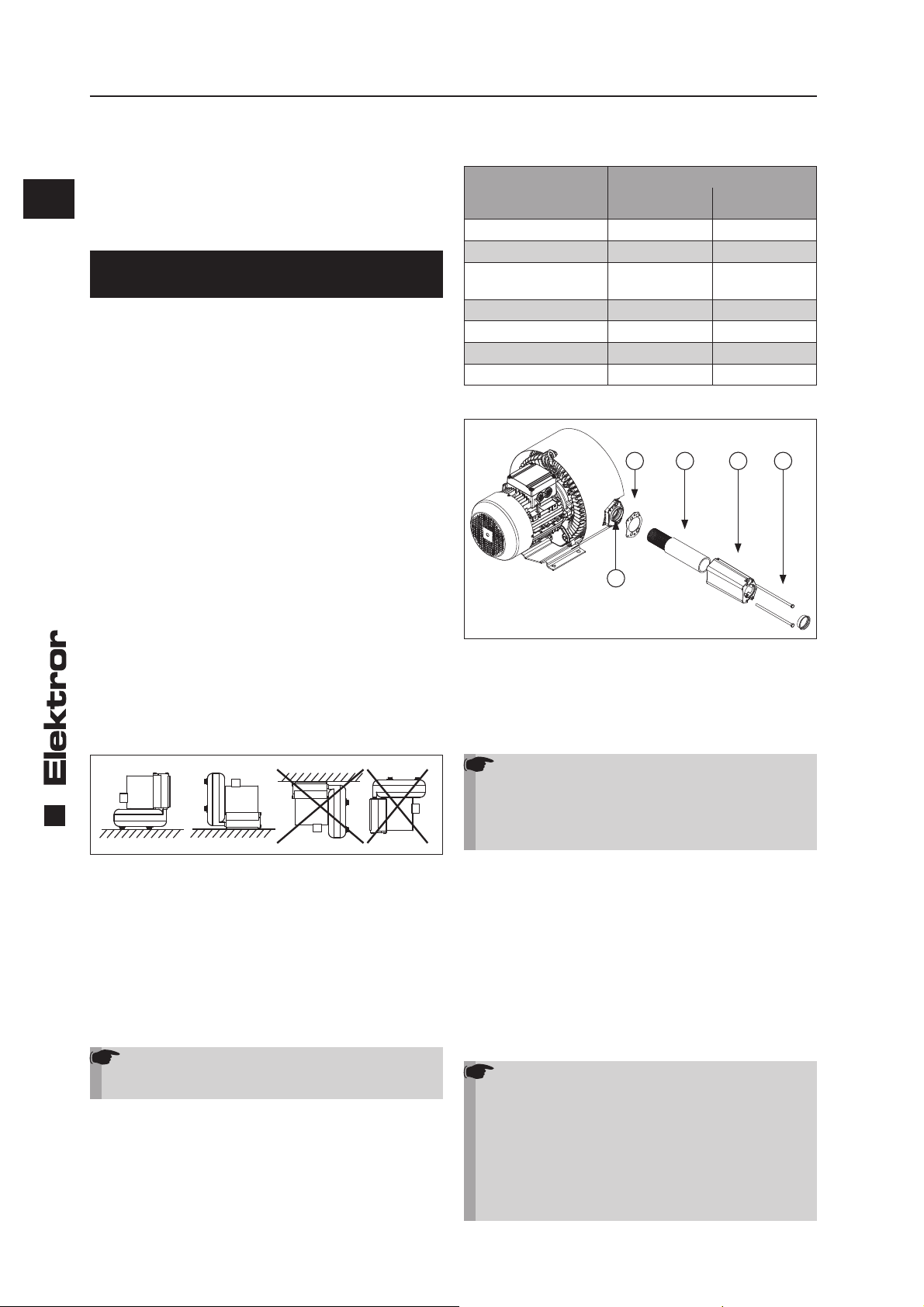
3.3 Montaža stranskih dušilcev zvoka, serija 2SD *2*
3
5
• Vstavek za dušenje zvoka (1) potisnite v ohišje dušilca zvoka (2).
• Tesnilo (3) poravnajte s pomočjo vijakov (4), nameščenih v
dušilcu zvoka, in komponente pritrdite na ohišju ventilatorja
(5).
3.4 Električni priključek
Napotek!
Dela, opisana v tem poglavju, sme izvajati samo
elektrotehnik. Priključek je treba izvesti v skladu z
vezalno shemo v omarici s sponkami in veljavnimi
predpisi na mestu izvedbe.
1
2
4
• Noge oz. konzole kompresorja s stranskim kanalom so
konstruirane samo za lastno težo kompresorja.
• Odprto sesalno ali pihalno odprtino prekrijte z zaščitno
rešetko v skladu z DIN EN ISO 13857.
4
• Poskrbite za zadostno prezračevanje motorja. Dovoljene
temperature okolja pri:
Elektro motor z nazivno napetostjo 50 Hz ali 60 Hz, posebnimi napetostmi, multi-napetostnimi motorji, FU-združljivimi
različicami, FUK različicami, UL-certifi ciranimi napravami:
• Temperatura okolice -20°C do + 40°C
Opomba!
Motorji Elektror so skladno s standardom IEC
60038 na splošno konstruirani za razširjeno napetostno območje ±10 %.
• Stanje vgradnje na sistem prezračevanja pogonskega
motorja ne sme vplivati.
Minimalna razdalja pokrova ventilatorja
(za sesanje hladnega zraka)
Eno- in dvostopenjsko
puhalo s stranskim
kanalom
1SD 2... / 2SD 2... 34 1,34
1SD 3... / 2SD 3... 34 1,34
1SD 4... / 2SD 4...
1SE 4...
Minimalna razdalja pokrova
ventilatorja s sesanjem
[mm] [palcev]
34 1,34
Kot pogonski motorji se uporabljajo motorji s trifaznim ali izmeničnim tokom. To je na napravi označeno s črko D (trifazni
tok, 3~) ali E (enofazni izmenični tok 1~).
• Pogonski motor je treba zavarovati z zaščitnim stikalom
motorja (ne velja za naprave, ki delujejo s frekvenčnim
pretvornikom). Za naprave, ki delujejo s frekvenčnim
pretvornikom, je treba na pretvornik priključiti obstoječi
nadzornik temperature (odpiralni kontakt) in izvesti anali zo.
• Preverite, ali se omrežna napetost ujema s podatki na
tablici naprave.
• Priključek zaščitnega vodnika je na voljo v omarici s
sponkami.
Napotek!
Pri obratovanju pogonskega motorja s frekvenčnim pretvornikom je treba dodatno upoštevati
naslednje:
• Oskrbovalna napetost frekvenčnega pretvornika
sme brez fi ltra motorja znašati največ 400 V. Pri
daljših napeljavah, višjih oskrbovalnih napetostih
pretvornika in/ali prekoračitvi vršnih napetosti
(maks. 1.300 Vpk) na sponkah motorja, je treba
namestiti primerne priprave, npr. fi lter motorja za
njegovo zaščito. V zvezi s tem se obrnite na dobavitelja pretvornika. Če je fi lter motorja del obsega
dobave, ga je treba namestiti med pretvornikom
in motorjem. Poskrbite za dovolj prostega prostora v stikalni omarici in upoštevajte predpise
za namestitev in montažo v navodilih za uporabo proizvajalca frekvenčnega pretvornika/fi ltra
motorja.
• Maksimalna dolžina napeljav med motorjem
in frekvenčnim pretvornikom ne sme preseči 20
m in jo je treba izvesti s primernim oklepljenim
9016329 01.20/09

www.elektror.com Navodila za uporabo in montažo 1SD, 2SD
kablom, po možnosti po neposredni poti in brez
dodanih spončnih/vtičnih povezav.
• Oklepni oplet na priključnem kablu mora biti
neprekinjeno in na obeh straneh, se pravi na
frekvenčnem pretvorniku in na motorju, električno nizko uporovno povezan z ozemljitvenim
sistemom. Na strani motorja je treba v ta namen
uporabiti primerna EMC-kabelska privitja, ki imajo
nizko uporovni stik z oklepom kabla po vsem
obsegu.
Nadaljnje informacije o primerni, elektromagnetno združljivi
namestitvi in montaži poiščite v napotkih v navodilih za uporabo in montažo dobavitelja frekvenčnega pretvornika.
3.4.1 Vezava za trifazno puhalo s stranskim kanalom
Opozorilo!
Nevarnost zaradi razrahljanih in napačno prite-
gnjenih spojev!
Napačno pritegnjeni in razrahljani spoji povzro-
čijo električne udare, požare, stvarno in osebno
škodo!
Preverite rahlost spojev in jih pritegnite v skladu
s priteznimi navori v spodnji preglednici.
W2 U2 V2
U1 V1 W1
W2 U2 V2
U1 V1 W1
L1 L2 L3 L1 L2 L3
(L3) (L1) (L3) (L1)
-vezava Y-vezava
(nizka napetost) (visoka napetost)
Navojni vijak Kažejo navor
M4 1,2 Nm
M5 2,0 Nm
M6 3,0 Nm
M8 6,0 Nm
Preverjanje smeri vrtenja
Puhalo s stranskim kanalom vklopite. Smer teka rotorja se
mora ujemati s smerno puščico na pokrovu ventilatorja.
Smer pretoka zraka se mora ravno tako ujemati s smernimi
puščicami na ohišju dušilca zvoka. V primeru napačne smeri
vrtenja je treba zamenjati L1 in L3.
Zagon zvezda-trikot
Motorji z več kot 3,0 kW moči so predvideni za zagon zvezda-trikot na oskrbovalnem omrežju. Za neposreden vklop
(visok kratkostični tok v trenutku vklopa) se v zvezi s pogoji
posvetujte s svojim podjetjem za električno oskrbo.
3.4.2 Vezava za puhalo s stranskim kanalom na
enofazni izmenični tok
3.4.3 Dodatne sponke
Priključne sheme za nadzornik temperature (odpiralni kontakt) so priložene v omarici s sponkami motorjev.
4 PODATKI O OBRATOVANJU IN
UPORABI
4.1 Osnovni napotki
Upoštevajte napotke o predvideni uporabi, opisane v točki
1.1, ter varnostne napotke, opisane v točkah 1.2 do 1.11.
Če med obratovanjem pride do prekoračitve nazivnega toka
pogonskega motorja, preverite, ali se omrežna napetost in
frekvenca ujemata s podatki naprave.
Po zaščitnih odklopih kot npr. sprožitev zaščitnega stikala
motorja, reakcija nadzornika temperature (odpiralni kontakt)
ali zaščitni odklop prisotnega frekvenčnega pretvornika je
ponovni zagon naprave dovoljen šele po identifi kaciji in od-
pravi vzroka motnje.
Pri puhalih s stranskim kanalom, ki jih ni mogoče uporabljati
v skladu z vsemi karakteristikami, lahko v primeru prevelikega upora naprave pride do preobremenitve motorja (previsoka vhodna moč).
Če preobremenitve zaradi upora naprave ni mogoče izključiti, je treba predvideti omejevalni ventil na tlačni oziroma na
sesalni strani.
Napotek!
Serije 2SD ni dovoljeno uporabljati z omejevalnim
ventilom kot trajno preobremenitveno zaščito.
Puhala s stranskim kanalom ni dovoljeno izpostavljati obremenitvam zaradi nihanja ali udarcev.
4.2 Delovanje frekvenčnega pretvornika
Z uporabo frekvenčnega pretvornika je možno obsežnejše
področje nastavljanja števila vrtljajev, pri tem pa se med
praznim tekom in maks. obremenitvijo puhala s stranskim
kanalom pojavi samo majhna razlika v številu vrtljajev, ki je
odvisna od obremenitve.
Za nemoteno obratovanje puhala s stranskim kanalom je
pomembno, da pretvornik izpolnjuje naslednje zahteve:
• Moč pretvornika je enaka ali večja od moči motorja *)
• Tok pretvornika je enak ali večji od moči motorja *)
• Izhodna napetost pretvornika je enaka nazivni napetosti
motorja
• Napajalna napetost max. 480V, vključno s 5% napetostno
toleranco
• Frekvenca pulzov pretvornika mora znašati 8 kHz, ker
nižja frekvenca pulzov povzroča močan hrup motorja
•
Vrednosti za največje in najmanjše frekvence so pod 1.10.
• Pretvornik mora imeti priključek za nadzornik temperature
(odpiralni kontakt)
*) glede vrednosti glejte tablico s podatki
Motor se lahko uporablja s trikotno ali zvezdno vezavo, odvi-
sno od vhodne napetosti pretvornika.
SL
5
Z2 U2
U1 Z1
L1 N L1 N
Tek v desno Tek v levo
9016329 01.20/09
Z2 U2
U1 Z1

Navodila za uporabo in montažo 1SD, 2SD www.elektror.com
SL
6
Obvezno je treba nastaviti spodnjo dodelitev U/f na
pretvorniku.
B
prepovedano
območje
f
B
f
0
in UB = glejte tablico s podatk
B
V primeru neupoštevanja se tok motorja nesorazmerno poveča in pogonski motor ne doseže nazivnega števila vrtljajev.
Napotek!
V nobenem primeru ni dovoljeno na pretvorniku nastaviti višje frekvence (števila vrtljajev) od
frekvence (fB), ki je navedena na tablici s podatki,
ker sicer pride do preobremenitve motorja ali pa
uničenja puhala s stranskim kanalom zaradi povečanega števila vrtljajev. Na pretvorniku tudi ni
dovoljeno nastaviti tako imenovane „ojačitve (an.
Boost)“, ker bi tako prišlo do prekomerno visokega segrevanja pogonskega motorja. Temperaturna tipala je treba v zaščito pogonskega motorja
priključiti na ustreznih vhodih pretvornika. Motorji
z enofaznim izmeničnim tokom niso primerni za
delovanje s pretvornikom.
Obvezno je treba upoštevati napotke za namestitev in varnost, navedene v priročnikih za uporabo
in namestitev, ki jih priložijo dobavitelji frekvenčnih pretvornikov, da tako zagotovite varno in
nemoteno obratovanje.
Zaščita s pomočjo zaščitnega stikala za okvarne tokove
(zaščitno FI-stikalo):
Frekvenčni pretvorniki IGBT načeloma ustvarjajo uhajave
tokove >=3,5 mA. Ti uhajavi tokovi lahko privedejo do napačnih sprožitev v napravah, ki so zavarovane z zaščitnim
FI-stikalom za diferenčni tok 30 mA.
V primeru napake lahko okvarni tokovi tudi tečejo kot enosmerni tok po zaščitnem vodniku. Če je na oskrbovalni strani
potrebna zaščita s pomočjo zaščitnega FI-stikala, je treba
obvezno uporabiti zaščitno FI-stikalo z občutljivostjo na vse
vrste tokov (tipa B). Uporaba napačnega zaščitnega FI-stikala drugega tipa kot B lahko v primeru napake privede do
smrti ali težkih poškodb.
Za izpolnjevanje standarda EN 61800-5-1 je treba povezavo
z zaščitnim vodnikom izvesti dvojno, preko ločenih sponk ali
s presekom zaščitnega vodnika najmanj 10 mm² Cu.
Obratovanje in priključitev na javna oskrbovalna omrežja:
Večina frekvenčnih pretvornikov je predvidena za uporabo
na industrijskih oskrbovalnih omrežjih.
Če naj se pretvornik
za uporabo priključi neposredno na oskrbovalno omrežje, je
morebiti treba v omrežno napeljavo vgraditi dodatne priprave
za odpravljanje motenj, na primer omrežno dušilko. Nadaljnje informacije najdete v navedbah proizvajalca pretvornika.
5 PODATKI O VZDRŽEVANJU
Obrabni deli so podvrženi priporočenim vzdrževalnim intervalom in zanje veljajo jamstveni zahtevki (glejte 5.1 do 5.4).
Življenjska doba obrabnih delov (krogličnih ležajev in fi ltrov)
je odvisna od obratovalnih ur, obremenitve in drugih vplivov
kot temperatura itd.
Ukrepe za in pri vzdrževanju in servisiranju smejo izvajati
samo osebe z ustreznim strokovnim znanjem in izkušnjami,
ki se za to področje redno usposabljajo. Pri tem je treba poleg ustreznih navodil za uporabo naprave in predpisov ter
priporočil celotne naprave upoštevati naslednje:
Intervali za preglede in vzdrževanje:
Odvisno od obratovalnih ur, obremenitev in pogojev uporabe
mora obratovalec sam določiti intervale čiščenja, pregledovanja in vzdrževanja.
Takojšnji pregled in vzdrževanje:
Pri pojavu vibracij in nihanj, zmanjšani zmogljivosti zraka.
Napotek!
Popravila sme izvajati samo proizvajalec. Pri
popravilih: v primeru sprememb ali zamenjave
sestavnih delov, ki jih izvedejo tretje osebe, ne
prevzamemo nobene odgovornosti in jamstva.
5.1 Kroglični ležaji
Opomba!
Kompresorji s stranskim kanalom so opremljeni
z zaprtimi žlebastimi krogličnimi ležaji, ki jih ni
treba dodatno mazati.
Opomba!
Pri vzdrževanju in pred vsakim ponovnim zagonom preverite kroglične ležaje.
Obratovanje je dovoljeno samo z brezhibnimi
krogličnimi ležaji!
Opomba!
Pri pogostem speljevanju in ustavljanju je potrebna predčasna zamenjava ležajev. Za določitev
časa potrebne menjave ležajev je odgovorno
vzdrževalno in servisno osebje po lastni presoji.
Naprave
Serija 1SD/2SD
Priporočilo za menjavo krogličnih ležajev
- Pred dosegom najkrajše življenjske dobe
- Najkasneje 30 mesecev po predaji
- Po 6 mesecih preverite čas skladiščenja, po potrebi jih
zamenjajte
Najkrajša življenjska doba
krogličnih ležajev
vodoravna
motorna gred
22.000
Ure
navpična
motorna gred
11.000
Ure
5.2 Fini fi lter
Stopnjo umazanosti fi ltrirnih vstavkov je treba preverjati v re-
dnih časovnih razmikih, odvisno od pogojev uporabe/okolice.
Prepustnost fi ltrov mora torej obratovalec zagotavljati. Fini
fi lter je treba namestiti vodoravno, da pri vzdrževalnih delih
v puhalo s stranskim kanalom ne more zaiti umazanija. Pri
navpični vgradnji fi nega fi ltra je treba pred začetkom čišče-
nja/vzdrževanja z naprave demontirati celotni fi lter.
9016329 01.20/09

www.elektror.com Navodila za uporabo in montažo 1SD, 2SD
5.3 Omejevalni ventil
Omejevalni ventil je varnostni ventil, pri katerem je treba v rednih razmikih odvisno od pogojev uporabe preveriti delovanje. Pri preverjanju je treba zapreti obratovalno stran. Omejevalni ventil se mora odzivati pri maksimalni vrednosti tlaka.
Napotek!
Popravila sme izvajati samo proizvajalec. Če
popravila izvede tretja oseba, ne prevzamemo
nobene odgovornosti.
5.4 Čiščenje
Čiščenje ali vzdrževanje ne sme privesti do poškodb ali sprememb naprave in njenih sestavnih delov, neugodno vplivati
na varnost in zaščito zdravja, ravno tako ne sme priti do poslabšanja uravnoteženosti rotorja.
6 INFORMACIJE V ZVEZI Z VARNOSTJO
PRI JEMANJU IZ OBRATOVANJA IN
RAZSTAVITVI
Ločevanje električnih povezav in vse druge elektrotehnične
ukrepe v povezavi z jemanjem naprave iz obratovanja sme
izvajati samo elektrotehnik.
Razstavljanje naprave je dovoljeno šele, ko so se zaustavili
vsi vrteči deli in ponovni zagon ni več mogoč.
SL
Pri razstavljanju in prevažanju morate upoštevati predpise v
poglavju 2.1 Prevoz in ravnanje. Pri odstranjevanju napravo
obravnavajte kot industrijski odpadek.
Deli naprave so iz materialov, ki jih je mogoče reciklirati, na
primer aluminija, nerjavnega jekla, bakra in umetnih mas.
Določeni deli pa zahtevajo posebno obravnavo (npr. frekvenčni pretvornik). Upoštevati je treba nacionalne in krajevne zakonske predpise za odstranjevanje ter recikliranje.
7 JAMSTVO IN IZKLJUČITEV JAMSTVA
Odgovornost za predvideno uporabo naprave nosi obratovalec.
Podj. Elektror odklanja vsakršno odgovornost za nepredvideno uporabo njegovih naprav in komponent.
To še posebej velja za posebne načine in pogoje uporabe, ki
niso izrecno usklajeni s podj. Elektror.
Elektror poleg tega odklanja vsakršno odgovornost za spremembe ali predelave dobavljene naprave in njenega pribora.
Podj. Elektror tudi ne odgovarja za nestrokovno, prepozno
izvedena ali neizvedena vzdrževalna dela in popravila ali za
primere, ko teh ni izvedlo strokovno osebje podj. Elektror, ter
za njihove morebitne posledice.
7
9016329 01.20/09

Navodila za uporabo in montažo 1SD, 2SD www.elektror.com
SL
8 IZJAVA O VGRADNJI V SKLADU S PRILOGO II 1 B
IZJAVA O SKLADNOSTI V SKLADU S 4. ČLENOM 1. ODSTAVKA DIREKTIVE EVPG
Podjetje
Elektror airsystems gmbh
Hellmuth-Hirth-Straße 2
D-73760 Ostfi ldern
kot proizvajalec izjavlja, da izdelek, na katerega se nanaša ta izjava, ustreza spodaj navedenim bistvenim zahtevam Direktive o
strojih (2006/42/ES).
Opis delno dokončanega stroja:
Enostopenjsko puhalo s stranskim kanalom: 1SD 210, 1SE 210, 1SD 310, 1SD 410, 1SE 410, 1SD 510, 1SD 510 FU/FUK,
1SD 710, 1SD 810, 1SD 910
Dvostopenjsko puhalo s stranskim kanalom: 2SD 220, 2SD 320, 2SD 420, 2SD 520, 2SD 720, 2SD 820, 2SD 920
Dvosmerni kompresor stranskih kanalov: 2SD 740, SD 840
Serijska številka in leto izdelave sta navedena na tablici s podatki in pripadajoči dobavnici.
Navedba bistvenih zahtev Direktive o strojih (2006/42/ES), s katerimi je delno dokončan stroj v skladu:
Direktive o strojih (2006/42/ES), Priloga I, členi 1.1.2, 1.1.3, 1.1.5, 1.3.2, 1.3.3, 1.3.4, 1.3.7, 1.5.1, 1.6.1, 1.7.1, 1.7.3
Direktiva o elektromagnetni združljivosti (2014/30/EU)
Direktiva o okoljsko primerni zasnovi izdelkov, povezanih z energijo (2009/125/ES).
Naveden delno dokončan stroj poleg tega izpolnjuje vse določbe Direktive o električni opremi (2006/95/ES) v skladu s Prilogo I,
št. 1.5.1. Direktiva o strojih.
Dajanje delno dokončanega stroja v obratovanje je prepovedano, dokler ni dokončan stroj, v katerega bo vgrajen, razglašen za
skladnega z določbami Direktive o strojih (2006/42/ES).
Uporabljeni so naslednji harmonizirani standardi:
DIN EN ISO 12100 2011 Varnost strojev – Osnovni pojmi, splošna načela načrtovanja,
1. del: Osnovna terminologija, metodologija
DIN EN 60034-1 2011 Električni rotacijski stroji, 1. del: Nazivni podatki in preskus lastnosti
DIN EN 60034-5 2007 Električni rotacijski stroji, 5. del: Stopnja zaščite, ki jo
zagotavlja celovita zasnova rotacijskih električnih strojev (koda IP) – Razvrščanje
DIN EN 60034-30-1 2014 Rotacijski električni stroji – 30. del: opredelitev učinkovitosti trifaznih motorjev s
kletkastim rotorjem, brez motorjev z možnostjo menjave polov (koda IE)
DIN EN 60204-1 2019 Varnost strojev – Električna oprema strojev,
1. del: Splošne zahteve
DIN EN 60664-1 2008 Uskladitev izolacije za opremo v okviru nizkonapetostnih sistemov,
1. del: Načela, zahteve in preskusi
8
Podjetje Elektror airsystems gmbh se kot proizvajalec obvezuje, da bo ustrezno dokumentacijo v zvezi s tem delno dokončanim
strojem na zahtevo predložil pristojnim nacionalnim organom v elektronski obliki ali na papirju.
Ustrezna tehnična dokumentacija za ta delno dokončani stroj v skladu s Prilogo VII del B je bila sestavljena.
Pooblaščena oseba za dokumentacijo je gospod Kevin Kargar, tel. +49 711 31973-1179.
Kreher (poslovodja)
Ostfi ldern, 10.01.2020
9016329 01.20/09
www.elektror.com Navodila za uporabo in montažo 1SD, 2SD
SL
9016329 01.20/09
9
Operating and assembly instructions 1SD, 2SD www.elektror.com
EN
10
CONTENT
1 MACHINE SPECIFICATIONS
2 INFORMATION ON TRANSPORTATION, HANDLING
AND STORAGE OF THE MACHINE
3 INFORMATION ON PUTTING INTO SERVICE
4 INSTRUCTIONS FOR OPERATION AND USE
5 INSTRUCTIONS FOR MAINTENANCE
6 SAFETY RELATED INFORMATION ON TAKING OUT
OF OPERATION AND REMOVAL
7 LIABILITY AND EXCLUSION OF LIABILITY
8 DECLARATION OF INSTALLATION CONFORMITY
PURSUANT TO ANNEX II 1 B
9 TECHNICAL SPECIFICATIONS
10 BROKEN VIEW DRAWING
11 GENERAL SPARE PART LIST
These Operating Instructions must be available to operating
personnel at all times. Read these Operating and Assembly
Instructions carefully before installing and putting the side
channel blower into service.
Subject to change without prior notice. If in any doubt, the
manufacturer should be consulted. This document is protected by copyright. It must not be disclosed to third parties without our express written consent. Any form of duplication or
recording and storage in electronic equipment is forbidden.
1 MACHINE SPECIFICATIONS
Please refer to the cover sheet for our address.
For the area of validity of these Operating and Assembly Instructions, please refer to the Declaration of Installation Conformity contained in Annex II 1 B.
The technical specifi cations on page 18 apply to the stand-
ard version. Your side channel blower’s specifi cations may
diff er from these specifi cations (refer to nameplate). If this is
the case, please refer to the enclosed, additionally applicable
documents or your own applicable Operating and Assembly
Instructions.
Nameplate
The data on the rating plate is applicable to connection,
maintenance and ordering of spare parts. Also refer to the
nameplate for the serial number of the appliance and its year
of manufacture.
D-73760 Ostfildern
Germany
Typ Nr.
Mot. EN 60034-1 IP W-Kl.F
kW cos kW cos
Hz min
V V
A A
1.1 Designated use
Operation of the side channel blower is only permissible
within the limits specifi ed on the nameplate. The information
in the following sections must be noted and observed.
The side channel blowers are exclusively designed for conveying gaseous media without solids. Any solid matter or impurities in the medium to be conveyed must be fi ltered out
before they enter the side channel blower.
Use of the side channel blowers for
• aggressive
-1
-1
min
Hz
• abrasive
• sticky
• toxic
• potentially explosive or
• condensate-forming
media is not permissible.
The permissible conveyed medium temperature for the
standard version is -20°C to +40°C. Solid particles or contaminants must be removed by a fi lter unit before entering
the side channel blower.
The ambient temperature must not exceed +40°C or undershoot a minimum of –20°C.
The side channel blower is not suitable for installation outdoors without special measures. The side channel blower is
fundamentally designed for S1 operation (continuous operation). However, a maximum of 30 switching operations per
hour are permitted.
The standard version of the side channel blower is not suitable for use in explosive atmospheres.
Special versions for applications not mentioned above are
available on request. Remodelling and modifi cation of the
side channel blower are not permitted. In the case of special
equipment, the enclosed supplementary Operating and Assembly Instructions must be observed and adhered to. The
supplementary instructions diff er in certain respects from
these Operating and Assembly Instructions.
Elektror side channel blowers off er a high level of operational
reliability. As the side channel blowers are high-powered machines, the safety instructions must be strictly observed in
order to avoid injuries, damage to objects and to the machine
itself.
1.2 Mechanical hazards
The mechanical hazards in Elektror side channel blowers
have been minimised in accordance with the current state
of the art, as well as the requirements for safety and health
protection. To eliminate any further risk on the part of the operator, we recommend that suitable protective gear be used
and worn during all lifecycle phases of the appliance (please
refer to the instructions below).
1.3 Danger of hand injury
The rotating parts inside the appliance pose a high risk of
injury during operation. Before opening, reaching in or inserting tools into the appliance, always shut it down and wait
until all moving parts come to a standstill. Make sure the appliance is reliably protected against restarting while work is
in progress.
Also make sure that no hazardous situation can occur as a
consequence of restarting after shutdown, e.g. as a result of
a power cut or blockage.
1.4 Weight and stability
Beware of falling hazards during transportation and installation in particular. Refer to 2.1 – Transportation and handling,
as well as 3.2 – Installation and assembly.
1.5 Suction eff ect
The side channel blowers produce a powerful suction eff ect.
Warning!
Objects, items of clothing and also hair can be
sucked into the intake port. Risk of injury!
Do not stand near the intake opening during operation. The side channel blower must not under
any circumstances be operated with the intake
port open, and should, therefore, be covered with
a wire guard in conformity with DIN EN ISO 13857
(danger of injury from impeller!)
9016329 01.20/09

Operating and assembly instructions 1SD, 2SDwww.elektror.com
1.6 Blowing eff ect
Warning!
The blowing eff ect is very powerful on the ex-
haust side. Sucked in objects may be ejected at
very high speed (danger of injury).
The side channel blowers are designed for
delivery of clean air only. To reliably prevent the
sucking-in of foreign objects or contaminants,
which might be discharged, these objects have to
be removed before entering into the side channel
blower by installing a fi lter.
Do not reach into the exhaust.
1.7 Temperature
Warning!
The motor-/ side channel blower housing heats
up during operation. If the temperature rises
above +50°C, the side channel blower must be
protected by the operating company against
direct contact (risk of burning!).
1.8 Motor circuit breaker
Before putting the side channel blower into operation, be sure
to safeguard the drive motor with a motor circuit-breaker (this
does not apply to frequency-converter-operated appliances).
Where appliances are frequency-converter-operated, the existing temperature switch (normally-closed contact) must be
connected to the converter and evaluated.
1.9 Noise emission
Note!
Wear hearing protection during operation at a
daily exposure level of 80 dB(A) and above, and/
or a peak sound pressure level of 135 dB(C) and
above.
Failure to do so may cause hearing damage.
The noise generated by a side channel blower is not constant throughout the performance range. For details of radiated noise level, please refer to the table on page 18.
In some cases, sound insulation may be necessary (it is
recommended that emission levels be measured by the
operator). Sound insulation must be provided by the operator to avoid exceeding the statutory maximum levels at the
workplace and in the immediate vicinity of the side channel
blower.
No sound insulation of any kind whatsoever should cause
the ambient temperature to exceed +40°C at the drive motor
(this is not permissible).
The side channel blowers are designed in such a way that
resonance does not generally occur at a constant operating
speed.
This may be induced in certain circumstances when the
speed is changed if the side channel blower is operated on
a frequency converter. These circumstances are also infl u-
enced by the customer’s individual installation situation or
ventilation connection.
These natural frequencies must be excluded by parametrising the frequency converter accordingly should they be present within the speed range of the side channel blower.
Maximum frequency (see
rating plate)
Minimum frequency
50 Hz 5 Hz
60 Hz 5 Hz
> 60 Hz 20 Hz
1.11 Electrical hazards
Danger!
Danger from electric current!
Live components carry current and cause fatal
injuries!
Deactivate the device before opening it, reaching
into it or inserting tools into it; check that components are not live and secure it against reactivation.
2 INFORMATION ON TRANSPORTATION, HANDLING AND STORAGE OF
THE MACHINE
2.1 Transportation and handling
• Before installation and putting into service, check all parts
for transit damage. A damaged side channel blower is a
potential safety hazard and, therefore, should not be put
into service.
• Do not leave the side channel blower unprotected in the
open (protect against ingress of moisture).
• Attach hoist securely. Only use hoists and load suspension
devices with suffi cient load-carrying capacity. Secure the
route of transportation.
EN
11
1.10 Speeds
Warning!
The maximum speed stamped on the motor
rating plate must never be exceeded in order to
prevent personal injury. The side channel blower
is at risk of mechanical damage if the speed is
exceeded. This can cause serious injury or death!
Each component on the side channel blower has unique natural frequencies. These can be induced by certain side channel blower speeds, which may result in resonance mode.
9016329 01.20/09
Note!
The eye bolt on the motor must not be used to lift
the entire side channel blower. This is unsed if
the motor needs to be (dis-)assembled.
2.2 Storage
• Ensure that the discharge and intake connection is locked
• Store the side channel blower
-> preferably in the original packaging
-> in a closed room
Operating and assembly instructions 1SD, 2SD www.elektror.com
EN
12
-> dry and free of dust and vibration
• Range of storage temperature: from -20°C to +60°C
• After a storage period of 6 months, the bearings should
be checked before they are mounted in the side channel
blower.
• Devices may be stored for a maximum of 2 years.
3 INFORMATION ON COMMISSIONING
THE MACHINE
3.1 Basic information
• Prior to the fi rst start-up and before any other start-up, the
proper operating status of the unit must be inspected.
Units that, for example, are found to be defective upon de
livery or during installation, must be examined by qualifi ed
technicians.
• Installation, assembly and operation must only be
performed by properly trained and qualifi ed specialists.
Operation following incorrect installation, maintenance or
unapproved replacement of components constitutes non designated use and renders the warranty void. The result
ant risk shall be borne solely by the customer or owner.
3.2 Installation and assembly
• Protect the side channel blower from the weather and
install it in a horizontal position - see also 1.1. For outdoor
use, protection from the weather must generally be pro vided that fulfi ls the requirements listed in 1.1 Intended
Use and protects the side channel blower from the infl u-
ences of the weather.
• Do not expose to vibrations or shocks. Permissible
vibrational load on side channel blower: refer to ISO
14694, BV-3.
• Standard side channel blowers with base: Bolt securely
to a level and fi rm surface at the place of use, making
sure that the surface has adequate load-bearing capacity
and avoiding vibration transmission or vibrational load.
• Side channel blowers must be secured against turning.
Minimum distances to side channel blower guard
(for sucking in cooling air)
Single- and doublestage side channel
blower
1SD 2... / 2SD 2... 34 1,34
1SD 3... / 2SD 3... 34 1,34
1SD 4... / 2SD 4...
1SE 4...
1SD 5... / 2SD 5... 53 2,09
1SD 7... / 2SD 7... 53 2,09
1SD 8... / 2SD 8... 53 2,09
1SD 9... / 2SD 9... 53 2,09
3.3 Assembling of laterally silencer 2SD *2*-range
• Insert the silencer cartridge (1) in silencer housing (2).
• Adjust the sealing (3) with the in the silencer inserted
screws (4) and fi x it on the side channel blower housing
(5).
3.4 Electrical connection
Note!
The work described in this section may only be
performed by a qualifi ed electrician. Connect the
appliance to the power supply in the terminal box
as per the wiring diagram and in compliance with
the applicable local regulations.
Minimum distance to fan guard
[mm] [inches]
34 1,34
4213
5
• Side channel blower feet and consoles must be designed
only for the respective side channel blower’s own weight.
• Cover open intakes or outlets with protective grating
according to DIN EN ISO 13857.
• Ensure that the motor has adequate ventilation.
Permitted ambient temperatures with:
Elektror motor and a rated voltage of 50 Hz or 60 Hz,
Special voltages, multi-voltage motors, FU-compatible
versions, FUK versions, UL-certifi ed devices:
• Ambient temperature -20°C to +40°C
Note!
As per IEC 60038 Elektror motors are generally
designed for an extended voltage range of ±10%.
• The performance of the drive motor’s ventilation system
must not be impaired by the installation situation.
Three-phase or a.c. motors can be used as drive motors.
In the appliance designation, the letter D stands for threephase a.c. and the letter E for single-phase a.c.
• The drive motor must be protected using a motor overload
switch (this does not apply to frequency converter oper ated appliances). Where appliances are frequency converter-operated, the existing temperature switch
(normally-closed contact) must be connected to the
converter and evaluated.
• Check that the mains voltage matches the ratings on
the nameplate.
• The safety earth terminal can be found in the terminal box.
Note!
For operation of the drive motor with a frequency
converter, the following points should also be
noted:
• The frequency converter supply voltage must
only be a maximum of 400 V without the motor
fi lter. Appropriate measures, such as a motor
fi lter to protect the motor, must be installed on
the motor terminals with longer cables, higher
frequency converter supply voltages and/or if
9016329 01.20/09

Operating and assembly instructions 1SD, 2SDwww.elektror.com
the pulse voltages are exceeded (max. 1000 Vpk
for drive motors up to 0.75 kW, maximum 1300
Vpk for drive motors larger than 0.75 kW). Please
contact the converter supplier in this case. If a
motor fi lter is included in the delivery, this must
be installed between the converter and the motor.
Please ensure that there is suffi cient space in the
switch cabinet and take into account the installation and assembly requirements in the operating
instructions of the frequency converter/motor
fi lter manufacturer.
• The wire running between the motor and the
frequency converter must not exceed a length of
20 m, confi gured as a suitable, shielded cable and
laid by as direct a route as possible, without any
additional plug/clamp connections.
• The braided screen in the connecting cable
must cover the full length of the cable on both
sides, i.e. be connected to the earthing system at
the frequency converter and to the motor using a
low electrical resistance. For this purpose, suitable EMC cable couplings must be used on the
motor side. They must contact the cable shield
around its full circumference and have a low
resistance.
For further information about EMC compliant installation and
assembly, refer to the Operating and Assembly Instructions
issued by the frequency converter manufacturer.
3.4.1 Confi guration for three-phase current side
channel blowers
Warning!
Danger due to loose or improperly tightened con-
nections!
Improperly tightened and loose connections
cause electric shocks, fi res, property damage and
personal injuries!
Check for loose connections and tighten in
accordance with the tightening torques in the following table.
W2 U2 V2
U1 V1 W1
W2 U2 V2
U1 V1 W1
L1 L2 L3 L1 L2 L3
(L3) (L1) (L3) (L1)
-circuit Y circuit
(low voltage) (high voltage)
Threaded bolt Tightening torque
M4 1,2 Nm
M5 2,0 Nm
M6 3,0 Nm
M8 6,0 Nm
Checking the direction of rotation
Switch on the side channel blower. The running direction of
the impeller should correspond to the direction arrow on the
side channel blower cowling. The direction of the air fl ow
must also match the directional arrows on the silencer housing. If the impeller rotates in the wrong direction, then interchange L1 and L3.
Star-delta start-up
Motors with an output above 3.0 kW are provided at the supply mains for star-delta start-up. For direct on-line starting
(high short circuit current at the instant the motor is energised), please contact your local utility for details of conditions.
3.4.2 Confi guration for single-phase a.c.
side channel blowers
Z2 U2
U1 Z1
Z2 U2
U1 Z1
L1 N L1 N
Clockwise rotation Anti-clockwise rotation
3.4.3 Additional clamps
Terminal diagrams for temperature switch (normally-closed
contact) can be found in the motor terminal box.
3.5 Declaration concerning the EMC Directive
(2014/30/EU)
Our side channel blowers are components that are designed
to be installed in other machines or systems by qualifi ed per-
sonnel, i.e. not intended for consumers. The manufacturer
of the fi nal system/machine must guarantee/confi rm that the
fi nal system/machine complies with the EMC Directive.
Side channel blowers with mains operation:
With mains operation to a sinusoidal AC voltage, the asynchronous motors with a squirrel-cage rotor that are built into
the devices meet the requirements of the EC “Electromagnetic Compatibility” Directive 2014/30/EU, taking into account the standards EN 61000-6-4 (Emitted interference in
industrial environments) and EN 61000-6-3 (Emitted interference in residential environments).
Side channel blowers with frequency converter operation (FU):
Prior to the start-up and during operation of the device on a
frequency converter (provided that this is suitable) it is essential that the EMC instructions from the frequency converter manufacturer and the information in the Elektror operating
and assembly instructions are observed in order to meet the
requirements of the EC “Electromagnetic Compatibility” Directive 2014/30/EU.
If the device is delivered together with a frequency converter
package for switch cabinet or wall mounting closer to the motor, it is possible to comply with EN 61800-3 category C2 (Industrial environments), taking into consideration the abovementioned EMC instructions.
Warning!
This product may cause high-frequency interference in a residential environment that may
require screening measures.
Side channel blowers with an in-built frequency converter (FUK):
Devices with an in-built frequency converter meet the requirements of the EC “Electromagnetic Compatibility” Directive 2014/30/EU under consideration of EN 61800-3 Category C2 (industrial environment), taking into account the EMC
instructions from the frequency converter and the information
in the Elektror operating and assembly instructions.
EN
13
9016329 01.20/09

Operating and assembly instructions 1SD, 2SD www.elektror.com
EN
14
Warning!
This product may cause high-frequency interference in a residential environment that may
require screening measures.
A CE conformity assessment with the relevant standards and
guidelines must be carried out in all cases before the startup.
4 INSTRUCTIONS FOR OPERATION
AND USE
4.1 Basic information
Please observe the notes on designated use in section 1.1,
as well as the safety guidelines in sections 1.2 to 1.11.
If electrical current drops below the rated current of the drive
motor during operation, check to see if the mains voltage and
frequency match the appliance ratings.
After protective shutdowns, e.g. tripping of the motor circuitbreaker, activation of the temperature switch (normally-closed
contact), or after a protective shutdown of the frequency converter during FU applications, the appliance must not be restarted until the problem has been identifi ed and eliminated.
If the side channel blower cannot be operated over the whole
range of the characteristic curve, the motor may overload
if the system resistance is too low (excessive current consumption). If the possibility of overload due to system resistance cannot be excluded, a relief valve must be provided on
the discharge or intake side
Note!
It is not permitted to operate the 2SD range
with a relief valve as permanent overload protection.
The side channel blower must not be subjected to vibration
or impact loads.
4.2 Frequency converter operation
A frequency converter is used, allowing a wide range of
speed adjustments. There is only a small, load-related diff er-
ence in rpm between idle state and the max. load of the side
channel blowers.
To ensure trouble-free operation of the side channel
blowers, it is important that the converter meet the
following requirements:
• Converter output equal to or greater than motor power
output *)
• Converter current equal to or greater than motor current *)
• Converter output voltage equal to rated motor voltage
• Supply voltage max. 480V, including 5% voltage tolerance
• The pulse frequency of the converter should be 8 kHz,
since a lower pulse frequency can cause very noisy motor
operation.
• The values for the maximum/minimum frequency can be
found at 1.10.
• The converter should have a connection for a temperature
switch (normally-closed contact)
*) Refer to the rating plate for data
The motor can be operated in a delta or star-point confi gu-
ration, depending on the input voltage of the converter.
.
The following U/f assignments must be confi gured at the
converter.
B
Prohibited
range
0
f
If this is ignored, the motor current will increase disproportionately and the drive motor will fail to achieve its rated speed.
and UB = refer to rating plate
B
Warning!
To avoid personal damage, destruction of the
side channel blower or motor overload, a higher
frequency (speed) than the frequency (fB) specifi ed on the rating plate must never be set on the
converter otherwise the motor may be overloaded
or the side channel blower destroyed due to
the increased speed. The temperature sensors
are connected to the corresponding converter
inputs to protective the drive motor. Single-phase
alternating current motors are not suitable for
converter operation.
It is absolutely essential that you observe the
installation and safety instructions described in
the respective operating or application manuals
provided by the frequency converter supplier to
guarantee a safe and trouble-free operation.
It is also important to note that special ambient
conditions may lead to a high level of contamination of the cooling fi ns with the FUK devices. The
frequency converter switches off if the cool-
ing output on the cooling fi ns is not adequate.
Regular cleaning is required for devices in these
environments.
Note!
The following times apply for the respective
device motor output class (see rating plate) with
run-up/expiry as well as speed changes in order
to to avoid high component loads and faults in
the converter operation:
Device motor output
f
B
Run-up time
[s]
Expiry time
[s]
Motor output < 0.25 kW 5 10
0.25 kW < Motor output
<=3.0 kW
3.1 kW < Motor output
<= 7.5 kW
7.6 kW < Motor output
<= 11.0 kW
11.1 kW < Motor output
<= 30.0 kW
A uniform run-up and expiry must be guaranteed within the
run-up and expiry times.
No speed changes must occur during operation that exceed
the speed change during run-up and expiry.
10 20
20 40
30 60
30 100
Protection by residual-current-operated circuit breaker
(FI circuit-breaker):
IGBT frequency converters produce discharge currents of
>=3.5 mA due to their design principle. These discharge currents can lead to unwanted tripping in systems protected by
9016329 01.20/09

Operating and assembly instructions 1SD, 2SDwww.elektror.com
a 30 mA-FI circuit-breaker.
If a fault occurs, fault currents can also discharge through the
PE conductor as direct current. If protection is needed on the
supply side by means of an FI circuit-breaker, then an ACDC
sensitive (type B) FI circuit-breaker must be used. Use of an
FI circuit-breaker other than type B can cause death or serious injury if a fault occurs.
To meet the EN 61800-5-1 standard, the PE conductor must
be duplexed and routed through separate terminals or have
a cross-section of at least 10 mm² Cu.
Operation and connection to public grids:
See 3.5
5 INSTRUCTIONS FOR MAINTENANCE
Wear parts are subject to the recommended maintenance intervals and are an element of valid warranty claims (see 5.1
to 5.4). The service life of wearing parts (ball bearings and
fi lters) depends on the operating hours, the load and other
infl uences, such as temperature, etc.
Maintenance and servicing may only be performed by persons with the necessary expertise and regular training. In addition to the appliance’s operating instructions and the regulations and recommendations for the system as a whole, the
following points should be observed:
Inspection and maintenance intervals:
The operator must set the cleaning, inspection and maintenance intervals himself according to operating hours, load
and operating conditions.
Immediate inspection and maintenance
The side channel blower must be inspected immediately if
vibrations or reduced air fl ow are observed.
Note!
Repairs must be carried out by the manufacturer.
We cannot accept any liability for modifi cations
or the replacement of components carried out by
third parties.
5.1 Ball bearings
Note!
The side channel blowers from Elektror are equipped with sealed deep groove ball bearings, which
do not require relubrication.
Note!
Check the ball bearings during servicing and
prior to recommissioning.
Operation is only permitted with fl awless ball
bearings!
Note!
In the event of frequently starting up and shutting
down, premature replacement of the bearings
will be required. Determining the time for replacing the bearings is the sole responsibility of the
maintenance and servicing personnel, who must
make a safety judgement.
Devices
1SD/2SD range
9016329 01.20/09
Minimum ball bearing service
life
Horizontal
motor shaft
22.000
Hours
Vertical motor
11.000
shaft
Hours
Ball bearing change recommendation
- Prior to reaching the minimum service life
- 30 months following delivery at the latest
- Check after 6 months’ storage time; change if necessary
5.2 Micro-fi lters
The degree of clogging of the fi lter elements should be
checked at regular intervals, depending on the ambient
conditions / conditions of use. This means that the user is
responsible for ensuring that the fi lters are permeable. The
micro-fi lter must be positioned horizontally to prevent con-
tamination entering the side channel blower during maintenance work. With vertical micro-fi lter installation, the com-
plete fi lter must be removed from the unit before starting
cleaning/maintenance.
5.3 Relief valve
The relief valve is a safety valve and its operation must therefore be checked at regular intervals depending on application
conditions. The operating side must be closed during inspection. The relief valve must respond at the maximum pressure
value.
Note!
Repairs must be carried out by the manufacturer.
We cannot accept any liability for modifi cations
or the replacement of components carried out by
third parties.
5.4 Cleaning
There is a high risk of injury on the inside of the device due to
rotating parts during operation. Decommission the device in
all cases and wait until all moving parts have stopped before
opening, reaching in or inserting tools into the device.
Secure the device reliably against it being accidentally restarted during the entire period.
Also make sure that no other dangerous situation can arise
when restarting after a standstill, e.g. as a result of a power
failure or blockages.
Cleaning or maintenance must not lead to damage or modifi cations to the device and its components that would infl u-
ence safety or health protection and, for example, impair the
balanced state of the impeller.
When starting up the side channel blower, make sure that
all tools or other foreign objects have been removed from
inside the device and that all covers and protective grilles
have been attached correctly.
6 SAFETY RELATED INFORMATION
ON TAKING OUT OF OPERATION AND
REMOVAL
The disconnection of all electrical connections and any other
electrical work in connection with decommissioning must
only be carried out by a qualifi ed electrician.
The device should be dismantled only when all rotating parts
have come to a standstill and cannot be restarted.
The guidelines set out in 2.1 Transport and Handling must be
observed when dismantling and removing it.
Treat the device as industrial waste when disposing of it.
The device parts are made of recyclable material, such as
aluminium, (stainless) steel, copper and plastic.
EN
15

Operating and assembly instructions 1SD, 2SD www.elektror.com
However, there are components that need special treatment
(e.g. frequency converters). The statutory national and local
disposal and recycling regulations must be observed.
EN
7 LIABILITY AND EXCLUSION OF
LIABILITY
The owner shall bear the responsibility for the correct use of
the device.
Elektror shall not accept any liability for any use of its products and components which is contrary to their intended use.
This shall also apply in particular to use in special applications and under operating conditions that have not been specifi cally agreed with Elektror.
Elektror shall not accept any liability for any modifi cations or
alterations to the device or accessories supplied.
Likewise, Elektror shall not be liable for improper, delayed,
neglected maintenance. Neither shall it be liable for any
cleaning and repair work not carried out by qualifi ed Elektror
specialists, nor for the possible consequences.
16
9016329 01.20/09

Operating and assembly instructions 1SD, 2SDwww.elektror.com
8 DECLARATION OF INCORPORATION ACCORDING TO APPENDIX II 1 B
DECLARATION OF CONFORMITY IN ACC. WITH EVPG (ENERGY CONSUMPTION
RELEVANT PRODUCTS ACT).SECTION 4 PARAGRAPH 1
The manufacturer,
Elektror airsystems gmbh
Hellmuth-Hirth-Str. 2
D-73760 Ostfi ldern
hereby declares that the product to which this declaration refers meets the basic requirements of the Machinery Directive
(2006/42/EC) as set forth below.
Description of incomplete machine:
Single stage side channel blower: 1SD 210, 1SE 210, 1SD 310, 1SD 410, 1SE 410, 1SD 510, 1SD 510 FU/FUK,
1SD 710, 1SD 810, 1SD 910
Double stage side channel blower: 2SD 220, 2SD 320, 2SD 420, 2SD 520, 2SD 720, 2SD 820, 2SD 920
Double fl ow side channel blower: 2SD 740, 2SD 840
Serial number and year of manufacture can be found on the nameplate and on the accompanying delivery slip.
Description of the essential requirements of Machinery Directive (2006/42/EC), with which the partially completed machine
complies:
Machinery Directive (2006/42/EC): Annex I, Articles 1.1.2, 1.1.3, 1.1.5, 1.3.2, 1.3.3, 1.3.4, 1.3.7, 1.5.1, 1.6.1, 1.7.1, 1.7.3
Electromagnetic Compatibility Directive (2014/30/EU)
Eco-design Directive for Energy-related Products (2009/125/EC)
EN
The partially completed machine described here continues to fulfi l the protective regulations of the Low Voltage Directive
(2014/35/EC) according to Annex I, No. 1.5.1 of the Machinery Directive.
The commissioning of the partially completed machine is not permitted until it has been verifi ed that the machine in which the
partially completed machine is to be installed, complies with the provisions of the Machinery Directive (2006/42/EC).
The following harmonised standards were applied:
DIN EN ISO 12100 2011 Safety of machinery, general principles for design,
risk assessment and risk minimisation
DIN EN 60034-1 2011 Rotating electrical machines, Part 1: Rating and performance
DIN EN 60034-5 2007 Rotating electrical machines, Part 5: Degrees of protection provided
by the integral design of rotating electrical machines (IP code) – Classifi cation
DIN EN 60034-30-1 2014
cage-induction motors (IE code)
DIN EN 60204-1 2019 Safety of machinery – Electrical equipment of machines,
Part 1: General requirements
DIN EN 60664-1 2008 Insulation coordination for equipment within low-voltage systems,
Part 1: Principles, requirements and tests
The manufacturer, Elektror airsystems gmbh, undertakes to make the special documentation on this incomplete machine available,
electronically or in hardcopy, to national authorities on demand.
The special technical documentation belonging to this incomplete machine was prepared in accordance with Annex VII Part B.
Mr Kevin Kargar, tel. +49 711 31973-1179, is responsible for the documentation.
Kreher (Managing Director)
Ostfi ldern, 10.01.2020
Rotating electrical machines - Part 30: Effi ciency classes of single-speed, three-phase,
17
9016329 01.20/09

Betriebs- und Montageanleitung 1SD/2SD www.elektror.de
DE
18
9 TEHNIČNI PODATKI / TECHNICAL SPECIFICATIONS
Enostopenjsko puhalo s stranskim kanalom | Single stage side channel blowers
Model
Type
1SD 210
1SE 210
1SD 310
1SD 310
1SD 410
1SD 410
1SD 410
1SD 410
1SE 410
1SD 510
1SD 510
1SD 510
1SD 510
FU/FUK
1SD 510
1SD 510
1SD 510
1SD 710
1SD 710
1SD 710
1SD 710
1SD 710
Mejne vrednosti
Razred
učinkovi-
tosti
Effi ciency
class
-
-
dušilne krivulje
Nadtlak
Frekvenca
V. max.
performance when
used as blower
Frequency
V. max.
[Hz] [m³/min] [mbar] [m³/min] [mbar] [kW] [V] [A] [db (A)] [kg]
Maximum
max. V. max.
pt
max. V. max.
pt
50 1,33 130 1,33 120 0,37 207-253 / 360-440 1,8 / 1,04 53 10
60 1,63 160 1,63 150 0,63 220-250 / 415-480 2,4 / 1,4 56 10
- - 50 1,33 130 1,33 120 0,37 230 2,7 53 10
- - 60 1,63 160 1,63 150 0,43 230 3,2 56 10
-
-
-
-
-
-
-
-
50 1,92 150 1,92 150 0,75 207-253 / 360-440 2,95 / 1,7 55 13
60 2,33 140 2,33 150 1,30 220-250 / 415-480 4,8 / 2,8 57 13
50 1,92 170 1,92 150 1,10 207-253 / 360-440 4,35 / 2,5 55 13
60 2,33 180 2,33 150 1,50 220-250 / 415-480 5,0 / 2,9 57 13
50 2,42 160 2,42 160 0,75 207-253 / 360-440 2,95 / 1,7 63 16
60 2,92 160 2,92 160 1,30 220-250 / 415-480 4,8 / 2,8 64 16
50 2,42 200 2,42 170 1,10 207-253 / 360-440 4,35 / 2,5 63 16
60 2,92 220 2,92 210 1,50 220-250 / 415-480 5,0 / 2,9 64 16
IE3 - 50 2,42 150 2,42 160 0,75 230/400 2,94/1,71 63 19
IE3 - 60 2,92 140 2,92 140 0,86 480 1,67 64 19
IE3 - 50 2,42 210 2,42 180 1,10 230/400 4,0/2,31 63 21
IE3 - 60 2,92 220 2,92 210 1,30 480 2,34 64 21
- - 50 2,42 190 2,42 150 1,10 230 7,3 63 16
- - 60 2,92 190 2,92 180 1,30 230 8,3 64 16
-
-
-
-
-
-
50 3,50 170 3,50 170 1,10 207-253 / 360-440 4,35 / 2,5 64 22
60 4,25 140 4,25 150 1,50 220-250 / 415-480 5,0 / 2,9 70 22
50 3,50 190 3,50 200 1,60 207-253 / 360-440 7,5 / 4,3 64 23
60 4,25 210 4,25 220 2,20 220-250 / 415-480 8,0 / 4,6 70 23
50 3,50 270 3,50 220 2,20 207-253 / 360-440 8,1 / 4,6 60 25
60 4,25 290 4,25 260 3,80 220-250 / 415-480 13,0 / 0,75 70 25
- - 80 5,4 300 5,2 300 3,80 400 7,5 73 28
-
IE3 -
IE3 -
IE3 -
IE3 -
IE3 -
IE3 -
-
-
-
-
-
-
50 3,50 150 3,50 150 1,10 230/400 4,0/2,31 64 29
60 4,25 130 4,25 140 1,30 480 2,34 70 29
50 3,50 220 3,50 230 1,50 230/400 5,2/3,0 64 32
60 4,25 200 4,25 210 1,75 480 2,90 70 32
50 3,50 310 3,50 250 2,20 230/400 7,53/4,35 64 40
60 4,25 320 4,25 280 2,55 480 4,17 70 40
50 5,30 200 5,30 210 2,20 207-253 / 360-440 8,1 / 4,6 69 30
60 6,27 200 6,27 210 3,80 220-250 / 415-480 13,0 / 7,5 72 30
50 5,30 290 5,30 270 3,00 207-253 / 360-440 15,2 / 7,2 69 36
60 6,27 230 6,27 250 4,60 220-250 / 415-480 14,7 / 8,5 72 36
50 5,30 330 5,30 290 4,00 360 - 440 9,0 69 42
60 6,27 330 6,27 330 6,00 415 - 480 10,9 72 42
IE3 - 50 5,30 190 5,30 200 2,20 230/400 7,53/4,35 69 49
IE3 - 60 6,27 180 6,27 190 2,55 480 4,17 72 49
IE3 - 50 5,30 280 5,30 280 3,00 230/400 9,90/5,70 69 54
IE3 - 60 6,27 270 6,27 280 3,46 480 5,40 72 54
Mejne vrednosti
dušilne krivulje
Podtlak
pt
max.
Maximum
performance when
used as extractor
pt
max.
A variable speed drive must be installed with this blower.
Nazivne vrednosti motorja
Moč
motorja
Rated
output
Napetost Vhodna moč
Motor ratings
Voltage
Current
consumption
Maks.
raven
zvočnega
tlaka L
Sound
pressure
level L
A
A
Teža
(pribl.)
Weight
(approx.)
9016329 01.20/09

www.elektror.de Betriebs- und Montageanleitung 1SD/2SD
9 TEHNIČNI PODATKI / TECHNICAL SPECIFICATIONS
Model
Type
1SD 710
1SD 810
1SD 810
1SD 810
1SD 810
1SD 810
1SD 810
1SD 910
1SD 910
1SD 910
1SD 910
1SD 910
1SD 910
Mejne vrednosti
Razred
učinkovi-
tosti
Effi ciency
class
dušilne krivulje
Nadtlak
Frekvenca
V. max.
performance when
used as blower
Frequency
V. max.
[Hz] [m³/min] [mbar] [m³/min] [mbar] [kW] [V] [A] [db (A)] [kg]
Maximum
max. V. max.
pt
max. V. max.
pt
IE3 - 50 5,30 350 5,30 290 4,00 400/690 7,45/4,30 69 63
IE3 - 60 6,27 360 6,27 330 4,60 480 7,40 72 63
-
-
-
-
-
-
50 8,83 200 8,83 200 4,00 360 - 440 9,0 70 54
60 10,33 160 10,33 160 6,00 415 - 480 10,9 74 54
50 8,83 300 8,83 300 5,50 360 - 440 13,3 70 63
60 10,33 280 10,33 300 8,60 415 - 480 15,3 74 63
50 8,83 430 8,83 320 7,50 360 - 440 16,7 70 66
60 10,33 400 10,33 350 9,80 415 - 480 18,2 74 66
IE3 - 50 8,83 180 8,83 200 4,00 400/690 7,45/4,30 70 62
IE3 - 60 10,33 150 10,33 160 4,60 480 7,40 74 62
IE3 - 50 8,83 300 8,83 300 5,50 400/690 10,1/5,83 70 73
IE3 - 60 10,33 250 10,33 270 6,30 480 9,60 74 73
IE3 - 50 8,83 420 8,83 340 7,50 400/690 13,5/7,8 70 77
IE3 - 60 10,33 400 10,33 350 8,60 480 12,90 74 77
-
-
-
-
-
-
50 17,5 190 17,5 210 8,50 360 - 440 18,2 74 93
60 20,8 140 20,8 180 9,80 415 - 480 18,2 84 93
50 17,5 280 17,5 280 12,5 360 - 440 28,0 75 116
60 20,8 260 20,8 270 14,5 415 - 480 26,0 84 116
50 17,5 460 17,5 360 18,5 360 - 440 37,0 75 126
60 20,8 420 20,8 380 21,3 415 - 480 26,5 84 126
IE3 - 50 17,50 190 17,50 200 7,50 400/690 13,5/7,8 74 118
IE3 - 60 20,80 160 20,80 170 8,60 480 12,90 84 118
IE3 - 50 17,50 280 17,50 290 11,00 400/690 19,6/11,3 75 140
IE3 - 60 20,80 260 20,80 270 12,60 480 18,70 84 140
IE3 - 50 17,50 500 17,50 350 18,50 400/690 32,5/18,8 75 162
IE3 - 60 20,80 460 20,80 380 21,30 480 32,40 84 162
Mejne vrednosti
dušilne krivulje
Podtlak
pt
max.
Maximum
performance when
used as extractor
pt
max.
Nazivne vrednosti motorja
Moč
motorja
Rated
output
Napetost Vhodna moč
Motor ratings
Voltage
Current
consumption
Maks.
raven
zvočnega
tlaka L
Sound
pressure
level L
A
A
Teža
(pribl.)
Weight
(approx.)
DE
19
Dvostopenjsko puhalo s stranskim kanalom | Double stage side channel blowers
2SD 220
2SD 320
2SD 420
2SD 420
2SD 420
2SD 420
2SD 520
9016329 01.20/09
-
-
-
-
-
-
-
IE3 - 50 2,50 310 2,50 320 1,50 230/400 5,2/3,0 66 32
IE3 - 60 3,00 280 3,00 300 1,75 480 2,90 69 32
IE3 - 50 2,50 420 2,50 320 2,20 230/400 7,53/4,35 66 35
IE3 - 60 3,00 470 3,00 400 2,55 480 4,17 69 35
-
-
50 1,47 240 1,47 210 0,55 207-253 / 360-440 2,70 / 1,57 55 14
60 1,72 250 1,72 250 0,94 220-250 / 415-480 4,0 / 2,3 61 14
50 2,00 290 2,00 280 1,10 207-253 / 360-440 4,35 / 2,5 58 18
60 2,42 400 2,42 300 1,50 220-250 / 415-480 5,0 / 2,9 60 18
50 2,50 280 2,50 280 1,60 207-253 / 360-440 7,5 / 4,3 66 25
60 3,00 310 3,00 320 2,20 220-250 / 415-480 8,0 / 4,6 69 25
50 2,50 440 2,50 330 2,20 207-253 / 360-440 9,7 / 5,6 66 27
60 3,00 420 3,00 350 3,80 220-250 / 415-480 13,0 / 7,5 69 27
50 3,83 410 3,83 340 3,00 207-253 / 360-440 12,5 / 7,2 72 39
60 4,58 360 4,58 380 4,60 220-250 / 415-480 14,7 / 8,5 74 39

Betriebs- und Montageanleitung 1SD/2SD www.elektror.de
DE
20
9 TEHNIČNI PODATKI / TECHNICAL SPECIFICATIONS
Model
Type
2SD 520
2SD 520
2SD 720
2SD 720
2SD 720
2SD 720
2SD 720
2SD 720
2SD 720
2SD 820
2SD 820
2SD 820
2SD 820
2SD 820
2SD 820
2SD 920
2SD 920
2SD 920
2SD 920
2SD 920
2SD 920
2SD 920
Mejne vrednosti
Razred
učinkovi-
tosti
Effi ciency
class
-
-
dušilne krivulje
Nadtlak
Frekvenca
V. max.
performance when
used as blower
Frequency
V. max.
[Hz] [m³/min] [mbar] [m³/min] [mbar] [kW] [V] [A] [db (A)] [kg]
Maximum
max. V. max.
pt
max. V. max.
pt
50 3,83 440 3,83 390 4,00 360 - 440 10,0 72 44
60 4,58 480 4,58 410 6,00 415 - 480 10,9 74 44
IE3 - 50 3,83 450 3,83 380 3,00 230/400 9,9/5,7 72 53
IE3 - 60 4,58 410 4,58 410 3,46 480 5,40 74 53
-
-
-
-
-
-
-
-
50 5,33 260 5,33 280 3,00 230 / 400 12,5 / 7,2 73 48
60 6,42 200 6,42 230 4,60 277 / 480 14,7 / 8,5 76 48
50 5,33 380 5,33 360 4,00 360 - 440 9,0 73 54
60 6,42 320 6,42 350 6,00 415 - 480 10,9 76 54
50 5,33 500 5,33 440 5,50 360 - 440 13,3 73 66
60 6,42 500 6,42 440 8,60 415 - 480 15,3 76 66
50 5,33 610 5,33 440 7,50 360 - 440 16,7 73 77
60 6,42 660 6,42 460 9,80 415 - 480 18,2 76 77
IE3 - 50 5,33 370 5,33 400 4,00 400/690 7,45/4,30 73 67
IE3 - 60 6,42 320 6,42 350 4,60 480 7,40 76 67
IE3 - 50 5,33 530 5,33 420 5,50 400/690 11,8/6,8 73 82
IE3 - 60 6,42 490 6,42 440 6,30 480 9,60 76 82
IE3 - 50 5,33 610 5,33 420 7,50 400/690 13,5/7,8 73 88
IE3 - 60 6,42 670 6,42 440 8,60 480 12,90 76 88
-
-
-
-
-
-
50 8,67 400 8,67 400 8,5 360 - 440 18,2 74 86
60 10,33 330 10,33 360 9,8 415 - 480 18,2 78 86
50 8,67 600 8,67 430 11,0 360 - 440 19,9 74 104
60 10,33 600 10,33 460 17,3 415 - 480 33,5 78 104
50 8,67 670 8,67 460 15,0 360 - 440 30,5 74 120
60 10,33 750 10,33 490 21,3 415 - 480 36,5 78 120
IE3 - 50 8,67 360 8,67 380 7,50 400/690 13,3/7,68 74 103
IE3 - 60 10,33 320 10,33 330 8,60 480 13,30 78 103
IE3 - 50 8,67 570 8,67 460 11,00 400/690 19,6/11,3 74 135
IE3 - 60 10,33 540 10,33 460 12,60 480 18,70 78 135
IE3 - 50 8,67 800 8,67 480 15,00 400/690 26,5/15,3 74 146
IE3 - 60 10,33 720 10,33 460 17,30 480 26,00 78 146
-
-
-
-
-
-
-
-
50 18,50 270 18,50 300 12,5 360 - 440 28,0 74 187
60 21,83 200 21,83 220 14,5 415 - 480 26,0 78 187
50 18,50 370 18,50 410 16,5 360 - 440 35,0 74 197
60 21,83 300 21,83 340 17,3 415 - 480 33,5 78 197
50 18,50 500 18,50 440 20,0 360 - 440 40,0 74 204
60 21,83 430 21,83 440 23,0 415 - 480 39,5 78 204
50 18,50 590 18,50 440 25,0 360 - 440 52,0 74 211
60 21,83 540 21,83 440 29,0 415 - 480 48,0 78 211
IE3 - 50 18,50 250 18,50 270 11,00 400/690 19,6/11,3 74 195
IE3 - 60 21,83 190 21,83 220 12,60 480 18,70 78 195
IE3 - 50 18,50 370 18,50 410 15,00 400/690 26,5/15,3 74 208
IE3 - 60 21,83 320 21,83 390 17,30 480 26,00 78 208
IE3 - 50 18,50 490 18,50 440 18,50 400/690 32,5/18,8 74 210
IE3 - 60 21,83 430 21,83 460 21,20 480 32,40 78 210
Mejne vrednosti
dušilne krivulje
Podtlak
pt
max.
Maximum
performance when
used as extractor
pt
max.
Nazivne vrednosti motorja
Moč
motorja
Rated
output
Napetost Vhodna moč
Motor ratings
Voltage
Current
consumption
Maks.
raven
zvočnega
tlaka L
Sound
pressure
level L
A
A
Teža
(pribl.)
Weight
(approx.)
9016329 01.20/09

www.elektror.de Betriebs- und Montageanleitung 1SD/2SD
9 TEHNIČNI PODATKI / TECHNICAL SPECIFICATIONS
Dvostopenjski pihalnik s stranskim kanalom | Double fl ow side channel blowers
Model
Type
2SD 740
2SD 740
2SD 840
2SD 840
2SD 840
2SD 840
Mejne vrednosti
Razred
učinkovi-
tosti
Effi ciency
class
-
-
-
-
-
-
-
-
dušilne krivulje
Nadtlak
Frekvenca
V. max.
performance when
used as blower
Frequency
V. max.
[Hz] [m³/min] [mbar] [m³/min] [mbar] [kW] [V] [A] [db (A)] [kg]
Maximum
max. V. max.
pt
max. V. max.
pt
50 8,83 140 8,83 150 4,0 360 - 440 7,8 74 54
60 10,0 90 10,0 100 6,0 415 - 480 9,0 78 54
50 8,83 260 8,83 200 5,5 360 - 440 10,5 74 69
60 10,0 200 10,0 210 8,6 415 - 480 10,3 78 69
50 15,0 180 15,0 200 8,5 360 - 440 18,2 74 91
60 17,5 120 17,5 150 9,8 415 - 480 18,2 78 91
50 15,0 370 15,0 280 11,0 360 - 440 19,9 74 110
60 17,5 350 17,5 310 17,3 415 - 480 33,5 78 110
IE3 - 50 15,00 180 15,00 160 7,50 400/690 13,3/7,68 74 105
IE3 - 60 17,50 120 17,50 120 8,60 480 13,30 78 105
IE3 - 50 15,00 290 15,00 260 11,00 400/690 19,6/11,3 74 137
IE3 - 60 17,50 240 17,50 220 12,60 480 18,70 78 137
Mejne vrednosti
dušilne krivulje
Podtlak
pt
max.
Maximum
performance when
used as extractor
pt
max.
Nazivne vrednosti motorja
Moč
motorja
Rated
output
Napetost Vhodna moč
Motor ratings
Voltage
Current
consumption
Maks.
raven
zvočnega
tlaka L
Sound
pressure
level L
A
A
Teža
(pribl.)
Weight
(approx.)
DE
9016329 01.20/09
21

SL
Navodila za uporabo in montažo 1SD, 2SD www.elektror.com
21
22
10 RISBA V RAZSTAVLJENEM STANJU / BROKEN VIEW DRAWING
3
12 4 5 6
9016329 01.20/09

www.elektror.com Navodila za uporabo in montažo 1SD, 2SD
SL
9016329 01.20/09
11 SPLOŠEN SEZNAM NADOMESTNIH DELOV / GENERAL SPARE PART LIST
SL EN
Pos. Naziv Designation
1 Pena Foam
2 Zaščitna rešetka Protective grating
3 Plošča s sponkami Terminal board
4 Zaščita ležajev Endplate
5 Krilo ventilatorja Blower vane
23
6 Pokrov ventilatorja Blower cowling

Hellmuth-Hirth-Straße 2, D-73760 Ostfi ldern
Postfach 1252, D-73748 Ostfi ldern
+49 711 31973-0
+49 711 31973-5000
support@elektror.de
www.elektror.de
Nadaljnje informacije o naših izdelkih najdete tudi na spletu pod www.elektror.com
Naša upravljanje izdelek vam je na voljo na številki +49 711 31973-1111.
You will fi nd further information about our products on the internet at www.elektror.com
Our Product management will be pleased to answer your queries at +49 711 31973-1111.
9016329 01.20/09
Za tiskarske in vsebinske napake ne prevzamemo odgovornosti. | Errors and omissions excepted.
Pridržujemo si pravico do tehničnih in konstrukcijskih sprememb! | Subject to technical and design modifi cations.
 Loading...