

Page 1

PoroTest® 7
Technical Reference and Operating Manual
Advancing with T echnology ElektroPhysik
Page 2

© B13-A6 08/2014
Subject to change without notice.
ElektroPhysik Dr. Steingroever GmbH & Co. KG
Pasteurstr. 15
D-50735 Cologne, Germany
Tel. +49 (0) 221-75204-0; Fax +49 (0) 221 75204-67
www.elektrophysik.com; info@elektrophysik.com
ElektroPhysik USA
778 West Algonquin Rd., Arlington Heights IL 60005
Phone (847) 437-6616; Fax (847) 437-0053
epusa@elektrophysik.com
Caution!
Safety Note
Please refer to the safety notes in section 2 before starting
operation of PoroT est® 7.
Page 3

Table of contents
Table of Contents
1. General Information...........................E-3
1.1 Applications............................................ E-3
1.2 Description ................................................. E-3
1.3 Supply schedule .................................... E-3
1.4 Accessories............................................. E-4
2. Safety notes.......................................E-4
3. Preparing PoroTest® 7 for
operation ..........................................E-5
4. Preparing the test object....................E-6
5. Selection of the test electrode ...........E-6
6. Instrument settings ..........................E-6
6.1 T est parameters (test volt age) ................. E-7
6.2 Sensitivity.................................................. E-7
6.3 Limit for pores .......................................... E-8
6.4 High voltage trigger ................................. E-8
6.5 Signal LED ................................................ E-8
6.6 Display contrast ......................................... E-9
6.7 Display backlight ....................................... E-9
6.8 Language ................................................... E-9
6.9 Setting mode ............................................ E-9
6.10 Display mode ........................................... E-9
7. General remarks on Operation and
Application .....................................E-10
7. 1 T esting procedure....................................E-1 1
8. Power supply ...................................E-12
9. Charging storage batteries............E-12
10. Changing storage batteries ...........E-12
1 1.Error Messages ...............................E-13
12. Battery charging messages...........E-14
13. T est principle..................................E-15
14. T echnical specification ..................E-16
15.After-sales service ...........................E-18
Index......................................................E-20
ElektroPhysik E-i
Page 4
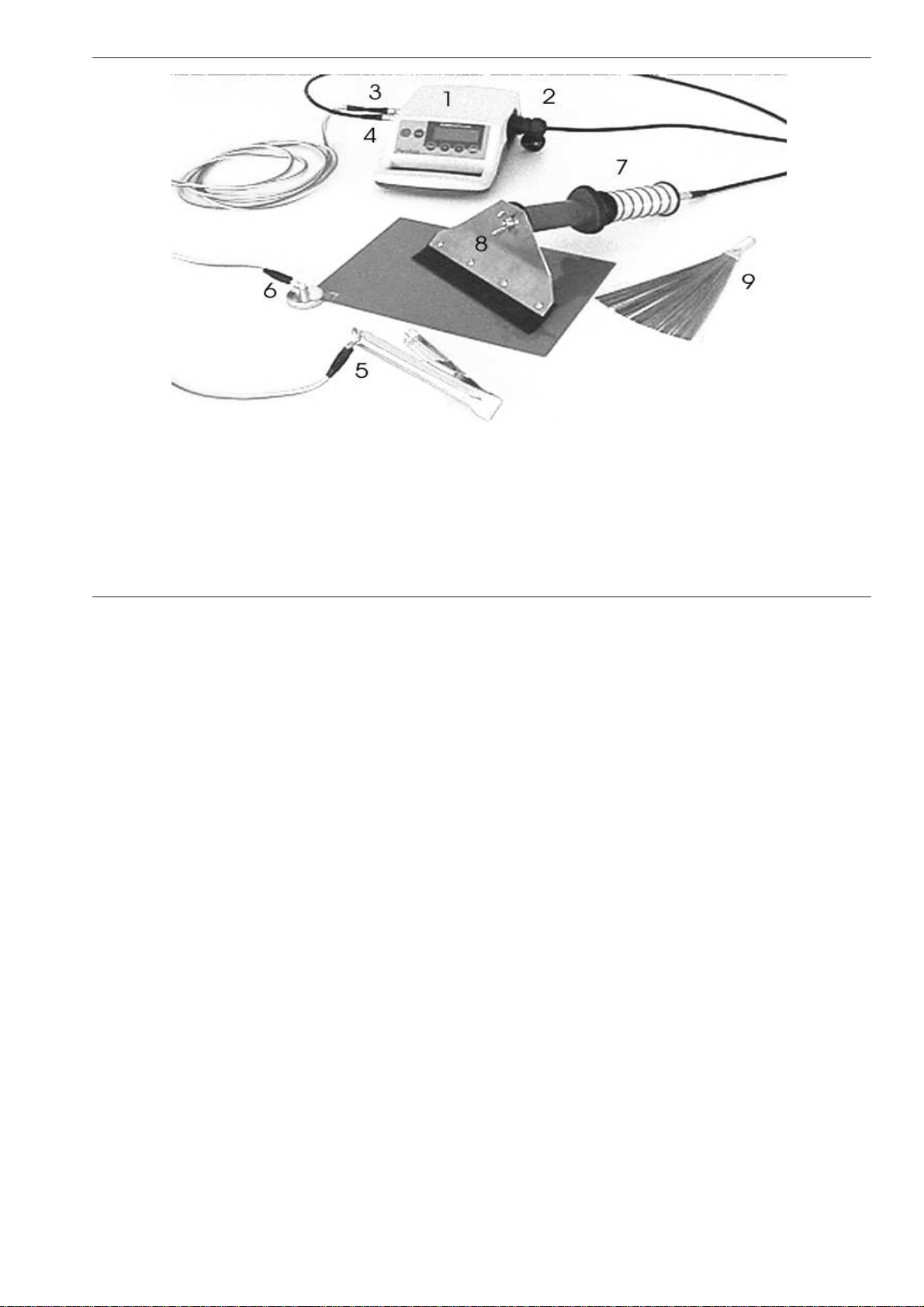
Fig. 1
PoroTest® wiring
5 Cable lug for protection earth with earth clamp
1 PoroTest® control unit
2 Mains cable
3 Equipotential cable (Earting cable) (green/yellow)
4 Connecting cable (probe-control unit) (black)
ElektroPhysik E-1
6 Cable lug for earth magnet or earth clamp
7 High voltage probe
8 Silicon-rubber electrode
9 Metall sweeper electrode
Page 5
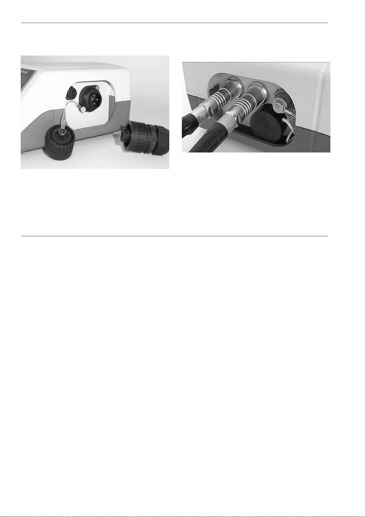
PoroTest® sockets
Mains cable socket
Sockets for earthing cable and high voltage probe
connecting cable
Fig. 3
Fig. 2
E-2 ElektroPhysik
Page 6

General information, Supply schedule
1. General Information
Designed for high voltage porosity detection, PoroT est®
7 conforms to the following industrial standards:
DIN 55670
DIN 50191 (VDE 0104)
DIN EN 61010 /Teil 1 (VDE 0411/ Part 1)
1.1 Applications
PoroTest® 7 holiday detector detects pores and holes
in insulating materials on conductive substrates such
as steel, aluminum, etc. Typical applications: Testing
linings and coatings applied on ducts, pipes, hulls, oil
and storage tanks , enamel, paint, rubber and bitumen
linings, vessels and tanks, GFK and other plastics
materials.Tanks or vessels must be filled with water or
other conductive material. To detect porosity, the
appropriate test voltage specific to the material thickness
is set on the control unit which applies, when activated,
a spark discharge at the moment a material flaw is
detected. In addition to the spark discharge, flaws are
counted and indicated by a visible and audible signal.
Depending on the test electrode, test voltage can be set
from 0.5...7 kV (P7) for coatings from 30 microns to
1.7mm or from 6 to 35kV (P35) for coatings from 1.4mm
to 11,3mm.
1.2 Description
The test instrument consists of a high voltage probe with
an integrated high voltage generator and a test electrode
connected to the probe. The control unit features a digital display and control pad. The control unit housing is
fully portable and made of rugged ABS plastic with an
integrated handle. The high voltage probe and control
unit are connected via a rugged cable
1.3 Supply schedule
- rugged plastics carrying case
- control unit with integrated storage battery
- connecting cable (probe - control unit)
- high voltage probe (optional accessories)
- metal sweeper electrode
- earth magnet
- earth clamp
- equipotential cable, 5 m (16 ft.) length
- mains cable
- shoulder belt
ElektroPhysik E-3
Page 7

Accessories, Safety notes
1.4 Accessories
· Aluminium case
· Brush, rolling spring, ring and right-angle
electrodes in various designs, silicon-rubber
electrode, 200 mm (7.8 ft.) width
· 3-pin plug, cable-free, directly plugs into the
integrated signal contact (make/break
contact).The signal contact is automatically
actuated if a pore is detected and may be used
for an external signal devices.
· Earthing rod
· Earthing/equipotential cable, 10 m (32 ft.) length
· Connecting cable for control unit and high voltage
probe in special lengths: 5m (16 ft.), 10m ( 32 ft.)
· Non-destructive coating thickness gauges, help
you to adjust test voltage specific to coating
thickness
2. Safety notes
- PoroTest® 7 is designed for safe use. When observing the safety notes, operation of the
instrument is absolutely risk free to the operator.
Current and capacitance limits conform to the
German standards DIN EN 61010/ Part 1 (VDE
0411/Part 1).
- Persons with cardiac pacemakers should consult
their physician about the possibility of interference
with the instrument.
- Caution!
Never use unearthed equipment! Before
use, make sure both, PoroT est® 7 and the test
object are well earthed (see section 3.)
- Only use rechargeable NiMH C-cells. Non
rechargeable batteries pose an explosion hazard
if on charge!
- After the control unit has been switched off,
discharge the high-voltage generator to earth.
- Do not carry out high voltage discharge to the
instrument or to the connecting cable between
instrument and probe.
E-4 ElektroPhysik
Page 8
Preparing PoroTest® 7 for operation
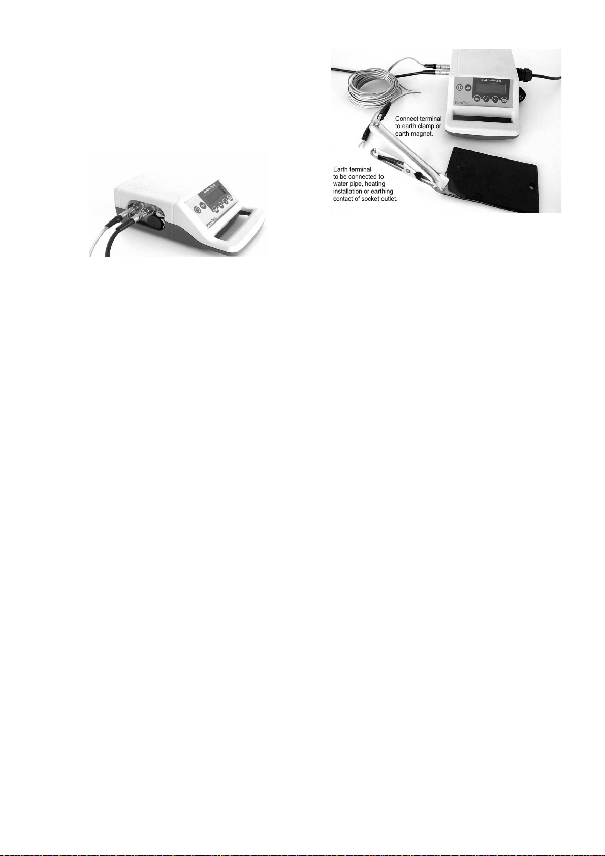
3. Preparing PoroTest® 7 for
operation
1. Plug the yellow/green earth cable into the twopin earth socket of the gauge. Connect one of
the wire ends to the earth clamp or the earth
magnet (for magnetic substrates). Fix the earth
clamp or the earth magnet to an uncoated spot of
the test object (Fig. 5)
Fig. 5
3. Use the wing nut to connect the test electrode to
Fig. 4
Earth cable (yellow / green), left
High voltage cable (black), right
2. Build-up an additional protection earth by securely
connecting the second end of the yellow/green
earth cable to a water pipe, heating installation,
to the earthing contact of a socket-outlet or to
another suitable earthed metal construction. For
in the field testing, the earth rod (available as an
option) should be used.
ElektroPhysik E-5
the high voltage probe (Fig. 1). The met al sweeper
electrode can directly be connected to the high
voltage probe.
4. Use the black high-voltage cable to connect the
high voltage probe to the control unit (4-pin
socket).
5. Hold the high voltage probe by the metal handle
to prevent static charge.
Page 9

Preparing / Instrument settings
6. Switch on the control unit (red button). A short
bleep indicates that the instrument is ready for
operation. If no bleep sounds, the storage
batteries should be recharged or replaced by new
ones.
Safty note:
As soon as the earth cable is disconnected from the
instrument, the feed of the high voltage probe will be
interrupted.
4. Preparing the test object
Make sure the surface of the test object is dry and clean.
5. Selection of the test electrode
For surfaces susceptible to scratches we recommend
to use the silicon rubber electrode. For uneven surfaces,
the metal sweeper electrode is recommended. Special
electrodes available upon request
6. Instrument settings
1. Swtich the gauge on. Press Menu/Enter key.
The following message appears:
Current readings
XXX...
Press Menu/Enter to go to the Main menu (your
selection is shaded on display).
2. Using Arrow-keys the following parameters can
be selected and adjusted according to your
requirements.
• Test parameters
• Sensitivity
• Limit for pores
E-6 ElektroPhysik
Page 10

Instrument settings
• High voltage trigger
• Signal LED
• Contrast
• Display backlight
• Language
• Setting mode
• Display mode
3. Use Arrow-keys to make your selection and
confirm by pressing Menu/Enter. Use Arrow-keys
to set and select your custom settings. Confirm
by pressing Menu/Enter. You will automatically
go back to the main menu and to the last
parameter selected.
4. To reset a changed parameter to the factory
setting, call requested parameter and press CLR.
Confirm by pressing Menu/Enter. The parameter
has been reset to default value.
5. By pressing ESC, you can quit parameter setting
and go back to the main menu without storing
your changes.
6.1 Test parameters (test voltage)
Excessive test voltage may damage the surface through
spark discharge whereas insufficient test voltage
prevents reliable porosity detection. An appropriate test
voltage must be set according to the thickness of the
coating to be tested.
Use Arrow-keys to adjust to the requested coating
thickness. T est volt age changes automatically according
to the adjusted coating thickness.
Test parameters
• Coat. thickn. XXX kV (default setting: 20.0 kV)
• Test voltage XXX mm (default setting: 5.97 mm)
6.2 Sensitivity
Sensitivity is adjustable from
• 1...15 (Default setting: 13)
Sensitivity can be adjusted from 1...15 (low...high). If the
pores to be expected are very large, sensitivity should
be adjusted to a low level so that the instrument will be
insensitive to very small pores.
ElektroPhysik E-7
Page 11

Instrument settings
High air humidity, moist surfaces, build-up of dust or
graphite may make the test object slightly conductive
causing leakage current to the surface. In such case,
sensitivity should also be controlled to a low level.
6.3 Limit for pores
Pore limit is the admissible number of pores. When
exceeding such limit, an alarm tone will sound. You can
choose from
• 0...255 (default setting: 0)
6.4 High voltage trigger
You can choose from
• Auto-off (default setting) = push-button
• No auto-off = (switch)
Auto-off = Push-button function:
The black rubber ring at the high voltage probe operates
as a bush-button. As long as you keep it pressed down,
voltage remains switched on.
Switch function :
The black rubber ring at the high voltage probe operates
as a switch. If you press once, voltage is switched on. If
you press again, voltage is switched off.
In both modes, push-button and switch mode, the red
ring a the high voltage probe lights up as long as high
voltage is fed.
6.5 Signal LED
You can choose from:
• All 3 indicators (Equipm. ON, Pores, Resid. voltage; default
setting)
• Pores & resid. voltage
• Equipm. ON & res. voltage
• Residual voltage
• Equipm. ON & pores
• Pores
• Equipm. ON
• Signal OFF
E-8 ElektroPhysik
Page 12

Instrument settings
6.6 Display contrast
Contrast can be set from
• 0...100% (default setting: 50%)
The higher the value, the higher the contrast.
The display contrast is susceptible to changes in ambient
temperature. Low temperatures result in poor contrast,
high temperatures increase contrast. Make sure to adjust
contrast not below a readable level, otherwise you will
not be able to make further settings or operate the gauge.
6.7 Display backlight
You can choose from
• ON (Display and keys are backlit)
• OFF (default setting)
6.8 Language
Y ou can choose from
• German
• French
• Spanish
• English (default setting)
• further languages upon request
6.9 Setting mode
For the dialogue „Test parameters“ you can choose
from
• Thickness [mm] ⇒ [kV] (default setting)
• Thickness [mils] ⇒ [kV]
Test voltage changes automatically according to the
adjusted coating thickness.
• Voltage[ kV] ⇒ [mm]
• Voltage [kV] ⇒ [mils]
If you change the parameter „voltage“, the coating
thickness will change accordingly.
6.10 Display mode
For the dialogue „Current readings“ you can choose
from:
• No. of pores
• Test voltage
• Pores and voltage (default setting)
ElektroPhysik E-9
Page 13

7. General remarks on Operation
and Application
- For highly conducting surfaces or surfaces subject
to capacitance loading, it is recommended to
select a sensitivity value low enough to prevent
damage but high enough to ensure a reliable pore
detection.
- The relationship between high voltage adjustment
and coating thickness as defined in the setting
menue conforms to the DIN 55670 regulations.
As test conditions may vary according to
configuration, this relationship should only be
considered as a rough setting. We recommend
to select sensitivity as follows:
1. For each test object, the minimum test voltage
should be determined at which pores can be
detected reliably.
2. After the minium test voltage has been
determined, the maximum test voltage at which
spark discharge starts to damage the test object
should be determined
A suitable test volt age results from the mean value
evaluated from these two values (minium and
maximum voltage).
E-10 ElektroPhysik
- If the high voltage probe is slowly approaching
ground - i.e. without any test sample being in
between - a reliable pore detection will only take
place if the distance between probe and ground
equals to the ajusted „layer thickness“. Hower, low
energy spark discharges may take place even
before the adjusted layer thickness has been
reached.
Please note: This is NOT a malfunction of the
instrument!
7. 1 Testing procedure
After you have carried out earthing according to chapter
3, after setting the instrument into operation and after
setting the instrument according to your requirements
press ESC to quit the main menu. Then choose „Current
readings“
Current values
No. of pores (default setting: 0)
Page 14

Testing procedure / Power supply
Please note:
The number of pores can be reset to Zero by pressing
CLR.
Please proceed as follows:
1. Hold the high voltage probe by the metal grip to
prevent static charge.
2. Switch on high voltage.
3. Slowly sweep the test electrode in parallel rows
across the surface to be tested. Make sure to scan
over the complete surface to be tested. The
scanning speed should not exceed 40 cm/s ( 15,8
inches/s). For counting pores and fissures, the
test speed should be around 2-5 cm/s (0.8…2
inch).
4. A sp ark discharge only occurs at the presence of
an interconnected pore or flaw. At the same time,
an alarm tone will sound and the red ring at the
high voltage probe will light up to indicate a pore
or flaw.
Please note:
- Even if voltage supply is turned off, residual
voltage remains at the high voltage probe. The
red ring flashing indicates residual voltage. The
higher the flashing frequency, the higher the
residual voltage. Residual voltage is available until
the red light goes off.
- Insufficient coating thickness or air bubbles will
not be detected.
- Coatings containing metal particles or carbon
powder are electrically conductive. They are not
suitable for being tested with PoroTest® 7 since
such particles would result in spark discharges
and thus simulate porosity.
8. Power supply
PoroTest® 7 is storage battery fed by four rechargeable
NiMH C-cells. The battery state is tested continuously
during operation. Erratic measurings due to low battery
do not occur. The battery state is indicated by the number
of bars appearing on the right display edge.
• Battery symbol and four bars (fully charged) to
• Battery symbol and zero bars (battery run down)
ElektroPhysik E-11
Page 15

Charging / changing storage batteries
The lower the number of bars, the lower the battery
charge. If batteries run down, the high voltage generator
fails to build up test voltage. PoroTest® 7 is not
serviceable until the batteries are recharged.
Important Note:
• Deep discharge of batteries must be avoided
otherwise they might be destroyed.
• If not in use for a longer period of time, batteries
must be fully recharged before storing them.
• It is recommended to recharge the batteries every
two months.
• It is highly recommended to use solely batteries
that have been tested and supplied by
ElektroPhysik.
Caution - Explosion hazard!
Only use rechargeable NiMH C-cells. Non rechargeable
batteries pose an explosion hazard if on charge!
9. Charging storage batteries
If you connect PoroTest® 7 to the mains, the message
„Mains connected“ appears and there will be an
automatic test whether recharge of batteries is necessary
or not.. If recharge is necessary, the message „On
charge...“ appears, if not, „Mains operation“ appears.
You can interrupt the recharge procedure at any time
by pressing Menu/Enter (see chapter 12 „Battery
charging messages“).
The recharging procedure is completely menu controlled.
Please follow the instructions on display.
10. Changing storage batteries
1. Switch the instrument off.
2. Open the battery compartment (black, round
covers at bottom side). Remove old batteries.
3. Replace with fresh ones. Note polarity . Plus must
be connected to battery cover direction.
4. Place cover on battery compartment, push
batteries down and make sure lid fits tightly.
E-12 ElektroPhysik
Page 16

11. Error Messages
Error Message Cause Remedy
Probe or GND error Probe connecting or earthing error
Check probe cable for damages.
Connect probe cable properly.
Earth equipment properly.
Probe connection error
Data communication failure. Connection
between probe and control unit has been
interrupted during operation.
Check probe cable for damages.
Connect probe cable properly.
Probe voltage drop Voltage drop between control unit and probe
Recharge battery or switch to mains supply or
attach a shorter connecting cable
Low battery. Please
recharge!
Low battery Recharge will be necessary soon.
Battery run down. Please
recharge.
Insufficient battery charge Immediate recharge necessary.
Long bleep - instrument
switches off automatically
Deep discharge protection Immediate battery discharge necessary.
!
Data have been changed or deleted from
memory
Please send the instrument to your dealer for
repair.
Error messages
After troubleshooting, all error messages can be quit by pressing ESC. If you press Menu/Enter you
will go back to the main menu.
ElektroPhysik E-13
Page 17

12. Battery charging messages
Message Cause Remedy
Mains connected Mains connected successfully --
Mains connection
interrupted
Mains connection interrupted
Check connections.
Check mains supply.
Check safety fuse of control unit (next to
the mains socket)
Mains operation
Battery charge completed or
batteries not available
--
please wait... Checking battery state --
On charge... Charging in progress
Charging procedure can be interrupted
by the operator.
Charging completed Battery charge completed --
Charge interrupted
Battery charge has been interrupted
by the operator
--
Storage batteries
removed or faulty
Batteries have been removed during
charge or faulty batteries
Insert batteries or replace by fresh ones.
Storage batteries faulty
or temperature too high
Deep discharge or faulty batteries or
or excessive temperature situation
(unsuitabel for battery charge)
Replace batteries.
Keep PoroTest 7 cool when recharging
batteries.
Confirm all messages by Menu/Enter-key.
Battery charging messages
E-14 ElektroPhysik
Page 18

13. Test principle
electrically conductive electrode
protection earth
insulating coating
earth clamp
conductive base
When scanning the high voltage probe over the nonconductive material, a spark discharge is produced at
the presence of a pore. The gauges identifies the sparks
to register and count them accordingly.
Test principle
ElektroPhysik E-15
Page 19

14. T echnical specification
High voltage probe P 7 P 35
Test voltage ranges: 0.5…7 kV 6…35 kV
Coating thickness
0.03 mm...1.7 mm
1 mils …67 mils
1.4 mm...11.3 mm
55 mils …444 mils
Type of voltage: Direct current (DC)
Test voltage indication: 3-digit LC display
Accuracy of voltage setting: ±(0.1 kV + 3% of reading)
Dimensions / weight of
high voltage probe:
274mm x 63 mm (l x dia.) / 550 g 10.8" x 2.48" / 1lbs. 3oz
Dimensions / weight of control unit
225 mm x 150 mm x 85 mm (L x W x H) / 1400 g
8.87" x 5.9" x 3.35" (L x W x H) / 3 lbs. 1 oz
Alarm signal: 90 dB, 0.1s / pore, continuous tone in case of short-circuit
Signal output: potential free, Umax: 100V, lmax: 0,1A
Storage battery: 4 C cells. IEC LR 14, 3,5 Ah, NiMH, replaceable
Storage battery life at maximum voltage:
PoroTest 7-P 7 approx. 20 h
continuous operation
PoroTest 7-P 35: approx. 10 h
continuous operation
T echnical specification
E-16 ElektroPhysik
Page 20

Technical specification
Storage battery charging time:
approx. 4 hours
Mains voltage: 115 to 230 V, 50/60Hz, automatic switch
Operating temperature: 0°...+50°C / 32°…122°F
Type of protection: IP 65 (dust and hoseproof)
Probe cable: standard length approx. 1.5m / 59"; 10 m / 393.70" (max.)
Earth cable: 2 x 5m / 2 x 196.85" green/yellow, flexible
Mains cable: 2 m / 78.74" mains plug with earthing contact
Humidity: avoid dew on the surface (refer to DIN 55 670)
Safety fuse: 2,5 A time-lag fuse
Industrial standards and regulations
DIN 55670
DIN 50 191 (VDE 0104)
DIN EN 61010/Part 1 (VDE 0411/Part 1)
ElektroPhysik E-17
Page 21

15. After-sales service
ElektroPhysik’s manufacturing practices and quality
management systems according to DIN EN ISO 9001
ensure highest quality of this product.
Any operating problems or trouble should be reported
to the ElektroPhysik service department. Plesase include
a short description of the problem.
For any further question regarding application, use or
techncial data please call your dealer or directly refer to
ElektroPhysik.
Please refer to the next page for ElektroPhysik contact
addresses.
After-sales service
E-18 ElektroPhysik
Page 22

D
ElektroPhysik Dr. Steingroever GmbH
Pasteurstr. 15
D-50735 Cologne, Germany
Tel: +49 (0) 221 75204 0
Fax: +49 (0) 221 75204 67
www.elektrophysik.com
info@elektrophysik.com
USA
ElektroPhysik USA
778 West Algonquin Rd.
Arlington Heights, IL 60005
Tel: +1 847 437 6616
Fax: +1 847 437 0053
www.elektrophysik.com
epusa@elektrophysik.com
ElektroPhysik E-19
Page 23

Index
electrically conductive E-11
erratic measurings E-12
F
Symbole
4-pin socket E-5
A
air bubbles E-11
alarm tone E-11
Auto-off E-8
B
bars E-12
battery compartment E-12
black rubber ring E-8
C
C-cells E-4, E-12
carbon powder E-11
control unit E-1, E-3, E-4, E-5, E-6
E
earth socket E-5
earthing cable E-2
E-20 ElektroPhysik
flashing E-11
H
high voltage probe connecting cable E-2
I
insulating E-3
M
mains E-1, E-2, E-3, E-8, E-11, E-12
mains cable socket E-2
metal particles E-11
N
NiMH E-4, E-12
number of bars E-12
number of pores E-11
P
polarity E-12
protection earth E-1, E-5
Push-button E-8
Page 24

push-button E-8
R
recharging procedure E-12
red button E-6
red ring E-8, E-11
red ring flashing E-11
residual voltage E-11
rubber ring E-8
S
scanning speed E-11
signal contact E-4
spark discharge E-3, E-7, E-11, E-15
static charge E-5, E-11
Switch on E-6, E-11
T
Test voltage E-7, E-9
test voltage E-3, E-4, E-7, E-12
troubleshooting E-13
two-pin earth socket E-5
ElektroPhysik E-21
 Loading...