

ElektroPhysik MiniTest 7200 FH, MiniTest 7400 FH Technical Manual And Operating Instructions
Page 1
Technical Manual /Operating Instructions
MiniTest 7200 FH / MiniTest 7400 FH
Thickness Gauges
Page 2

Contents
Contents
1. INTRODUCTION..........................................................................................................................5
2. FIRST STEPS.................................................................................................................................6
2.1 I
NSERT BATTERIES AND CONNECT SENSOR.................................................................................6
WITCH ON AND TAKE READINGS..............................................................................................7
2.2 S
2.2.1 Setting language..................................................................................................................7
3. DESCRIPTION OF THE MEASURING SYSTEM...................................................................9
3.1 B
ASIC UNIT .................................................................................................................................9
3.1.1 General Remarks.................................................................................................................9
3.1.2 Operating keys ....................................................................................................................9
3.1.3 Sockets and interfaces.......................................................................................................10
3.1.4 Power supply.....................................................................................................................10
3.1.4.1 Batteries and storage batteries......................................................................................10
3.1.4.2 Power supply unit...........................................................................................................11
ENSORS FH 4 AND FH 10........................................................................................................11
3.2 S
3.2.1 General Remarks...............................................................................................................11
3.2.2 Sensor Models...................................................................................................................11
3.2.3 Sensor Stand......................................................................................................................12
HE USER MENU.........................................................................................................................13
4. T
4.1 G
ENERAL REMARKS
4.2 S
WITCH
-ON / S
4.3 M
EASURE SCREEN /STATISTICS SCREENS ..................................................................................13
....................................................................................................................13
TART SCREEN
......................................................................................................13
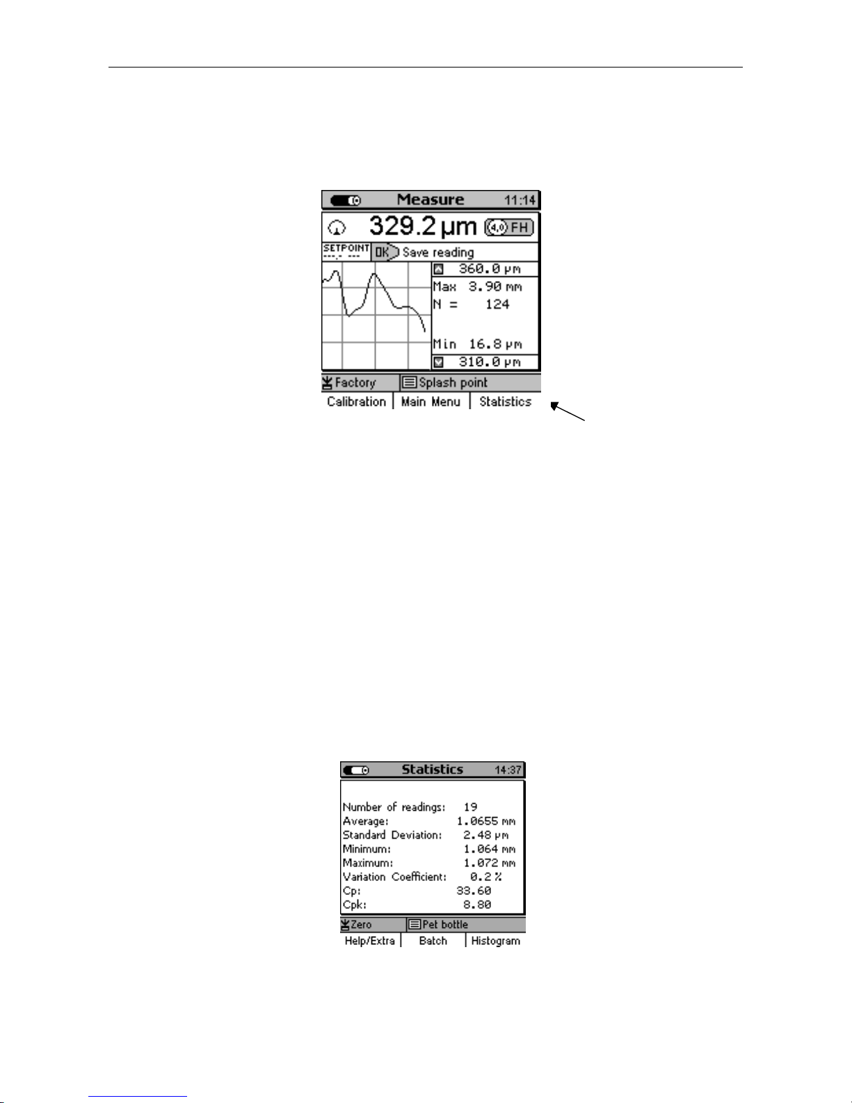
4.3.1 Measure Mode – Numerical Screen..................................................................................13
4.3.2 Measure Mode –Graphics Screen with MiniTest 7400 FH ..............................................14
4.3.3 Statistics Screens...............................................................................................................14
SER MENU ..............................................................................................................................15
4.4 U
4.4.1 U
4.4.2 N
4.4.3 A
SER PREFERENCES...............................................................................................................15
UMERICAL ENTRIES .............................................................................................................16
LPHANUMERICAL ENTRIES (ON MINITEST 7400 FH)...........................................................16
5. MEASURE MODE......................................................................................................................17
MPORTANT NOTES ON THICKNESS MEASUREMENT..................................................................17
5.1 I
5.1.1 Limitations to magneto-static thickness measurement......................................................17
5.2 BATCH CONFIGURATION / NECESSARY SETTINGS.....................................................................17
5.2.1 Batch .................................................................................................................................17
5.2.2 Target Ball Size.................................................................................................................18
5.2.3 Data Logging Mode..........................................................................................................18
5.3 PREPARING MEASUREMENT......................................................................................................18
5.3.1 Calibration........................................................................................................................18
5.3.2 Measurement without Sensor Stand..................................................................................19
5.3.3 Using the Sensor Stand.....................................................................................................19
5.4 TAKE READINGS .......................................................................................................................19
5.4.1 Measurement without Sensor Stand..................................................................................19
5.4.2 Using the sensor stand......................................................................................................20
5.4.3 Delete Readings ................................................................................................................20
TORING READINGS INTO STATISTICS MEMORY.......................................................................20
5.5 S
5.5.1 Data Logging Mode..........................................................................................................20
5.5.2 Manual Data Storage........................................................................................................21
© ElektroPhysik MiniTest 7200 FH / MiniTest 7400 FH
2
Page 3

Contents
5.5.3 Automatic Data Storage (Auto).........................................................................................21
5.5.4 Storing Minimum Reading................................................................................................21
5.5.5 Storing Maximum Reading................................................................................................21
5.6.1 Correct Sensor Position....................................................................................................22
5.6.2. Incorrect Readings through tilting of the Sensor.............................................................22
5.6.3 Incorrect readings through Blocked Target Ball..............................................................23
5.6.4 Air gap...............................................................................................................................23
5.6.5 Measuring material with ferruginous particles................................................................23
6. CALIBRATION...........................................................................................................................24
6.1 G
ENERAL REMARKS ON CALIBRATION .....................................................................................24
ALIBRATION METHODS............................................................................................................25
6.2 C
6.3 H
OW TO CALIBRATE ..................................................................................................................26
6.3.1 Factory Calibration ..........................................................................................................26
6.3.2 Zero only...........................................................................................................................26
6.3.3 Multi-point calibration (Zero + 1 to 4 point(s) )..............................................................27
ELETE CALIBRATION PO INT ....................................................................................................28
6.4. D
6.5 C
ALIBRATION ERROR SOURCES ................................................................................................29
7. DATA STORAGE........................................................................................................................30
7.1 BATCHES...................................................................................................................................30
7.1.1 General..............................................................................................................................30
7.1.2 Batch Data ........................................................................................................................30
ATABASE OF THE MINITEST 7400 FH.....................................................................................31
7.2 D
7.2.1 General Remarks...............................................................................................................31
7.2.2 Tree structure....................................................................................................................31
7.2.3 Create a Directory............................................................................................................31
7.2.4 Create a New Batch ..........................................................................................................32
7.2.5 Select a Batch for Measurement .......................................................................................32
7.2.6 Delete a Batch / a Directory .............................................................................................33
7.2.7 Rename a Batch / Rename a Directory.............................................................................33
8. STATISTICS................................................................................................................................34
TATISTICAL PARAMETERS.......................................................................................................34
8.1 S
8.1.1 Upper and lower specifications limits (USL and LSL).....................................................34
8.1.2 Set Point (Differential Mode)............................................................................................35
8.2 R
EADINGS .................................................................................................................................35
8.2.1 View Readings...................................................................................................................35
8.2.2 Delete Single Readings .....................................................................................................35
8.2.3 Delete all Readings...........................................................................................................36
UMERICAL STATISTICS ...........................................................................................................36
8.3 N
8.4 H
ISTOGRAM ON MINITEST 7400 FH .........................................................................................37
REND DIAGRAM ON MINITEST 7400 FH.................................................................................37
8.5 T
9. DATA OUTPUT / DATA TRANSFER......................................................................................38
9.1 D
ATA PRINT-OUT
........................................................................................................................38
9.1.1 Screen Shot........................................................................................................................39
9.1.2 Print-out a Batch...............................................................................................................39
9.2 T
RANSFER DATA TO A PC.........................................................................................................40
10. MAIN MENU .............................................................................................................................41
10.1 D
© ElektroPhysik MiniTest 7200 FH / MiniTest 7400 FH
ATABASE ..............................................................................................................................41
3
Page 4

Contents
10.2 S
TATISTICS..............................................................................................................................41
10.3 C
10.4 A
ALIBRATION..........................................................................................................................41
CTIVE BATCH .......................................................................................................................41
10.4.1 Batch Properties .............................................................................................................41
10.4.2 Readings..........................................................................................................................42
10.4.3 Configuration..................................................................................................................42
10.4.4 Calibration......................................................................................................................42
10.5 S
ETUP
.......................................................................................................................................43
10.5.1 General Remarks.............................................................................................................43
10.5.2 Display............................................................................................................................43
10.5.3 Date and Time.................................................................................................................43
10.5.4 Data Outputs...................................................................................................................44
10.5.5 User Preferences.............................................................................................................45
10.5.6 Gauge Specifications.......................................................................................................45
11. SPECIAL FUNCTIONS............................................................................................................46
NITIALIZING...........................................................................................................................46
11.1 I
11.2 S
PECIAL FUNCTIONS
..................................................................................................................47
12. QUICK REFERENCE ..............................................................................................................48
13. CARE AND MAINTENANCE.................................................................................................49
13.1 C
ARE.......................................................................................................................................49
13.1.1 Using NiMH storage batteries........................................................................................49
13.2 M
AINTENANCE
.....................................................................................................................49
14. TECHNICAL SPECIFICATION.............................................................................................50
14.1 G
AUGE AND SENSOR SPECIFICATION
14.2 D
ELIVERY SCHEDULE .............................................................................................................52
..........................................................................................50
14.2.1 Thickness gauge MiniTest 7200 FH / 7400 FH..............................................................52
14.2.2 Sensors............................................................................................................................52
14.3 A
CCESSORIES..........................................................................................................................53
15. APPENDIX.................................................................................................................................56
15.1 T
ROUBLESHOOTING
15.2 D
ETECTION OF ERROR SOURCES
TATISTICAL TERMS ...............................................................................................................60
15.3 S
15.4 S
AFETY NOTES........................................................................................................................62
15.5 D
ECLARATION OF CONFORMITY
15.6 A
FTER SALES SERVICE
...................................................................................................................56
(INF
FLAG
)
...............................................................................59
.................................................................................................64
..............................................................................................................65
INDEX...............................................................................................................................................66
© ElektroPhysik MiniTest 7200 FH / MiniTest 7400 FH
4
Page 5

1. Introduction
Designed for non-destructive thickness measurement, the portable MiniTest 7200 / 7400 FH
measuring systems are suit able for in the field or laborator y use. Working on the mag neto-static
principle, the gauges enable quick and easy measurem ent on non-ferromagnetic m at er ials.
The measuring system consists of a handy sensor, which is connected via a cable to the base and
display unit for visualization and processing of readings. For measur ement , specially treated targ et
balls made of a ferromag netic material are used as a r eference. For measurement , a target ball is
placed on the material to be measured so that the material thickness between target ball and
sensor will be measured. The measuring system comes with sensor stand ( available as an option)
to add additional comfort of handling during measurement.
For documentation a portable data printer is available. The measuring system may also be
connected to a PC for data communication.
For taking reading s, the sensor is placed on the surf ace of the m easuring object, the target ball is
placed on the opposite side of sample. The sensor is placed on the opposite side of sample.
Equipped with a strong perm anent magnet, the sensor at tracts the target ball and holds it exactly
over its sensor tip. W hen moving the sensor, the tar get follows accordingly. The presence of the
target ball will change the magnetic field near the sensor tip. The magnetic field changes according
to the distance between target ball and sensor tip. T he change of mag netic f ield increases with the
distance between target ball and sensor t ip getting smaller and can be taken as a reference for the
material thickness of the sample to be measured. The sensor incorporates a Hall element to
capture the change of magnetic field and to translate it into thickness.
For measuring hollow parts, a target ball is placed into the interior of sample and the sensor is
placed on the opposite side in order to attract the t arget ball exactly over the sensor tip. For taking
readings, the sensor is moved over the surface of sample. For measuring sheets, the sensor is
placed on the surface of sheet and t he target ball is placed near the sensor on the opposite side of
sheet. The target ball will automatically center on the correct measuring position and the
measuring processes can be started.
For measuring large-sized parts, the sensor can be guided manually over the sample to be
measured. For measuring small part s, it is recommended to use the sensor stand supplied with the
sensor.
Suitable for use in industrial production areas, the measuring systems MiniTest 7200 / 7400 FH
measure hollow parts, containers and sheet material of all kinds such as bottles, cans, inject ions
moldings, car bodies, glass, SMC components etc made of non-magnetic (non-f er r it e) m at erials.
© ElektroPhysik MiniTest 7200 FH / MiniTest 7400 FH
5
Page 6
2. First Steps
This section refer s to persons to use the gauge for the first time. This section explains the main
features of the gauge and how to take readings.
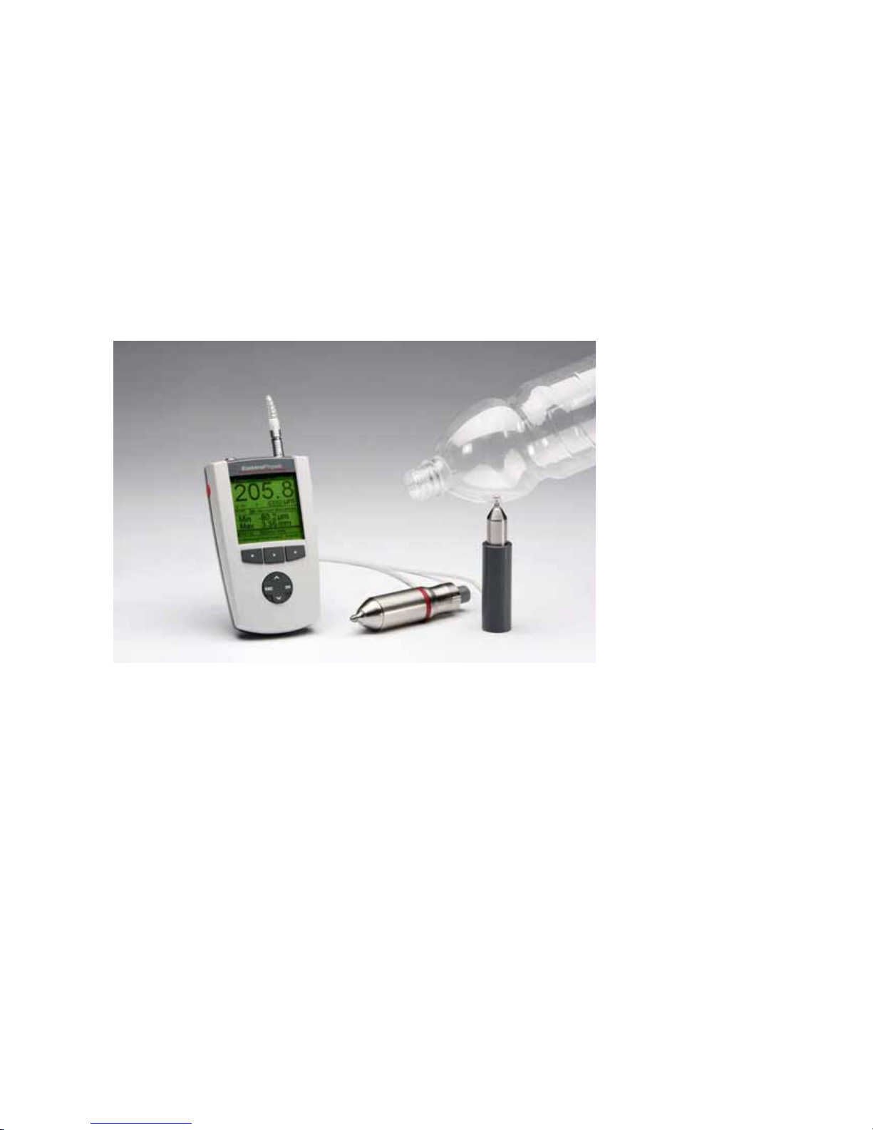
2.1 Insert Batteries and connect Sensor
a) Take gauge and batteries from the carrying case.
b) Push the battery compartment lid at the gauge bottom in arrow direction (as shown below)
c) Inser t bat teries into the battery compartment. Respect polarities (as shown below).
d) Close lid.
b) c)
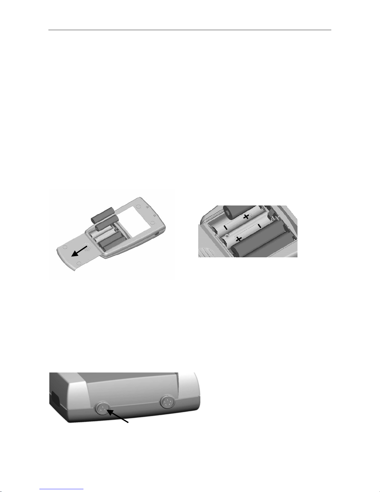
e) Take requested sensor (FH4 or FH10) form t he carrying case. Plug sensor into the sock et on
top of the base unit (as shown below). Make sure the nib of plug is correctly inserted into the
guide way of socket. The red mark ing at t he probe plug must be positioned correctly to the red
marking at the sensor plug .
f) Fully engage the sensor plug into the sensor sock et t o t he stop.
Sensor Socket
© ElektroPhysik MiniTest 7200 FH / MiniTest 7400 FH
6
Page 7

2.2 Switch ON and Take Readings
2.2.1 Setting language
This setting can be made at initial use or as requested at any time (see section 11.1)
Press the red ON/OFF button on the left side of gauge and ESC simultaneously to switch on and to
go to initialization menu.
1. A banner appear s with a language option.
User arrow keys ↑↓ to go to your requested language option.
Press OK to confirm or ESC to abor t.
2. On display appears “Total Reset”. A Total Reset restores factory settings. To abort Total
Reset, press Function key “No” (section 11.1)
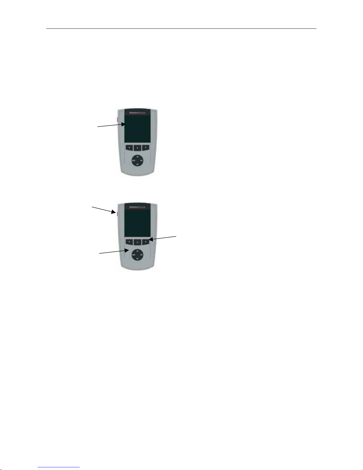
a) Start Screen appears showing company logo, gauge version
and sensor type that is currently connected (see illustr. on the
Flashing antenna symbol if sensor is
connected
left.
b) After approx. 2 seconds, the gauge switches automatically into
measure mode and is ready to take readings. The Measure
Screen will appear without any reading being shown.
c) At initial switch-on the gauge is in “Direct Mode“ (see section
7.1.1). For this mode, the factory calibration is preset (for more
detailed information on “Calibration” topics please refer to section
6). The Status Line provides informat ion on the active calibration
method and the active batch (MiniTest 7400 FH) Please check
whether the target ball size as adjusted mat ches your application
(for more det ails on targ et ball size pleaser refer to sect ion 5.2.2
“Target ball size”).
Target ball diameter, hiere: 4.0 mm.
Selected calibration mode, here:
Zero calibration
© ElektroPhysik MiniTest 7200 FH / MiniTest 7400 FH
Active batch, here: Pet bottle
(only with Minitest 7400 FH)
Status line
7
Page 8

d) The factory calibration is for q uick and easy measurement when larger measuring errors are
acceptable. For other calibration methods please refer to section 6.2.
e) For measurement, please use the sensor st and supplied with the gauge. Place the measuring
object on the sensor. Place the target ball on the opposite side. For measuring hollow parts,
place the ball inside the sample. Equipped with a strong permanent magnet, the sensor attracts
the target ball and holds it exactly over its sensor tip. Hold t he measuring object in rectangular
position to the sensor and move it smoothly over the sensor. Press OK to store the reading into
memory. Press Function key “Statistics” to view readings and the numerical st at istics.
For measuring large-sized sheeting material or large hollow parts, place the senor on the
surface of sample. The t arget ball is placed on the opposite side near the sensor. Keep the
sensor in rectangular position to the surface and move it across the surface of sam ple.
© ElektroPhysik MiniTest 7200 FH / MiniTest 7400 FH
8
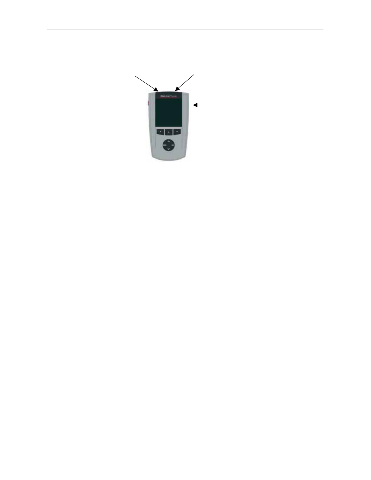
Page 9
Large backlit display for easy reading of
measuring values, statistical data, histog ram and
3. Description of the measuring system
3.1 Basic unit
3.1.1 General Remarks
Graphics display
160 x 160 Dots
3.1.2 Operating keys
trend diagram.
Robust scratch resistant plastics housing.
ON/OFF button
Command and
navigation key
Function keys
block
Use the ON/OFF button to switch the gauge ON or OFF. If you press ON/OFF butt on and ESC
simultaneously, the initializing procedure will be perform ed ( for more details please refer to section
11.1).
The Function keys may assume different functions according to the menu being active. Their
current properties are displayed in the line upper to the Function keys.
The command and navigation key block may also assume different functions:
-
Press OK to confirm settings, store values or select menu items.
-
Press ESC to abort actions or to quit submenus.
-
Use ARROW k eys to navigate through the menu or change sett ings.
-
If the alphanumerical block has been activated, OK and ESC keys also assume navigation
functions.
The Function keys and the command and navigation k ey block may be backlit on request. This
adds additional comfort in poor light condit ions ( for more details please refer t o section 10.5.2)
© ElektroPhysik MiniTest 7200 FH / MiniTest 7400 FH
9
Page 10
Press the “Help” Function key for calling the context-or ient ed on-line “Help“.
3.1.3 Sockets and interfaces
Multi-purpose socket
Sensor socket
IR Interface
The basic unit features a sensor socket for connecting the FH 4 or the FH 10 sensor. The multipurpose socket is used for connecting the mains unit, the foot switch, the alarm device or the
RS232 interface cable.
3.1.4 Power supply
3.1.4.1 Batteries and storage batteries
Both models, MiniTest 7400 FH and MiniTest 7200 FH, are powered by a set of four alkalinemanganese cells, 1.5V, AA LR6 size (Batteries included in the standar d supply schedule.) .
As an alternative, both models may be operated on rechargeable NiMH (type AA-HR6) storage
batteries or via a power supply unit (available as an option). Please use only products as
recommended by ElektroPhysik (See section 14.3, Accessories).
If you wish to use the storage batteries, they must be recharge using the external charger unit
(available as an option). Please also refer to section 13.1 “Care and maintenance” for more details.
Note:
• Remove batteries or storage batteries from the instrument if you are not going to use it for a
longer period of time.
• The battery symbol on display indicates the battery state.
• For field use, replacement batteries should be m ade available.
• Erratic readings due to low battery voltage do not occur because the g auge switches off or
does not switch on if the battery is too low.
© ElektroPhysik MiniTest 7200 FH / MiniTest 7400 FH
10
Page 11

• Used or defective batteries or storage batt er ies m ay contain hazardous substances and
must be disposed according to the legal provisions of your count r y.
3.1.4.2 Power supply unit
For mains operation, the power supply unit must be used. If oper at ed via the power supply unit,
batteries should be inserted to supply the internal time clock, otherwise, after approx. 1 minute, the
settings of the real-tim e clock will go lost as soon as supply from the mains is cut.
The power supply unit comes with two different adapter plug versions ( Eur o and US plug). If the
power supply unit comes with an adapter plug connected that does not match your socket, sim ply
change the adapter plug accordingly.
Simply remove the adapter from the power supply unit and fix the ot her one as r equired.
Note:
The adapter has not been designed for frequent change.
3.2 Sensors FH 4 and FH 10
3.2.1 General Remarks
In this new SIDSP (Sensor integrated digital signal processing) procedure, all necessary
measuring signals are created and complet ely processed in the sensor itself. Only the completely
processed digital readings are transferred to the base unit for display, statistical evaluation and
data storage. Unlike the comm only used analog procedures, the new SIDSP procedure excludes
any error influences on the measuring data during transfer over the probe cable. The result is a
measuring accuracy and constancy of readings that has been unmatched so far. T he complete
sensor technique is integrated into a robust stainless-steel housing.
3.2.2 Sensor Models
Two sensor models are available:
-
FH 4 sensor to cover the 0 …4 mm range
-
FH 10 sensor to cover the 0…10 mm range.
Both sensors feature a wear-resistant sensor tip most suitable also for hard materials such as
glass, for instance.
© ElektroPhysik MiniTest 7200 FH / MiniTest 7400 FH
11
Page 12

3.2.3 Sensor Stand
Both sensor types come with a spring-loaded V-grooved sensor stand. The use of the sensor stand
ensures increased reproducibility of readings by adding stability of t he sensor dur ing measurement
so that even small parts can be measured without problems.
© ElektroPhysik MiniTest 7200 FH / MiniTest 7400 FH
12
Page 13

Power supply indicator
Adjusted set point
CALIBRATION MODE
Number of readings
function key
ties
are indicated in the line above the
4. The User Menu
4.1 General Remarks
4.2 Switch-ON / St art Screen
At switch on, the company logo, gauge version and type of sensor being connected appear on
display.
After approx. 2 seconds the gauge switches to the m easur e scr een of the last batch that was
active before the gauge was switched off.
4.3 Measure screen /Statistics screens
Readings can be displayed numerically only or numerically combined with a diagram (only with
MiniTest 7400 FH)
4.3.1 Measure Mode – Numerical Screen
Time clock
Current reading
Target ball size and measuring unit
Minimum reading
Maximum reading
© ElektroPhysik MiniTest 7200 FH / MiniTest 7400 FH
The current
function keys.
Active batch (MiniTest 7400FH only)
Status line
proper-
13
Page 14
Power supply indicator
Reading
NAME OF ACTIVE BATCH
⇑
UPPER LIMIT
CALIBRATION METHOD
REAL
-
TIME TREND
Set point
function key
ties
are indicated in the line above the
STATUS LINE
function key
ties
are indicated in the line above the
Power supply indicator
Process capability,
cp and cpk
4.3.2 Measure Mode –Graphics Screen with MiniTest 7400 FH
Time clock
Target ball size, measuring unit
DATA LOGGING MODE
MAX = MAXIMUM READING
N = NUMBER OF READINGS
MINIMUM READING
⇓
LOWER LIMIT
The current
function keys.
proper-
For setting the Real-Time Trend display option, select “Act ive Batch” form the Main Menu. Press
OK to confirm. Select “Configuration” from the Batch Menu and press OK to confirm. Use the arrow
keys to move to the “Graphics” option. O N or OFF is highlighted. Use arrow keys to make your
selection and press OK to confirm or the “ESC” navigation button to restore pr evious setting and to
go back to the previous menu level.
To take full advantage of the real-time trend it is necessar y to t oler ance lim its (see also section
8.11 „Upper specification limits (USL) and lower specification limits (LSL)“.
4.3.3 Statistics Screens
Time clock
,
Selected calibration mode
© ElektroPhysik MiniTest 7200 FH / MiniTest 7400 FH
The current
function keys.
Active batch
(MiniTest 7400 FH only)
proper-
14
Page 15
4.4 User Menu
The numerous MiniTest FH 7400 / 7200 features can be accessed via the different menus that are
divided into submenus.
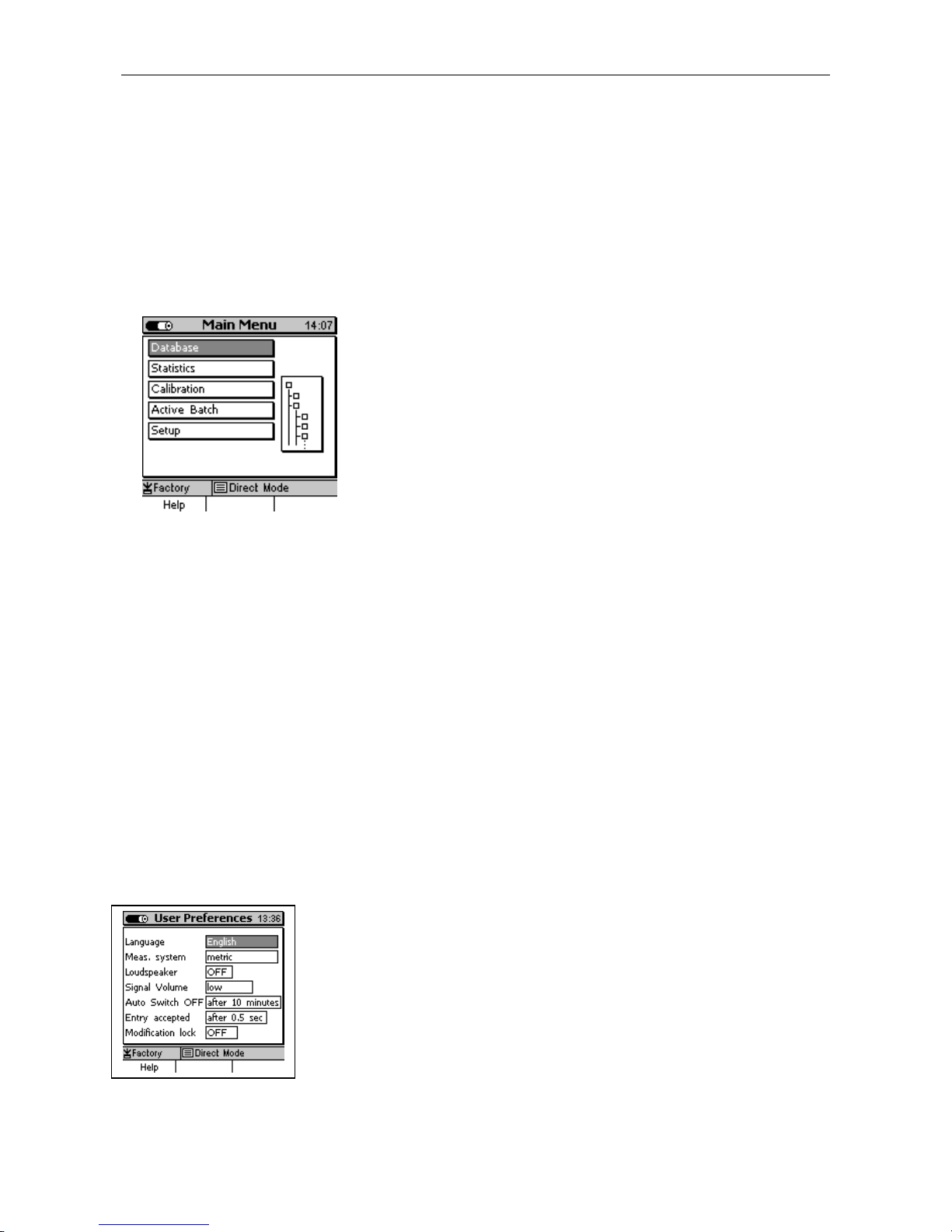
Press the Function key “Main menu“ in order to get access to the main menu.
Select an item from the Main Menu (e.g. Database) and pr ess OK to confirm. You will go to a
submenu. Use the arrow keys to select the requested it em and press OK to confirm.
To go back to the previous menu level press ESC.
According selected submenu you can
-
View settings (e.g. Gauge specs = Gaug e specifications in the Setup Menu)
-
Select preset parameters (e.g. 100% brightness from the Display Menu)
-
Make numerical or alphanumerical entries (e.g. Ent er a dir ectory name in the database / new
directory option).
4.4.1 User Preferences
Use the arrow keys to select your requested menu item, e. g. Language.
Press OK to confirm. T he cur r ent selection will be highlighted. Use the
arrows to select the requested parameter ( e. g. English) and press OK to
confirm. To undo your selection, press ESC and you will return t o the
previous menu level.
© ElektroPhysik MiniTest 7200 FH / MiniTest 7400 FH
15
Page 16
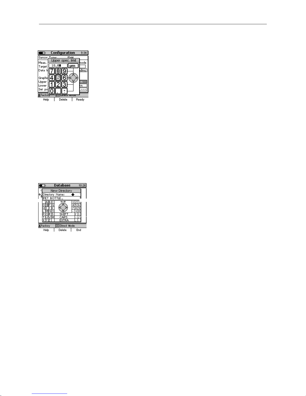
4.4.2 Numerical Entries
As soon as the alphanumeric block is activated, ESC and OK will
assume navigation functions to the left or right. Choose your character
by placing the cursor over the requested character. After a certain period
of time, the entry will be accepted automatically without the need to
confirm. This period of tim e can be specified under User Pref erences in
the “Entry accepted” option. See also section 10.5.5 for further
reference. Complete your entry by pressing Function key “Ready” and
then confirm “Save changes?” by pressing OK.
4.4.3 Alphanumerical Entries (on MiniTest 7400 FH)
For alphanumerical entries you can use as many as 15 characters for
entering a name. ESC and OK assume navigation funct ions to the left or
right. Choose your character via the alphanumerical block. Your
selection will be automatically accepted after the previously specified
period of time. This period of time can be set under User Pref erences in
the “Entry accepted” option. See also section 10.5.5 for further
reference. Complete your entry by pressing Function key “Ready”.
Complete your entry by pressing Function key “Ready” and then confirm
“Save changes?” by pressing OK.
© ElektroPhysik MiniTest 7200 FH / MiniTest 7400 FH
16
Page 17

5. Measure Mode
5.1 Important Notes on Thickness Measurement
Make sure that the operator has been properly instructed regarding the use of thickness gauges
and has basic knowledge of the specific req uir ements for measurement of the application. The
operator should have basic knowledge of the following:
• Selection of a measuring device suitable for his application
• Fundamentals on the magneto-static m easur ing principle
• Influences on the magnetic f ields t hr ough the surrounding field
• Influence of the surf ace pr oper t ies of the material to be tested (roug hness, build-up on the
surface)
• Statistical evaluation of measuring series
• Gravity influencing the reference ball
5.1.1 Limitations to magneto-stati c t hi ckness measurement
The information obtained f rom thickness measurements according to the magneto-static principle
only refer to those parts of the test object that have been covered by the magnetic sensor . For t hat
reason, be careful to draw conclusion on other parts of the measuring object that have not been
covered by the sensor during measurement. In g eneral, such conclusions are only admissible if
comprehensive experience and approved methods of statistical data acquisit ion ar e available.
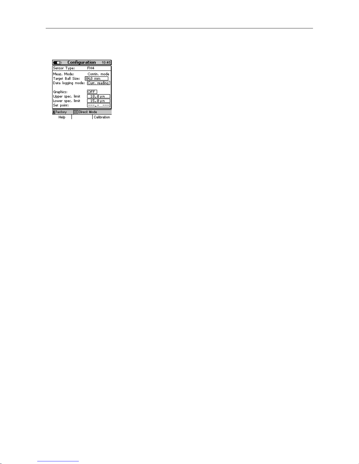
5.2 Batch Configuration / Necessary Settings
Before taking reading s, it is necessary to make a few settings in the Configuration menu. The
Configuration always refers to a cer t ain m easuring series (Batch).
5.2.1 Batch
-
You can continue to take readings in the active batch
-
You can create a new batch (only with MiniTest 7400 FH model)
-
You can choose an exiting batch from the database (please r efer to section 7.2).
© ElektroPhysik MiniTest 7200 FH / MiniTest 7400 FH
17
Page 18
According to sensor type and the shape of measuring object, a
Use arrow keys to move to “Target Ball” size and press OK. Use arrow
keys to adjust the requested tar g et ball size. Press O K to confir m your
setting or press ESC to undo your setting. If you undo, you will
get ball setting option and go back to the previous
5.2.2 Target Ball Size
suitable target ball must be set. This can be made in the Configuration
menu, menu item “Targ et ball” (also refer to section 6 “ Calibr at ion” .
automatically quit tar
menu level.
5.2.3 Data Logging Mode
In the data logg ing mode you can specif y how you wish readings to be stored in memory. Several
modes are available:
-
manually or via footswitch (Current reading, MIN, MAX)
-
Automatic (Auto)
Note: For logging data into memory please always proceed as follows: Put the sensor into the
correct measuring position, press ESC. Then readings can be taken.
5.3 Preparing Measurement
Before measurement, the probe must be adapted to the ambient temperature. In case of high
variations in temperature, the targ et ball must be lifted f rom the probe tip at regular intervals (e.g.
every other minute). This is to compensate f or f r equency drif t due to variations in temperature. It is
recommended to switch on the gauge for warming up around 2 to 3 minutes in order to ensure
maximum measuring accuracy.
5.3.1 Calibration
According to your setting of task , you may use different calibration methods. Measuring accuracy
depends on the selected calibration method. Please refer to section 6 for more details on this
issue.
There are three calibration methods available:
-
Factory
-
Zero only
-
Multi-point calibration (Zero + 1 to 4 Point(s)
© ElektroPhysik MiniTest 7200 FH / MiniTest 7400 FH
18
Page 19
5.3.2 Measurement without Sensor Stand
For measuring large-sized parts, t he sensor can be guided manually over the measuring sample.
For measuring thick samples (6 m m and thicker) make sure to k eep the sensor in vertical position
to the sample. When holding the sensor in horizontal position, due to the influence of gravity on the
steel ball, the readings will be higher than the actual t hickness.
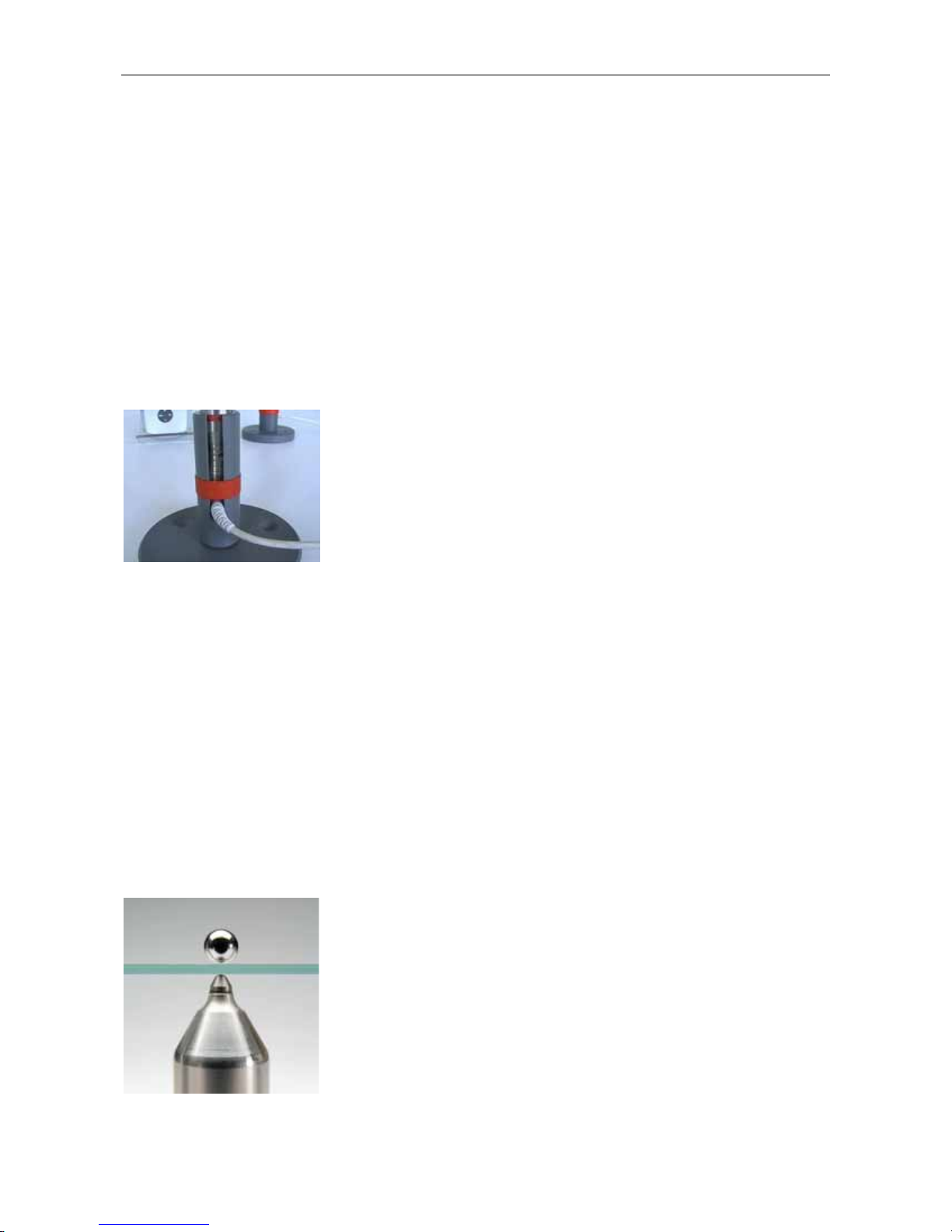
5.3.3 Using the Sensor Stand
For measuring small part s, bottles or other cylindrical bodies the sensor stand (supplied with the
sensor) and a footswitch (available as an option) should be used.
Put the sensor into the stand and secure with the red sensor stand
retaining ring.
5.4 Take Readings
5.4.1 Measurement without Sensor Stand
For measurements on large-sized sheeting m aterial or large hollow parts, place the sensor onto
the surface of the object to be measured. Place an appropriate targ et ball on the opposite side of
object near the sensor. The t arget ball will be attr acted by the strong permanent mag net of sensor
and be positioned centrally just opposite of the sensor t ip. Keep the sensor in right-angle posit ion
to the object to be measur ed and scan continuously over the surface. For storing readings, please
refer to section 5.5.1.
© ElektroPhysik MiniTest 7200 FH / MiniTest 7400 FH
19
Page 20

5.4.2 Using the sensor stand
If you are using the sensor stand, position the sample on the sensor tip and keep it in r ight-angle
position to the sensor. Place the appropriate tar get ball on the opposite side of obj ect. Make sure
to keep the right -angle position while moving the object continuously over the sensor. For stor ing
readings, please refer to section 5. 5.1.
When measuring small hollow parts such as bottles e.g., put the target ball inside the object and
place the object onto the v-grooved device of sensor stand. Turn the object unt il the target ball is
centered directly over the sensor tip. Then move the object continuously over the v-groove of
sensor stand. For storing readings, please r efer to section 5.5.1.
5.4.3 Delete Readings
Please refer to section 8.2.2 “Delet e Single Readings“.
5.5 Storing Readings into Statistics Memory
5.5.1 Data Logging Mode
During measurement, readings can be stored into memory manually or automatically. Data in
memory will be used for statistics.
The following storing options are available:
-
Storing the current reading manually or automatically
-
Storing the minimum reading (only manually)
-
Storing the maximum reading (only manually).
The Data logging mode can be specif ied in the “ Conf igur ation” submenu. Use ar row keys to select
the Data logging mode option and pr ess OK to conf irm. You can chose f rom t he following setting
options:
-
Curr. reading (Current reading)
-
Auto
-
Max
-
Min
Make your selection and press OK to confirm. If you wish to undo your setting (before OK has
been pressed) press ESC and the gauge will return to t he pr evious menu level.
© ElektroPhysik MiniTest 7200 FH / MiniTest 7400 FH
20
Page 21

5.5.2 Manual Data Storage
During the measuring procedure, cur rent readings can be stored manually into the active batch by
pressing OK or by actuating a foot switch. For t his option set Data logging mode to “ Curr . reading”.
5.5.3 Automatic Data Storage (Auto)
Auto option
In the auto mode, readings will be stored automat ically during the measuring procedure as soon as
you press OK. To st op the automatic data storage press O K again. If a footswitch is connected,
readings are stored as long as the f oot switch is actuat ed.
Before starting the automatic data storage make sure the sensor is placed in the correct measuring
position. Make sure to st op the automatic data storage BEFO RE t he sensor has left the measuring
position. This is to avoid errat ic readings to be stored into memory that m ight occur when putting
the sensor to or lifting it from the sample.
After setting the Data logging option to the Auto option, a Logging rate option will appear. The
logging rate defines t he time intervals at which data will be stored into memory (1, 2, 5, 10 or 20
readings per second). For slow measurement scans, a low logging rate should be set, for quick
scanning, the logging rat e should be set to a higher rate.
5.5.4 Storing Minimum Reading
In the Minimum option, m inimum r eadings will be stored to t he active batch by pressing OK during
measurement or by activating a foot switch.
To set Data logging mode t o the MIN option, go to the Configuration submenu and select Data
logging mode. Use arrow keys to select MIN and press OK t o confirm. Please note: The minimum
reading can also be stored even after the sensor has been lifted from the sample.
5.5.5 Storing Maximum Reading
In the Maximum option, maximum readings will be stored to the active batch by pressing OK during
measurement or by activating a footswitch.
To set Data logging mode t o the MAX option, go to the Configuration submenu and select Dat a
logging mode. Use arrow keys to select MAX and press OK to confirm.
Important note:
-
Make sure to put the sensor into the correct measuring position and to press ESC before
storing the Maximum reading into memory.
-
© ElektroPhysik MiniTest 7200 FH / MiniTest 7400 FH
OK must be pressed BEFORE the sensor is moved from its measuring position.
21
Page 22

ned correctly in perpendicular position
to the sample. The reading will therefore be hig her t han the actual
5.6 Error Sources during Measurement
After calibrating the gauge according to your application and appropriate target ball size, the gauge
is ready for measurement.
The readings will be correct as long as you measure within the range as specif ied for this target
ball. The target ball is placed on one side of the sample to be measured and will be attracted by
the sensor tip on the other side of the sample. The targ et ball serves as a reference to the sensor.
What is being m easur ed is t he distance between sensor and target ball.
Make sure to place both, the sensor tip and the targ et ball cor r ectly onto the sample. Both must be
in good contact with the surface of sample. Otherwise erratic readings (higher readings) might
occur. Make sure to keep the sensor in perpendicular position while moving it over the sample. The
target ball on the other side must be freely movable.
5.6.1 Correct Sensor Position
The picture illustrates the correct position of sensor tip and steel
ball. Make sure to keep the sensor tip perpendicular to the
surface of sample.
5.6.2. Incorrect Readings through tilting of the Sensor
Error source:
The sensor tip is not positio
thickness.
Remedy:
Make sure to keep the sensor in perpendicular position to t he
sample. If necessary, use the sensor stand.
© ElektroPhysik MiniTest 7200 FH / MiniTest 7400 FH
22
Page 23

The target ball has got stuck through a bulge, e.g. inside the
5.6.3 Incorrect readings through Blocked Target Ball
Error source:
sample. It is out off t he cor r e ct m easur ing position.
Remedy:
Move the sample in order to release the target ball.
5.6.4 Air gap
Error source:
Due to the shape of sample, an air gap is between
target ball and measuring object. The reading will be
higher than the actual thickness.
Remedy:
If the tar get ball is too large, use a smaller one. If the
sensor is not in good contact, change measuring
position and use a smaller target ball, if necessary.
5.6.5 Measuring material wi t h f errugi nous part i cl es
Ferruginous particles in the material to be measur ed m ay lead to err atic readings because the
ferruginous particles may inf luence t he m easur ing signal. This will lead to readings smaller t han
the actual thickness.
© ElektroPhysik MiniTest 7200 FH / MiniTest 7400 FH
23
Page 24

6. Calibration
Calibration is made in the batch being active and will always refer to this batch, i. e. each batch has
its own calibration. Before calibration, an appropriate target ball diameter must be set in the
Calibration menu. Please refer to section 5.2.2 “Targ et ball size”.
There are two options to go to the Calibrat ion menu:
-
from the Main menu choose Calibration
-
from the Measure Mode menu press Calibration function key.
For selecting an appropriate targ et ball, the following aspects should be taken into consideration:
-
minimum radius of sample to be measured
-
maximum thickness to be measured
-
required measuring accuracy
Sensor Target ball to
be used
Min. Internal
radius of sample
Measuring
range
Recommended
measuring range
FH 4 Ø 1.5 mm 0.75 mm 0 ... 1.5 mm 0... 1.5 mm
FH 4 / FH 10 Ø 2.5 mm 1.25 mm 0 ... 2.5 mm 1... 2.5 mm
FH 4 / FH 10 Ø 4.0 mm 2.0 mm 0 ... 4.0 mm 2... 4.0 mm
FH 10 Ø 6.0 mm 3.0 mm 0 ... 10 mm 3... 6 mm
FH 10 Ø 9.0 mm 4.5 mm 0 ... 10 mm 6... 10 mm
6.1 General Remarks on Calibration
For achieving maximum accuracy, please observe the following calibration instructions:
• Make sure to keep off str ong magnetic fields from t he sensor during measurement.
• Keep away from any ferromagnetic metal par t s in a safety distance of at least 30 cm.
• It is recommended to switch on the gauge for warming up around 2 to 3 minutes befor e
starting calibration procedure.
• Make sure the sensor tip, target balls and calibrat ion st andar ds ar e clean. Any foreign
matter may lead to erratic readings.
• For maximum accuracy of calibration and later measurements, choose t he thickness of
calibration standard within the same thickness range as the later measuring sample.
• In some cases it may become necessary to recalibrate if a new target ball is used (also if it
has the same diameter as the previously used one). To be sure, check calibration in
© ElektroPhysik MiniTest 7200 FH / MiniTest 7400 FH
24
Page 25

measuring mode by putting the matching precision standard with the appropriate target ball
on the sensor.
• Please note that large target balls will compress soft material more t han sm all t arget balls.
Please note:
If the gauge switches of f during the calibration procedure due to low battery voltage, calibration
must be repeated after installing fresh batteries.
Please note:
Each time the target ball is removed f r om t he sensor tip in a distance of more than 30 mm, t he
gauge will automatically be adjusted to the inf init e r ange. Any possible drift influences (e. g.
through variations in temperature) will be extensively compensated. The m or e often the target ball
is removed form the sample, the mor e often compensation will take place so as to increase
measuring accuracy.
For that reason it is recommended to lift the target ball f r om the sensor tip at least every three
minutes. A message will appear on display accordingly to remind you to repeat inf init e setting
(“Refresh infinite Value !!!).
To ensure measuring accuracy, check calibration after one hour of use of t he gauge and
recalibrate if necessary.
6.2 Calibration methods
According to your setting of task, you may use different calibration met hods. Measuring accur acy
depends on the selected calibration method. The following calibration methods are available:
-
Factory calibration.
This calibration method is suitable for quick and simple measurement and if lar ger
measuring errors are admissible as compar ed t o zero calibr at ion.
-
Zero only (zero point calibration).
This method is for quick calibration with a medium measuring accuracy.
-
Multi -point calibration (Zero + 1 to 4) Calibration standard(s).
In most cases a Two-point calibration (Zero + one standar d) will be suf ficiently good as
far as calibration is made in the range of thickness to be expected. Further calibrat ion
points are recommended if measurem ent will be over a larger thickness range and if
accuracy requirements are high.
© ElektroPhysik MiniTest 7200 FH / MiniTest 7400 FH
25
Page 26

6.3 How to calibrate
For zero point calibration, the zero standards supplied with the gauge
with the matching target balls. Make sure
always first to place the target ball into the zero standard. Then put
both together onto the sensor. Wait for the sound to bleep, remove the
For mean calculation it is recommended to repeat the procedure
several times. (To g et reasonable values it is always recommended t o
take several readings and to have the mean calculated). Pr ess OK to
Using the sensor stand will add additional comfort during the calibration procedure. For more
details please refer to section 5.3.3.
For all calibration methods the following applies:
-
To call the Calibration menu from Measure mode menu, press the Calibration function key.
-
Use the arrow keys to go to “Targ et Ball”. Press OK to confirm. Use arrow keys to adjust to
the requested target ball size. Pr ess O K t o confirm.
-
Use arrow key to go to “Calibration Mode”. Press OK to confirm and use arrow keys to
make your selection. Press OK to confir m .
-
6.3.1 Factory Calibration
Use arrow keys to select “Factory“. Press OK to conf ir m. The gauge is
ready for measurement.
6.3.2 Zero only
Use arrow keys to select “Zero only“. Press OK to confirm.
must be used together
precision standard and keep it in a distance of at least 30 mm.
confirm.
A ticked box right to “Zero“ will confirm successful calibration.
Now the gauge is ready for measurement.
© ElektroPhysik MiniTest 7200 FH / MiniTest 7400 FH
26
Page 27

Zero calibration standard wit h t arget bal l put on it
6.3.3 Multi-point calibrat i on ( Zero + 1 t o 4 poi nt ( s) )
For multi-point calibration you must firs t carry out a zero point calibration. T he precision standards
must be used (1 to 4 as requested) to calibrate for the further calibration points. The precision
standards have different thick ness values.
1. In most cases a Two-point calibration (Zer o + one standard) will be sufficiently good as far
as calibration is made in the range of thickness to be expected.
2. Further calibration points are only necessary if measurement will be made over a larger
thickness range and if accuracy req uir em ents are high.
Now use arrow keys to select “Zero + 1 point” calibration. Press O K
to confirm. Carry out zero calibrat ion as described under 6.3. 2. Then
use arrow keys to select “Calibr. Point 1”, press OK to confirm.
© ElektroPhysik MiniTest 7200 FH / MiniTest 7400 FH
Please always use one of the precision standards supplied with the
sensor. Make sure first to place the target ball on the precision
standard. Then place t he precision standard toget her with the target
ball onto the sensor. W ait for the signal tone to sound and lift the
precision standard more than 30 mm from the sensor. For calculation
of average repeat several times.
In the “CAL = “ field, the calibration mean value will be shown
which has been calculated form the set of single readings you have
taken. If this value is the same as specified on the precision
standard, press OK to complete the calibration procedure. If not,
please use arrow keys to correct the value as requested.
27
Page 28

In the alphanumerical input field, you can enter the t hickness of the
precision standard along with the unit. ESC and OK assume
navigation functions to the left or right. You can select the requested
character via the numerical block. Your selection will be
automatically accepted after the specif ied period of tim e. This period
of time can be specified in the Setup menu. Chose User Preferences
and select “Entry accepted” (see also section 10.5.5). Com plete your
entry by pressing Function key “Ready”. To store your setting, press
OK. Then press OK again to quit .
For more calibration points repeat procedure as necessary. The current state of calibration is
indicated in the calibration check box in the calibration menu. Ticked boxes will mark successful
calibration points.
After successful calibration of the last calibration point, the gaug e is ready for measurement.
6.4. Delete calibration point
Use arrow keys to move to the calibration point to be deleted.
Press “Delete” Function key and press OK to confir m or ESC to abort. Pressing “Delete” Funct ion
key a second time will remove the (X) from the check box. If you press again “Delete” Function
key, the calibration value will also be deleted.
© ElektroPhysik MiniTest 7200 FH / MiniTest 7400 FH
28
Page 29

6.5 Calibration Error Sources
The following situations may lead to erratic calibration:
Error: Remedy:
Wrong target ball: Select an appropriate target ball suitable for
your measuring sample and the thickness to be
expected.
Adjust to the correct target ball size via the
menu.
Calibration range does not match to the
thickness to be expected:
During calibration, the precision standard has
not been placed correctly on the sensor Tipp.
Calibrate within the thickness range to be
expected.
Make sure to fully engage the precision
standard on the sensor tip.
Calibration error due to changes in temperat ur e Before calibr at ion, the sensor must be adapted
to the ambient temperature. Please wait 30
minutes after switch on before starting
measurement.
Worn or damaged precision standards: Please use new precision standards in
impeccable condition.
Build-up on the sensor tip. Clean sensor tip from metal par t s , dir t par t icles
etc. by using a soft cloth.
© ElektroPhysik MiniTest 7200 FH / MiniTest 7400 FH
29
Page 30

7. Data Storage
7.1 Batches
7.1.1 General
Readings and their statistics will be stored in batches. Batches can be nam ed alphanum er ically
and stored in the database directly or under a certain directory. One batch is firmly installed under
the name “Direct Mode”. This batch cannot be deleted nor can it be r enam ed.
The model MiniTest 7200 FH does not include the database featur e, but it offers one
predefined
measuring batch.
7.1.2 Batch Data
7.1.2.1 Readings
One batch may include as many as 100,000 single readings plus statistics. The model MiniTest
7400 FH offers a maximum of 240,000 values in total.
7.1.2.2 Calibration Values
Calibration always refers to a certain measuring batch. As soon as a measuring batch is called, the
corresponding calibration will become active. The calibration includes the following parameter
settings: diameter of t arget ball, type of calibration and sensor.
7.1.2.3 Other Parameters
The parameters as set in the Configuration submenu such as Data logging m ode, Logging rate,
Graphics (ON/OFF), Upper spec. limit, Lower spec. limit, and Setpoint ref er to a certain batch and
will become valid as soon as this batch is called.
© ElektroPhysik MiniTest 7200 FH / MiniTest 7400 FH
30
Page 31

7.2 Database of the MiniTest 7400 FH
7.2.1 General Remarks
The database includes numerous features for data management. Measuring batches can be stored
in directories and subdirectories. In total, as many as 500 directories may be created in a
maximum of 5 levels. Directories and batches can be named alphanumer ically.
7.2.2 Tree structure
Example for a tree-structured database divided in directories and
batches. At first use of the MiniTest 7400 FH, the database only
includes one batch named “Direct Mode”. You can create other
directories or batches as required.
Note: For creating new directories or batches, make sure to place
7.2.3 Create a Directory
the cursor below
this Direct Mode directory.
Press function key “ Main Menu”. Then select “Database” and press
OK to confirm.
Use arrow down key of the navigation block to place the cursor
below “Direct mode” or, if other directories have already been
created, to the requested posit ion where a new directory should be
created.
This may be below or between directories or batches. Now press
function key “Actions” and press OK to confirm “New Directory”
which is highlighted.
Enter a name in the alphanumerical input field. For more details,
please refer to section 4.4.3 “Alphanum er ical Ent r ies”.
© ElektroPhysik MiniTest 7200 FH / MiniTest 7400 FH
31
Page 32

7.2.4 Create a New Batch
cursor to “New Batch” which is highlighted. Press OK to confirm.
From M easure Menu press function key “Main Menu”. Then select
“Database” and press OK. Use arrow down key of the navigation
block to place the cursor below “Direct mode” or, if other directories
have already been created, to the req uested position where a new
directory should be created. This may be below or between
directories or batches. Now press function key “Actions” and move
Enter a name in the alphanumerical input field. For more details,
please refer to section 4.4.3 “Alphanum er ical Ent r ies”.
After you have entered the bat ch name, the alphanumerical screen
appears. Now you can enter a user name below the batch name
according to the procedure as described above.
After completion of user name input, the confirmation as shown on
the left appears. If you wish to accept the parameters (calibration
and configuration) as set f or the act ive batch for t he new batch to be
created press OK. If you press ESC, preset parameters of the factory
calibration will become valid. Parameter settings can be made in the
“Configuration” submenu. Please refer to section 10.4.3 for more
details.
7.2.5 Select a Batch for Measurement
From Main Menu select “Database”. Use arrow keys to select the
requested batch. Press OK to conf ir m . The data stored under this
batch appear on display. Press OK to switch to Measure Menu.
© ElektroPhysik MiniTest 7200 FH / MiniTest 7400 FH
32
Page 33

7.2.6 Delete a Batch / a Directory
From Measure Menu press function key “Main Menu“ and select
„Database“. Press OK to confirm .
Use arrow keys to select the directory or batch to be deleted. Press
function key “Actions”. Select “Delete” from the “Actions” submenu. A
confirmation appears. Press OK to confirm or ESC to abort.
If you have chosen a directory, the delete action will only delete
empty directories. If the directory includes subdirectories and
batches, these must be deleted previously.
Please note: The batch “Direct Mode” is a permanent part of the
database. It can neither be deleted nor r enam ed. Nor you can assig n
a username to it. However, you can delete readings or statistical
values.
Once you have deleted data they cannot be restored.
7.2.7 Rename a Batch / Rename a Directory
From Measure Menu press function key “Main Menu“ and select
“Database“. Press OK to confirm .
Use arrow keys to select the directory or batch to be renamed. Your
selection will be highlighted. Press function key “Actions”.
Use arrow keys to go to “Rename”. Press OK t o confirm.
On the alphanumerical input field the name to be changed appears.
This name can be changed (see section 4.4.3 “Alphanumerical
Entries”.) This action will not change the usernam e.
© ElektroPhysik MiniTest 7200 FH / MiniTest 7400 FH
33
Page 34

8. Statistics
From Measure Menu press function key “Stat istics“ .
From Main Menu use arrow keys to select “Statistics” and press OK to confirm.
8.1 Statistical Parameters
8.1.1 Upper and lower specificat ions limits (USL and LSL)
Tolerance limits can be set as requested and offer you the following featur es:
-
Readings beyond the specificat ion limits will be indicated by a signal tone and marked in
the statistics.
-
The process capability indices Cp and Cpk will be calculated according to the set
specification limits.
-
In the trend diagram and histog ram, readings lying within the set specification limits will be
highlighted. This range will determ ine the real-t ime trend ( only available with MiniTest 7400
FH).
The specification limits can be set in the “ Configuration” submenu. .
Use arrow keys to go to “Upper spec. limit ” and/ or “Lower spec. limit”
Specify limits and measur ing system (metric/imperial) as requested
via the alphanumerical input field. See also section 4.4.2
“Alphanumerical Entries”.
Complete your setting by pr essing Function k ey “Ready”. The gaug e
will check automatically whether your spec. limits are reasonable.
This is to prevent input er rors such as entering a wrong measuring
unit. Press OK to confirm your chang es.
Spec. limits can be deleted via the function key “Delete”.
Spec. limits can be set before or after readings have been taken.
© ElektroPhysik MiniTest 7200 FH / MiniTest 7400 FH
34
Page 35

8.1.2 Set Point (Differential Mode)
In quality control, it may be interesting to measure the difference between a set point and the
actual thickness. Once you have specified a set point, the difference between this set point and the
actual thickness will be displayed. A set point must be entered BEFO RE storing t he f irst r eading . If
you change a preset set point, the stored reading s m ust be deleted previously.
The set point can be set in the “Conf iguration” submenu. Use arrow keys to g o to “Set point” and
enter a value as requested along with the correct measuring system (metric/imperial) via the
alphanumerical input field. See also section 4.4.2 “Alphanum er ical Ent ries”.
Complete your setting by pressing Function key “Ready”. Set point set tings can be deleted via the
function key “Delete”.
8.2 Readings
8.2.1 View Readings
From Main Menu go to “Statistics”. Press OK and select “Readings” submenu.
From Measure Menu press function key “Stat istics”. Then press function key “Batch” followed by
function key “Readings”.
Use arrow keys to scroll through the batch as requested. Readings will be indicated along with
their current reference number. If spec. limits have been set previously, information is included
whether the readings have been above (>>) or below (<<) the spec. limit.
8.2.2 Delete Single Readings
Erratic readings may be deleted from the list.
Move the cursor to the reading to be deleted.
Press function key “Help/Extra”. Move cursor to “Delete Readings”
and press OK to confirm or press ESC to abor t.
Readings that have been deleted are marked by (X).
© ElektroPhysik MiniTest 7200 FH / MiniTest 7400 FH
35
Page 36

8.2.3 Delete all Readings
x
From Main Menu chose “Statistics“. Use arrow keys to move to
“Delete all readings“. Press OK to confirm.
From Measure Menu press function key “Statistics” followed by
function key “Help/Extras”. Use arrow keys to move to “Delete all
readings“. Press OK to confir m.
To abort, press ESC.
The delete action will delete all readings of the active batch. Batch
name, sensor config uration and calibration for this batch will remain
in memory.
8.3 Numerical Statistics
From Main Menu chose “Statistics“. Use arrow keys to move to “Numerical Statistics”. Press OK to
confirm.
From Measure Menu press function key “Stat istics” .
Number of readings
Average (
)
Standard deviation (s)
Minimum
Maximum
Variation coefficient
Process capability indices Cp and Cpk (if spec. limits have been set).
For more detailed information on statistics please refer to section
15.3.
© ElektroPhysik MiniTest 7200 FH / MiniTest 7400 FH
36
Page 37

8.4 Histogram on MiniTest 7400 FH
From Main Menu chose “Statistics“. Use arrow keys to move to “Histogram“. Press OK to confirm.
From Measure Menu press function k ey “Stat ist ics” followed by function key “Histogram”.
A histogram is a kind of plot that summarizes how data are
distributed. It gives you information on how the production process
might be changed in order to be optim ized.
The limit range is t he gray-highlighted area. See also 8.1.1 “Upper
and lower spec. limits”.
Please note: For a histogram, a minimum number of 5 readings are
required.
8.5 Trend Diagram on MiniTest 7400 FH
From Main Menu chose “Statistics“. Use arrow keys to move to “Trend Diagram“. Press OK to
confirm.
From Measure Menu press function key “Statistics” followed by function key “Histogram”. Then
press function key “Trend”.
A trend illustrates the tendency of reading s so that deviations can be
quickly identified.
The limit range is the gr ay-highlighted-area.
For a trend-diagram, at least 5 r eadings are required.
© ElektroPhysik MiniTest 7200 FH / MiniTest 7400 FH
37
Page 38

9. Data Output / Data Transfer
Both models, MiniTest 7200 FH and MiniTest 7400 FH are equipped with a bi-directional RS232
interface and an infrared interface (IrDA 1.9). Readings and statistics of a batch can be transferred
to a PC or to the MiniPrint 7000 data printer (available as an option).
9.1 Data Print-Out
Data transfer of readings and statistics to the data pr inter MiniPrint 7000 is made via the infrared
interface (IrDA 1.0). Before printing out, go to the Main Menu and select “Setup”. Use arrow keys to
move to “Data Output” and press OK to conf irm. Use arrow keys to select “Infrared (IrDA)”. For
more details, please refer to sect ion 10. 5.4.2.
Readings and statistics may be printed out from all statistical views
such as statistics, batch, histogram or trend (MiniTest 7400 FH).
Press “Help/Extra” Function key from your selected st atistical view.
The Help/Extra window opens (Fig. 1)
Fig. 1
Fig. 2
Select “Print” form t he list and confirm by “OK”.
A “Printing sequence” menu opens (Fig. 2) Move the cursor to the
first item on the list and press OK. Use arrow keys to make your
selection (Fig. 3). The following options are available:
-
Logo (Company logo or other customized logo in graphics
format (160x80 Pixel). For inserting such logo, MSoft 7000
software is required.
-
Name (of batch) / or name (of batch) + date (MiniTest 7400
FH).
-
Operator (with MiniTest 7200 FH Notes-Field only)
-
Statistics (number of readings, Average (x) Standard
deviation (s), Min., Max. Variation Coefficient, Cp and Cpk ) .
-
Measuring Values or Measuring Values + Deleted Values
(see also section 8.2.2).
-
Trend (MiniTest 7400 FH only)
Fig. 3
© ElektroPhysik MiniTest 7200 FH / MiniTest 7400 FH
-
Histogram (MiniTest 7400 FH only)
-
Notes-Field (space for remarks with 5 lines)
-
----- (remains empty)
38
Page 39

Press OK to confirm your selection and go t o the next position on the
printing list and proceed as described above.
The print-out list can also be limited to fewer items (e.g. statistics and
measuring values only, Fig. 4)
Fig. 4
Now align the infrared windows of the MiniTest and MiniPrint 7000.
Press function key “Print” to start t he print-out.
To abort, press “ESC”.
9.1.1 Screen Shot
Please refer to section 11.2 “Special f unctions“.
9.1.2 Print-out a Batch
Please refer to section 9.1 “Data Pr int - out ”
© ElektroPhysik MiniTest 7200 FH / MiniTest 7400 FH
39
Page 40

9.2 Transfer Data to a PC
Before transferring data, go to the Main Menu and select “Setup”. Use arrow keys to move to
“Data Output” and press OK to confirm. Use arrow keys to select “RS232 cable” or “Infrared (IrDA).
Press OK to conf irm. See also section 10.5.4. I f you adjust to RS232, please make sur e to make
the correct settings for baud r at e and t r ansmission protocol.
Readings and statistics may be transferred to a PC from all statistical
views such as statistics, batch, histogram or trend (MiniTest 7400
FH). Press “Help/Extra” Function key from your selected statistical
view. The Help/Extra window opens (Fig. 1)
Select “Print” form t he list and confirm by “OK”.
A “Printing sequence” menu opens. Move the cursor t o the first item
on the list and press OK. The following options ar e available:
-
Name (of batch) / or name (of batch) + date (MiniTest 7400
FH).
-
Statistics (number of reading s, Average (x) Standard
deviation (s), Min., Max. Variation Coefficient, Cp and Cpk ) .
-
Measuring Values or Measuring Values + Deleted Values
(see also section 8.2.2).
-
Operator (with MiniTest 7200 FH Notes-Field only)
-
----- (remains empty)
Press OK to confirm you selection.
Connect the MiniTest FH via the RS232 cable to your computer or
align the infrared windows of your computer or of your IrDA adapter
respectively.
Then press Function key “Send->PC”.
To abort, press “ESC”.
Please note
: The “MSoft 7000 Pro” software recalculates the
histogram and trend diagram (MiniTest 7400 FH oly) and optimizes
© ElektroPhysik MiniTest 7200 FH / MiniTest 7400 FH
their display in graphical format.
40
Page 41

10. Main Menu
10.1 Database
Please refer to section 7.2.
10.2 Statistics
Please refer to section 8.
10.3 Calibration
Please refer to section 6.
10.4 Active Batch
10.4.1 Batch Properties
From Main Menu chose “Active Batch” and press OK to confirm.
Now you can select from the options as shown on the left.
Select “Batch properties” and press OK to conf ir m.
Now you can view:
Batch name (with MiniTest 7400 FH)
Create date,
Modified date
© ElektroPhysik MiniTest 7200 FH / MiniTest 7400 FH
User name.
Press function key “Statistics” to view the statistics of t his batch..
41
Page 42

10.4.2 Readings
10.4.3 Configuration
This menu is for viewing readings.
To view the corresponding statistics, press function key “Batch”
followed by function key “Statistics”. See also section 8.
In this menu you can set the following parameters to define your
batch as requested:
Target ball size (see section 5.2.2)
Data logging mode (see section 5.5)
Logging rate (see 5.5)
Graphics on/off (see sect ion 4. 3. 2)
10.4.4 Calibration
Upper spec. limit (see section 8.1.1)
Lower spec. limit (see section 8.1.1)
Set point (see section 8.1.2)
Please refer to section 6.
© ElektroPhysik MiniTest 7200 FH / MiniTest 7400 FH
42
Page 43

10.5 Setup
10.5.1 General Remarks
In this menu both models, MiniTest 7200 FH and 7400 FH can be adjusted to customer
requirements.
From Measure Menu press function key “Main Menu”. Use arrow
key to select “Setup”. Press OK to confirm.
Use arrow keys to go to the requested item and pr ess O K t o conf ir m.
10.5.2 Display
In this menu you can adjust the backlight of display and keys (on/off);
brightness and contrast). Please refer to section 4.4.1 for more
details.
10.5.3 Date and Time
In this menu you can adjust date and time, day, month and year.
Please refer to section 4.4.1 for more details.
The gauge f eatures a quartz-controlled time clock . The current time
is displayed on the top right of display. If connected to the data
printer or for PC evaluation, t he create date and time and date and
time of last modification may be included on the bat ch r eport.
© ElektroPhysik MiniTest 7200 FH / MiniTest 7400 FH
43
Page 44

10.5.4 Data Outputs
In the “Data Output” menu you can choose RS232 cable or Infrared (IrDa). Please refer to section
4.4.1 for more details.
10.5.4.1 Data Output RS232 Cable
If “RS232 Cable” has been selected, you can adjust the data f ormat
to the requested baud rate:
57600 (default), 38400, 19200, 9600
The settings 8 data bits, 1 Stop- Bit , No Par it y do not change.
The Transmission Protocol option must be “off” when using the Msoft
7000 Basic. (Description of transmission protocol available on
request).
If you have adjusted to “RS232 Cable“, you cannot connect a
footswitch, charger unit or alarm device to the multi-purpose socket.
10.5.4.2 Data Output Infrared (I rDA)
If you have adjusted to “Infrared (IrDA)”, data transmission to the
MiniPrint 7000 data printer or to a PC will be wireless.
In this setting, you can connect a footswitch, power supply unit or
alarm device to the multipurpose socket. If a footswitch has been
connected, a power unit and an alarm device may be connected to
the footswitch.
Via the footswitch you can “Save” readings to the statistics or
“delete” Minimum and Maximum values during measurement.
The duration of the alarm signal can be adjust ed individually so that
you are able to distinguish the alarm signals for exceeding upper
© ElektroPhysik MiniTest 7200 FH / MiniTest 7400 FH
specification limit and lower specification limit . The duration can be
adjusted to 50, 100, 150, 200, 250, 300, 350, 400 ms or to
44
Page 45

10.5.5 User Preferences
accepted
permanent signal.
In the User Preferences menu the following settings can be made:
-
Language
-
Measuring system (metric / imperial)
-
Loudspeaker (ON/OFF).
-
Signal Volume (low, high, medium)
-
Auto Switch OFF (after 1, 3, 10, 30 m inut es, disabled)
-
Entry accepted (numeric or alphanumeric entries
(after 0,5, 1, 1,5 or 2 seconds) .
-
Modification lock**
** You can assign a password for the Modification lock (pay attention
to upper and lower case so that the modification lock will be
password protected. If you have forgotten the password you can
10.5.6 Gauge Specifications
make a total r eset. Please note: a total reset delet es all r eadings and
settings stored in memory. Please also ref er to section 4.4.1.
From Setup Menu use arrow keys to go to “Gauge Specs“. Pr ess O K
to confirm. Now you can view gauge specifications.
For viewing sensor data press function key “Sensor”.
In case of service requests please make available these data for
further reference.
© ElektroPhysik MiniTest 7200 FH / MiniTest 7400 FH
45
Page 46

11. Special functions
11.1 Initializing
At first use or on demand the initializing sequence may be called.
Press ON/OFF button and ESC simultaneously to g o t o the initializing sequence.
A language flag symbol appears.
Use arrow keys to make your selection. Press OK to confirm or ESC to abort.
Now a Total Reset query appears. Press “No” if you do not wish to perf or m a T otal Reset to delete
all data.
Attention!
Pressing “Yes“ will irrevocably delete all data and settings stor ed in memory. However,
your language setting remains and the g auge will be reset to factory setting.
All directories and batches will be deleted along with their readings, statistics and
calibration values.
Press ESC to abort the Total Reset process. Only the language settings remain in
memory.
© ElektroPhysik MiniTest 7200 FH / MiniTest 7400 FH
46
Page 47

11.2 Special functions
Press ON/OFF button for more than one second while the gaug e is switched on. Now a Special
functions menu appears with the following setting options:
-
Print Screen (print-out of screenshot on MiniPrint 7000 data
printer)
-
Backlight (of display and keyboard) ON
-
Backlight (of display and keyboard) OFF
-
Metric system
-
Imperial system
All these setting options except the Print Screen item may also be accessed via the menu system.
The Special functions menu is meant for quick access to these functions at any time during
operation. To quit the Special f unctions menu and to g o back to your current operation, press OK
to confirm your setting or ESC.
© ElektroPhysik MiniTest 7200 FH / MiniTest 7400 FH
47
Page 48

12. Quick Reference
Target Ball Size
Uppers spec. limit
Lower spec. limit
Calibration
Database
Statistics
Calibration
Active Batch
Setup
Main Menu
Statistics
Measu
re Mode
Auto Switch OFF
Entry accepted
Language
Meas. System
Minute
Day
Month
Readings
Delete all Readings
Numerical Statistics
Target Ball
Calibration Mode
(MiniTest 7400 FH only)
Backlight
Brightness
Contrast
Year
Hour
Data output
Loudspeaker
Signal Volume
Modification lock
Display
Date / Time
Data Output
User Preferences
Gauge Specs
Batch properties
Readings
Configuration
Calibration
Meas. Mode
Data logging mode
Logging rate
Graphics
Set point
Histogram
Trend diagram
(MiniTest 7400 FH only)
(MiniTest 7400 FH only)
© ElektroPhysik MiniTest 7200 FH / MiniTest 7400 FH
48
Page 49

13. Care and Maintenance
13.1 Care
Use a soft damp cloth with water or a mild detergent t o clean t he gauge and accessories.
Caution:
Do not use solvents because they might damage the plast ic parts. Do not use metal brushes or
other tools for cleaning the sensor tip.
13.1.1 Using NiMH storage batteries
To achieve optimal service life of the NiMH storage batteries, please respect the following
instructions.
• Make sure to use the full battery capacity before your r echarg e it. Fr eq uent short discharge
and recharge cycles prematurely reduce their service life.
• The storage batteries should always be fully recharged. Avoid prematur e interr upt of reload
process, otherwise batteries may not be recharged to their full capacity any more.
• Try to save battery lif e e. g. by operating the MiniTest 7200 FH / 7400 FH in Auto Switch
off mode, instead of continuous service.
13.2 Maintenance
Generally, no maintenance work is required for MiniTest 7200 FH / 7400 FH.
Please note: Repairs may only be carried out by authorized ElektroPhysik staff.
© ElektroPhysik MiniTest 7200 FH / MiniTest 7400 FH
49
Page 50

14. Technical specification
14.1 Gauge and Sensor Specification
Measuring principle:
Measuring rate: 20 readings per second (factory set)
Number of readings to be logged
for statistics:
Sensor types: FH4 FH10
Low range resolution: 0.1 µm 0.2µm
Display resolution Ranges Resolution:
magneto-static principle, suitable for nonmagnetic materials
1, 2, 5, 10 or 20 readings per second (user adjustable)
0.0 µm – 59.9 µm
60.0 µm – 149.9 µm
150.0 µm – 299.5 µm
300.0 µm – 599.0 µm
600.0 µm – 998.0 µm
1.000 mm – 1.498 mm
1.500 mm – 2.995 mm
3.00 mm – 5.99 mm
6.00 mm – 10.12 mm
0.1 µm
0.2 µm
0.5 µm
1 µm
2 µm
2 µm
5 µm
10 µm
20 µm
FH4 Sensor
Target ball Ø
1.5 mm 0 ... 1.5 mm ± (1.5 µm + 0.5%)* ± (10 µm + 3%)* ± (5µm + 1.5%)* ± (3µm + 1%)*
2.5 mm 0 ... 2.5 mm ± (2.5 µm + 0.5%)* ± (15 µm + 3%)* ± (8µm + 1.5%)* ± (5µm + 1%)*
4.0 mm 0 ... 4.0 mm ± (5 µm + 0.5%)* ± (30 µm + 3%)* ± (15µm + 1.5%)* ± (10µm + 1%)*
FH10 Sensor
Target ball Ø
2.5 mm 0 ... 2.5 mm ± (2.5 µm + 0.5%)* ± (15µm + 3%)* ± (8µm + 1.5%)* ± (5µm + 1%)*
4.0 mm 0 ... 4.0 mm ± (5 µm + 0.5%)* ± (30µm + 3%)* ± (15µm + 1.5%)* ± (10µm + 1%)*
6.0 mm
9.0 mm 0 ... 10 mm ± (10 µm + 0.5%) * ± (50µm + 3%)* ± (30µm + 1.5%)* ± (20µm + 1%)*
Measuring
range
Measuring
range
0 ... 6 mm ± (10 µm + 0.5%)* ± (50µm + 3%)* ± (30µm + 1.5%)* ± (20µm + 1%)*
6 ... 10 mm ± 0.5%* ± 4%* ± 2.5%* ± 1.5%*
Reproducibility
Reproducibility
Measurement on horizontal surfaces, mean value calculated from a minimum of 10 readings
Factory
calibration:
Factory
calibration:
• All percentages are related to the measuring value
Tolerance:
Zero-point
calibration
Tolerance:
Zero-point
calibration
Multi-point
calibration
Multi-point
calibration
© ElektroPhysik MiniTest 7200 FH / MiniTest 7400 FH
50
Page 51

Calibration modes:
Display: LCD 160 x 160 pixel, backlit (user adjustable)
Measuring system: metric (µm, mm) and imperial (mils)
Statistics functions: Single readings, number of readings, min, max, average, standard deviation,
Factory calibration, Zero point calibration and multi-point calibration ((Zero plus 1
to 4 calibration points)
variation coefficient and process capability indices Cp and Cpk (only available
with MiniTest 7400 FH)
Data memory:
Maximum number of directories:
Maximum number of batches:
Maximum number of readings:
Differential mode:
Statistics:
Languages: English, German, French, Italian, Spanish, Portuguese
Interfaces: IrDA, 1.0, Multi-purpose socket for RS232 TTL, footswitch, power supply unit and
Operating temperature: -10°C to + 60°C
Storing temperature: -20°C to + 80°C
Protection class of gauge
housing:
Dimensions and weight of gauge: 153 mm x 89 mm x 32 mm / 310 g including batteries
7200 FH 7400 FH
0 500 subdivided into 5 levels
1 200
100.000 240.000
Display of the difference between current reading and preset set point
7200 FH:
numerical
alarm device
IP 50
7400 FH:
numerical, histogram, trend diagram
Dimensions and weight of FH 4
sensor
Dimensions and weight of FH 10
sensor:
Dimensions of plastics carrying
case:
Power supply: 4 x 1,5 V LR 6 – AA baby cells, Power supply unit (90 to 240V AC /
© ElektroPhysik MiniTest 7200 FH / MiniTest 7400 FH
Ø 17 mm x 96 mm / 90 g
Ø 30 mm x 125 mm / 300 g
365 mm x 450 mm x 140 mm
48 - 62 Hz)
51
Page 52

14.2 Delivery Schedule
14.2.1 Thickness gauge MiniTest 7200 FH / 7400 FH
Description
Thickness gauge MiniTest 7400 FH for non-magnetic materials 80-176-0000
or
Thickness gauge MiniTest 7200 FH for non-magnetic materials 80-177-0000
including:
Instruction manual in German/English/French on CD-Rom
Short instructions
4 x batteries AA (LR06),
Plastics carrying case, rubber protection case with positioning device and
shoulder belt, 1 magnetic screwdriver
Order number
14.2.2 Sensors
Description
Sensor FH4 for thickness measurement
measuring range: 0 ... 4.0 mm
including:
shielding tube
3 precision standards 0.25 mm, 1 mm, 3 mm
1 zero calibration standard for the target balls with 1.5 mm, 2.5 mm, 4 mm dia. (1
zero calibration standard per size)
1 spring loaded sensor stand
1 set of target balls with 1.5 mm and 2,5 mm dia.(100 balls each size)
1 set of target balls with 4 mm dia (50 balls)
Order number
80-174-0000
Sensor FH 10 for thickness measurement
measuring range: 1…10.0 mm
including
shielding tube
3 precision standards 1 mm, 3 mm, 8 mm
set of zero calibration standards for the target balls with 2.5mm, 4mm and 6mm
dia. (1 pc each ball size)
1 spring-loaded sensor stand
1 set of target balls with 2.5 mm dia. (100 balls)
1 set of target balls with 4 mm dia (50 balls)
1 set of target balls with 6 mm dia (25 balls)
© ElektroPhysik MiniTest 7200 FH / MiniTest 7400 FH
80-175-0000
52
Page 53

14.3 Accessories
Description
Order number
Data printer MiniPrint 7000 incl. charger unit
Quick charger for NiMH storage batteries
NiMH storage baby cells, AA HR6 1,2V (4 pcs required for MiniTest FH)
Baby cells AA LR6 1,5V (4 pcs required for MiniTest)
Power supply unit
Footswitch for storing readings into the data memory, incl. adapter unit for
mains operation
Rubber protection case with positioning device (included in standard
supply schedule)
Belt for rubber protection case
Case with shoulder belt for MiniTest 7200 FH / 7400 FH
Plastics carrying case (incl. in standard supply schedule)
Dust protection pouch
IR / USB converter
IR/RS232 converter
Connecting box for footswitch, USB, power unit, alar m deice, headphones
80-202-0000
02-070-0001
02-064-0001
02-064-0008
80-900-0004
80-901-1800
82-010-0003
82-010-0016
82-010-0007
82-020-0033
85-199-0001
85-139-0014
85-139-0013
MSoft 7000 basic data transmission software
MSoft 7000 pro data management soft ware
80-901-1600
80-901-xxxx
Manufacturer’s Test Certif icat e accor ding to DIN 55350 M for gauges and
sensors
Accessories for sensor FH4
Sensor stand, spring-loaded, for s Sensor FH4 (incl. in standard delivery) 70-174-0015
Zero calibration standard for FH4 sensor 1. 5 mm dia. target ball (stand. delivery) 82-174-0024
Zero calibration standard for FH4 sensor 2. 5 mm dia. target ball (stand. delivery) 82-174-0025
Zero calibration standard for FH4 sensor 4 mm dia. target ball (stand. delivery) 82-174-0026
Precision standard for sensor FH4 0.3 mm (standard delivery) 82-174-0020
Precision standard for sensor FH4 1 mm (standard delivery) 82-174-0021
Precision standard for sensor FH4 3 mm (standard delivery) 82-174-0023
© ElektroPhysik MiniTest 7200 FH / MiniTest 7400 FH
53
Page 54

1 set precision standards for sensor FH 4 for multi-point calibration for 1.5 mm dia.
target ball size, comprising:
1 precision standard set for approx. 0.15 mm, 0.25 mm, 0.43 mm, 0.75 mm and
1.3 mm
1 set precision standards for sensor FH4 for multi-point calibration for 2.5 mm
target ball size, comprising:
1 precision standard set for approx. 0.25 mm, 0.43 mm, 0.75 mm, 1.3 mm and
2.2mm (1 pc each)
1 set precision standards for sensor FH4 for multi-point calibration for 4,0 mm
target ball size, comprising:
1 precision standard set for approx. 0.43 mm, 0.75 mm, 1.3 mm, 2.2 mm and
3.6mm ( 1 pc each)
1 set of target balls, 1.5 mm dia. (100 pcs) 82-174-0004
1 set of target balls, 2.5 mm dia. (100 pcs) 82-175-0004
1 set of target balls, 4 mm dia. (50 pcs) 82-175-0005
Manufacturer’s Test Certificate according to DIN 55350 M for precision standards
Manufacturer’s Test Certificate according to DIN 55350 M for 1 set precision
standards for multi-point calibration
82-174-0010
82-174-0011
82-174-0012
Accessories for sensor FH10
Sensor stand, spring-loaded, for s Sensor FH 10 (incl. in standard delivery) 70-175-0014
Zero calibration standard for FH 10 sensor 2. 5 mm dia. target ball (standard
delivery)
Zero calibration standard for FH 10 sensor 4 mm dia. target ball (standard
delivery)
Zero calibration standard for FH 10 sensor 6 mm dia. target ball (standard
delivery)
Zero calibration standard for FH 10 sensor 9 mm dia. target ball (standard
delivery)
Precision standard for sensor FH10 1 mm (standard delivery) 82-175-0030
Precision standard for sensor FH10 3 mm (standard delivery) 82-175-0031
Precision standard for sensor FH10 8 mm (standard delivery) 82-175-0032
1 basic calibration set for sensor FH10 for target ball dia. 9.0 mm, comprising:
Zero calibration standard, and 10 pcs target balls 9 mm dia., comes in a plastics
box
1 set precision standards for sensor FH10 for multi-point calibration for target ball
dia. 2.5 mm, comprising:
1 set precision standards approx. 0.25 mm, 0.43 mm, 0.75 mm, 1.3 mm and
2.2mm
82-175-0033
82-175-0034
82-175-0035
82-175--0036
82-175-0038
82-175-0020
© ElektroPhysik MiniTest 7200 FH / MiniTest 7400 FH
54
Page 55

1 set precision standards for sensor FH10 for multi-point calibration for target ball
dia. 4.0 mm, comprising:
1 set precision standards approx 0.43 mm, 0.75 mm, 1.3 mm, 2.2 mm and 3.6 mm
1 set precision standards for sensor FH10 for multi-point calibration for target ball
dia. 6.0 mm, comprising:
1 set precision standards approx 1.0 mm, 1.7 mm, 3.0 mm, 5.2 mm and 9.0 mm
1 set precision standards for sensor FH10 for multi-point calibration for target ball
dia. 9.0 mm, comprising:
1 set precision standards approx 1.0 mm, 1.7 mm, 3.0 mm, 5.2 mm and 9.0 mm
82-175-0017
82-175-0010
82-175-0037
1 set of target balls, 2.5 mm target ball size (100 pcs)
1 set of target balls, 4 mm target ball size (50 pcs) 82-175-0005
1 set of target balls, 6 mm target ball size (25 pcs) 82-175-0006
1 set of target balls, 9 mm target ball size (10 pcs) 82-175-0014
Manufacturer’s Test Certificate according to DIN 55350 M for precision standards
Manufacturer’s Test Certificate according to DIN 55350 M for 1 set precision
standards for multi-point calibration
82-174-0004
© ElektroPhysik MiniTest 7200 FH / MiniTest 7400 FH
55
Page 56

15. Appendix
15.1 Troubleshooting
Error message Problem Remedy
“Please check clock settings“ If you insert batteries at initial use
or if the gauge has been cut from
power supply for more than 5
minutes
Reset clock (s. section 10.5.3)
“Low Bat !!!” Though you can continue to
measure, it is recommended to
change batteries. If battery
voltage is below minimum, the
gauge will switch off
automatically.
“Please hold probe in air(infinite
range) !! “
(Briefly appears on display at
switch on)
“Confirm sensor in infinite range” a) a target ball is placed on the
Please check
a) whether you have removed the
shielding tube or protection cap
b) whether a target ball is
positioned on the sensor tip
c) whether the sensor tip is in
contact with a steel part
See also section 6.1
sensor tip or the sensor is near an
ferritic object or magnetic field.
b) Infinite adjustment required.
See also section 6.1
Change batteries. Dispose
batteries according to your local
regulations.
a) Remove shielding tube or
protection cap
b) Remove target ball from sensor
tip
c) Enlarge distance between
sensor head and steel part
Now the message on display
should disappear and the
sensor is ready for
measurement.
The message does not
disappear, and the following
message appears after about
10 sec:
“Make sure there is no target ball
near the sensor.
Please keep the sensor away
from metallic objects or magnetic
fields.”
© ElektroPhysik MiniTest 7200 FH / MiniTest 7400 FH
If this message persists, press
56
Page 57

Function key “Infinite”.
Now the message should
disappear and the gauge is ready
for measurement.
Attention:
Make sure not to press the
Infinite function key unless you
have removed the error sources
(target ball, magnetic field or
metallic parts).
“Refresh infinite value !!!”
(The infinite value should be
actualized)
“Sensor type not compatible with
batch ! “
“Service failure”
(MiniTest 7400 FH only)
“Batch readings do not match
connected sensor !”
“Delete readings?”
“Please check for correct target
ball size!”
“Please check sensor and target
ball position!”
“Carry out Zero measurement
and the gauge will be ready for
measurement again.
To ensure the guaranteed
measuring accuracy, the infinite
value must be refreshed.
See also section 6.1
Another sensor has been
specified for the active batch.
Another sensor has been
specified for the active batch.
You have probably selected a
wrong target ball.
Make sure there is not target ball
positioned laterally to the sensor
tip. Make sure to keep the sensor
out off the influence of ferrite
objects or magnetic fields.
The magnetic field of the sensor
has been influenced e.g. by a
target ball laterally to the sensor
tip or by any magnetic field.
Remove target ball from sensor.
If the message persists, please
press Refresh function key.
During a measurement you can
press ESC in order to cancel the
Refresh procedure.
Select or create another batch.
Select or create another batch or
add sensor data of the sensor
currently being used.
Make sure the adjusted target
ball size matches the target ball
used for measurement.
Remove target ball from sensor.
Keep away from ferrite objects or
magnetic fields.
Place target ball matching to the
adjusted target ball size on the
sensor tip. This step is required to
make the gauge ready for
© ElektroPhysik MiniTest 7200 FH / MiniTest 7400 FH
57
Page 58

Target ball: (adjusted ball size) measurement.
“Full memory capacity !” Probable cause:
You have reached maximum
number of storable readings.
You have reached maximum
number of entries in the data
base (MiniTest 7400 only)
“Memory optimization in
progress”
“Check sensor connection !” Possible cause:
“No sensor connected ! “
“Changes not possible !”
“Sensor failure “” Please contact after-sales
Message appears briefly on
display.
the sensor has been
removed
loose probe connection
damaged cable
defective sensor
Sensor connecting error.
Possible cause:
no sensor connected
loose probe connection
damaged cable
defective sensor
Delete readings, batches or
directories in the database which
you do not need any more.
Automatic procedure. No further
action required.
Please check the options. If the
sensor is defective, please
change it or contact after sales
service.
Please check the options. If the
sensor is defective, please
change it or contact after sales
service.
service.
The following errors may be remedied by a total reset (see section 11.1)
-
keyboard failure
-
no measuring admitted
-
illogical readings
If the gauge cannot be switched of f via the ON/OFF button, remove and reinsert batteries.
© ElektroPhysik MiniTest 7200 FH / MiniTest 7400 FH
58
Page 59

ensor, the “INF” flag
15.2 Detection of Error sources (INF flag)
Measurement may be influenced by static or alternating magnetic fields and by metallic objects
near the sensor.
If no target ball is placed on the s
appears on display. That means that the probe is in
the infinity range.
INF flag
INFdisappeared
Make sure that INF is shown so that correct
readings can be taken.
If the sensor is subject to some int er ference (e.g.
through electro-motors, t ransformers, potential
distribution or if a steel plate is near the sensor ) the
INF flag disappears.
Try to move the sensor a little bit in order to locate the
source of interference. I f you have detected the error
source, move the sensor away from it. As soon as the
“INF” flag appears on display, the sensor is out of the
error source range and the gaug e is r eady again to
take correct measurements.
To be sure, take double the distance form the error
source.
© ElektroPhysik MiniTest 7200 FH / MiniTest 7400 FH
In the default measure mode using a target ball, it is
not of importance if t he “ INF”-flag disappears.
59
Page 60

n
n
1
s
s
=
s
x
15.3 Statistical Terms
The statistical evaluation will help you to assess the quality of your product.
Average (Mean)
The sum of single readings divided by the total num ber of readings.
∑
x
x
=
Standard Deviation (STD. DEV.) s (s = σ = sigma)
The sample standard deviation is a statistic that measures how “dispersed“ t he sample is around
the sample mean. The sample standard deviation increases with increasing spread out . The
standard deviation of a set of numbers is the r oot m ean square of the variance s².
∑
2
s
=
2
xx
−
()
−
2
Variance
The variance of a list is the square of t he standard deviation of the list, that is, the average of the
squares of the deviations of the number s in the list from their mean divided by the (number of
readings minus 1).
Variation coefficient (Var.-coeff . )
The variation coefficient is the standar d deviation divided by the arithmet ic m ean. The variation
coefficient is indicated in percent.
K
var %=×100
© ElektroPhysik MiniTest 7200 FH / MiniTest 7400 FH
60
Page 61

s
3
s
3
Process capability index (Cp)
The cp index is a measure of the spread of t he r eadings as related to the specification limits. Only
the spread is of importance here. The cp index is calculated as follows:
LSGLUSL
−
Cp
=
where USL = Upper specification limit
where LSL = Lower specification limit
Process capability index (Cpk)
In addition to the spread, the cpk index also takes into account the location of midpoint as related
s
6
to the specification limits.
LSLx
Cpku
Cpko
−
=
xUSL
−
=
Cpk = Min { Cpkl, Cpku }
where USL = Upper specification limit
where LSL = Lower specification limit
© ElektroPhysik MiniTest 7200 FH / MiniTest 7400 FH
61
Page 62

15.4 Safety Notes
Safe operation will be ensured as far as the instr uctions and notes in this manual and/or gauge will
be observed.
For installation work, please cut power supply. Use only original spare parts and/or accessor ies.
If not in use, the sensor must always
Risk through exposure to magnetic fields
Within a distance of 15 cm, the sensor creates static magnetic f ields of
up to 1 mTesla.
Pacemakers
Patients with heart pacemakers should consult their doctor to clarify
whether using the magnetic sensor may imply any health risk for them.
Magnetic data carriers
The magnetic field created y the sensor may impair the operability of
magnetic data carriers, electronic devices and all kinds of encoded
magnetic media. Do not place the sensor alongside computer disks,
credit cards, travel cards and other magnetic media. The information
contained on disks or cards m ay be affected by the sensor. Make sure
to keep a safety distance of at least 30 cm .
be stored with the protection tube put on it.
Keep away from monitors and electronic devices
The magnetic field created by the sensor may impair the operability of
computer or video monitors, elect ronic devices and measuring gauges
or even destroy them. Make sure t o keep a safety distance of at least 20
cm from such devices.
Keep away from watches and metallic parts
The static magnet ic field creat ed by the sensor may magnetize watches
or other metallic par ts. Make sure to keep a safet y distance of at least
20 cm from such items.
© ElektroPhysik MiniTest 7200 FH / MiniTest 7400 FH
62
Page 63

Risk of injury
Within a distance of 15 cm, the sensor creates static magnetic f ields of
up to 1 mTesla Keep a safety distance of at least 15 cm in order to avoid
injury through metallic parts being at tracted by the sensor
Risk of injury through metallic splinters
The magnetic field may attract metal parts damaging the hard metal
sensor tip. Through t he impact, the hard metal housing of sensor might
go into splinters.
Storage batteries and accessories
Make sure to use only original accessories and batteries
supplied/recommended by the manufacturer of gauge. Connect only to
compatible peripheral devices.
Connecting other devices
If you connect the gauge to another device as recommended by the
manufacturer, please refer to the corresponding instruction manual for
detailed information on safety issues. Do only connect original
accessories recommended by the manufacturer of the MiniTest 7200 FH
/ 7400 FH.
Keep away from water
The measuring unit is not waterproof. Keep in a dry place.
Keep away from explosion-hazardous area
Approved after-sales service
The gauge may only be repaired by approved and qualified af ter-sales
service personnel.
Medical facilities
Please ask for permission before using the gauge in medical f acilities.
© ElektroPhysik MiniTest 7200 FH / MiniTest 7400 FH
63
Page 64

15.5 Declaration of Conformity
We, Elek troPhysik, Pasteurstr. 15, D- 50735 Cologne, Germany, declare in sole responsibility that
the products MiniTest 7400 FH, MiniTest 7200 FH and MiniPrint 7000 to which this declaration
relates is in conformity with the provisions of directive 89 / 336 / EEC ( Elect r omagnetic
compatibility), in Germany: EMVG (Gesetz über die elek t r omagnetische Verträglichk eit ) of
th
November, 9
, 1992.
© ElektroPhysik MiniTest 7200 FH / MiniTest 7400 FH
64
Page 65

15.6 After Sales Service
MiniTest 7200 FH / MiniTest 7400 FH models are manufactured according t o state-of-the-art
production methods using high-class components. Careful production controls along with a
Certified Quality Management according t o DIN EN ISO 9001 ensure optimum product q ualit y.
In case of errors please contact Elek t r oPhysik. I f repairs should become necessary, please send
the gauge to ElektroPhysik or contact your local ElektroPhysik representative f o r r eturn and repair
instructions.
Please note that the gauge should only be repaired by authorized, sk illed and trained personnel.
Service attempts by untrained personnel could cause extensive damage to the gauge and possibly
void any and all warranties.
For more detailed inf ormation on the use, applications, service or technical data, please contact
your local ElektroPhysik representative.
Germany
ElektroPhysik
Dr. Steingroever GmbH & Co. KG
Pasteurstr. 15
D-50735 Köln
Phone: +49 221 75204-0
Fax: +49 221 75204-69
info@elektrophysik.com
The Netherlands
ElektroPhysik Nederland
Borgharenweg 140
NL-622 AA Maastricht
Phone: +31-43 52 00 60
Fax: +31 43 363 11 68
USA
ElektroPhysik USA
770 Algonquin Rd.
Arlington Heights IL 60005
Phone : + 1 (847) 4 37-66 16
Fax +1 (847) 4 37-00 53
epusa@elektrophysik.com
Belgium
ElektroPhysik Belgium
Rue Jouhaux 16
B-4102 Ougrée
Phone : +32 4 336 52 05
Fax : +32 4 338 01 80
epnl@elektrophysik.com
© ElektroPhysik MiniTest 7200 FH / MiniTest 7400 FH
epbe@elektrophysik.com
65
Page 66

Index
A
average ...................................................51, 60
Average
...................................................38, 40
B
backlight.......................................................43
batteries
inserting......6, 10, 11, 25, 49, 51, 56, 58, 63
battery symbol..............................................10
C
Calibration....18, 24, 25, 26, 29, 30, 41, 42, 51
charger unit
external...............................................10, 44
Configuration....14, 17, 18, 20, 21, 30, 32, 34,
35
D
Directory ................................................31, 33
display........5, 7, 10, 11, 13, 14, 32, 43, 47, 56
E
entries
alphanumerical.............................15, 16, 45
numerical......................................15, 16, 45
F
factory calibration ................................7, 8, 32
foot switch....................................................10
G
gauge specifications.....................................45
H
histogram................................................34, 37
I
Infrared.........................................................38
L
language...................................................7, 46
lower specification limit ..............................14
LSL..................................................14, 34, 61
M
Main Menu..14, 15, 31, 32, 33, 34, 35, 36, 37,
40, 41, 43
Measuring Values
...........................................38
modification lock.........................................45
multi-point calibration...........................27, 51
multi-purpose socket..............................10, 44
P
power supply unit ............................10, 11, 51
precision standard................25, 26, 27, 28, 29
Process capability
Cp
.............................................................38
Cp
.............................................................40
Cpk
...........................................................40
Process capability Cpk
....................................38
S
sensor stand............................5, 12, 19, 20, 26
set point..................................................35, 51
single readings.................................27, 30, 60
Standard deviation
....................................38, 40
switch off
automatic..................................................49
Switch ON .....................................................7
T
Total Reset...............................................7, 46
tree-structure................................................31
trend diagram...............................................34
U
user name...............................................32, 41
USL..................................................14, 34, 61
© ElektroPhysik MiniTest 7200 FH / MiniTest 7400 FH
Tel: +1 (281) 516-9292 / (888) 275-5772
Web: https
://www.abqindustrial.net E-mail: info@abqindustrial.net
Distributed by: ABQ Industrial LP USA
eFax: +1 (866) 234-0451
66
 Loading...