

ElektroPhysik MiniTest 725, MiniTest 745, MiniTest 735 Technical Manual And Operating Instructions
Page 1
ElektroPhysik
Technical Manual / Operating Instructions
Coating Thickness Gauges
MiniTest 725, 735, 745
Page 2

© ElektroPhysik MiniTest 725, MiniTest 735, MiniTest 745 2 / 85
ElektroPhysik
Dr. Steingroever GmbH & Co. KG
Pasteurstr. 15
50735 Köln
Deutschland
Tel.: +49 221 752040
Fax.: +49 221 7520467
Internet: http://www.elektrophysik.com/
Mail:: info@elektrophysik.com
© ElektroPhysik
Version 1.0 01.08.2015
Gauge version: 2.1
Sensor software 1.1
Subject to change without notice
Page 3

Table of contents
© ElektroPhysik MiniTest 725, MiniTest 735, MiniTest 745 3 / 85
Table of contents
1. Introduction ............................................................................................................................... 6
2. First Steps ................................................................................................................................. 8
2.1 Insert batteries and connect sensor .................................................................................. 8
2.2 Switch-ON and take readings ............................................................................................. 9
3. Description of the Measuring System ................................................................................... 11
3.1 Gauge ................................................................................................................................. 11
3.1.1 General ....................................................................................................................... 11
3.1.2 Operating keys ............................................................................................................ 11
3.1.3 Infrared port ................................................................................................................ 12
3.1.4 Power Supply .............................................................................................................. 12
3.1.4.1 Batteries and Rechargeable batteries ...................................................................... 12
3.2 Sensors .............................................................................................................................. 14
3.2.1 SIDSP® technology ..................................................................................................... 14
3.2.2 MiniTest 745 Sensors ................................................................................................. 14
4. User Interface .......................................................................................................................... 15
4.1 Switch-ON and Start screen ............................................................................................. 15
4.2 Measure Mode Screen ...................................................................................................... 15
4.2.1 Online Statistics .......................................................................................................... 16
4.4 Menus................................................................................................................................. 16
4.4.1 Setting predefined parameters ...................................................................................... 17
4.4.2 Setting Numerical Parameters ....................................................................................... 17
5. Measuring ................................................................................................................................ 18
5.1 Important Notes on Coating Thickness Measurement ................................................... 18
5.1.1 Interpretation of readings ............................................................................................ 18
5.2 Necessary Settings ........................................................................................................... 18
5.2.1 Batch .......................................................................................................................... 18
5.3 Preparing Measurement.................................................................................................... 19
5.4 Taking readings ................................................................................................................. 19
5.4.1 Taking readings without using the sensor stand .......................................................... 19
5.4.2 High-precision stand ................................................................................................... 20
5.4.3 Duplex coatings systems ............................................................................................ 20
5.5 Errors during measurement ............................................................................................. 20
5.6 Measurement on hot surfaces (HT mode) with high-temperature sensors up to 350°C
(HT-mode) ................................................................................................................................ 21
6. Calibration ............................................................................................................................... 22
6.1 General remarks ................................................................................................................ 22
6.2 Calibration methods .......................................................................................................... 23
6.2.1 Factory calibration ....................................................................................................... 23
6.2.2 Manual calibration method .......................................................................................... 24
6.2.2.1 Zero calibration ........................................................................................................... 24
6.2.2.2 Two-point calibration .................................................................................................. 24
6.2.2.3 Multi-point calibration ................................................................................................. 24
6.2.3 Defined, menu-guided calibration methods ................................................................. 25
6.3 Blasted and rough surfaces ............................................................................................. 28
6.3.1 General remarks ............................................................................................................. 28
6.3.2 Method A (Roughness Rz > 20µm) ............................................................................. 29
6.3.3 Method B (Roughness Rz < 20µm) ............................................................................. 29
6.3.4 Method C ........................................................................................................................ 29
6.4 How to calibrate ................................................................................................................ 30
6.4.1 General remarks ......................................................................................................... 30
6.4.2 Factory calibration (STD) ............................................................................................ 30
6.4.3 Manual calibration ....................................................................................................... 31
Page 4

Table of contents
© ElektroPhysik MiniTest 725, MiniTest 735, MiniTest 745 4 / 85
6.5 How to recalibrate ............................................................................................................... 35
6.6 Interrupt or abort a calibration procedure ............................................................................. 35
6.7 Delete a calibration point ..................................................................................................... 36
6.8 Calibration – Quick reference ........................................................................................... 38
7. Data Management ................................................................................................................... 39
7.1 Batches .................................................................................................................................. 39
7.1.1 General remarks ......................................................................................................... 39
7.1.2 Memory Size ............................................................................................................... 39
7.1.3 Parameters ................................................................................................................. 39
7.2 Data base ........................................................................................................................... 40
7.2.1 General remarks ......................................................................................................... 40
7.2.2 Create a new batch ..................................................................................................... 40
7.2.3 Select a batch for taking readings ............................................................................... 44
7.2.4 Change a batch ........................................................................................................... 44
7.2.5 Parameter Overview ................................................................................................... 46
Parameters – List of symbols and their meanings ..................................................................... 46
7.2.6 Delete a batch ............................................................................................................. 47
8. Statistics / Statistical Evaluation ........................................................................................... 48
8.1 General remarks ................................................................................................................. 48
8.2 View statistics...................................................................................................................... 48
8.2.1 View statistics with disabled block option ......................................................................... 48
8.2.2 View single readings ........................................................................................................ 48
8.2.3 View statistics if readings are grouped into blocks ............................................................ 49
8.2.4 View single readings and block statistics .......................................................................... 49
8.3 Statistical values / Print-out and data transfer to a PC ......................................................... 50
8.4 Delete readings of a batch................................................................................................... 51
8.5 Delete a current reading ...................................................................................................... 51
9. Main menu ............................................................................................................................... 51
9.1 General remarks ................................................................................................................. 51
9.2 Data base ............................................................................................................................ 52
9.3 Display ................................................................................................................................ 52
9.4 SIDSP ............................................................................................................................... 54
9.5 Time / Date ......................................................................................................................... 54
9.6 Language ............................................................................................................................ 55
9.7 Measuring unit ..................................................................................................................... 55
9.8 Switch off mode ................................................................................................................... 55
9.9 Signal light .......................................................................................................................... 56
9.10 Signal tone ........................................................................................................................ 56
9.11 Sensor data ....................................................................................................................... 56
9.12 Gauge data ....................................................................................................................... 56
10. Additional Functions ............................................................................................................ 57
10.1 Initializing .......................................................................................................................... 59
10.2 Special functions ............................................................................................................... 61
10.3 Readjusting the factory zero-point ..................................................................................... 62
11. Quick reference ..................................................................................................................... 64
11.1 Synopsis ........................................................................................................................... 64
11.2 How to create a Batch ....................................................................................................... 65
12. Care and Maintenance .......................................................................................................... 66
12. 1 Care ................................................................................................................................. 66
12.1.1 Using NiMH rechargeable batteries ........................................................................... 66
12.2 Maintenance...................................................................................................................... 66
13. Technical Data ....................................................................................................................... 67
13.1 Gauge specifications ......................................................................................................... 67
13.2 Sensor specifications ..................................................................................................... 69
13.3 Delivery schedule ............................................................................................................ 71
13.3.1 MiniTest 725 with built-in SIDSP sensor .................................................................. 71
Page 5

Table of contents
© ElektroPhysik MiniTest 725, MiniTest 735, MiniTest 745 5 / 85
13.3.2 MiniTest 735 with external SIDSPsensor ................................................................. 72
13.3.3 MiniTest 745 with convertible SIDSP sensor ........................................................... 73
13.3.4 Convertible SIDSPsensors for MiniTest 745 ............................................................ 73
13.4 Accessories ..................................................................................................................... 74
14. Annexe ................................................................................................................................... 75
14.1 Error messages and remedy .......................................................................................... 75
14.2 Statistical Terms ............................................................................................................. 81
14.3 Safety Notes .................................................................................................................... 82
14.4 Declaration of Conformity .............................................................................................. 83
14.5 After Sales Service .......................................................................................................... 84
15. Change history ...................................................................................................................... 84
16. Index ...................................................................................................................................... 85
Page 6

© ElektroPhysik MiniTest 725, MiniTest 735, MiniTest 745 6 / 85
1. Introduction
Designed for non-destructive coating thickness measurement, the models of the MiniTest 700
series may be connected to different sensors. According to sensor, they work on the magnetic
induction principle or on the eddy currents principle. All models of the MiniTest 700 series conform
to the following industrial norms and standards:
DIN EN ISO 1461
DIN EN ISO 2064
DIN EN ISO 2178
DIN EN ISO 2360
DIN EN ISO 2808
DIN EN ISO 19840
ASTM B244
ASTM B499
ASTM D7091
ASTM E376-03
AS 3894.3-2002
SS 18 41 60
SSPC-PA 2
The portable gauges are suitable for non-destructive, quick and precise coating thickness
measurement. Easy to handle, they are the ideal tool for consumers, experts or public authorities
in the finishing industry, in paint shops, in the electroplating, ship and bridge building, aircraft
construction, engineering or chemical industry.
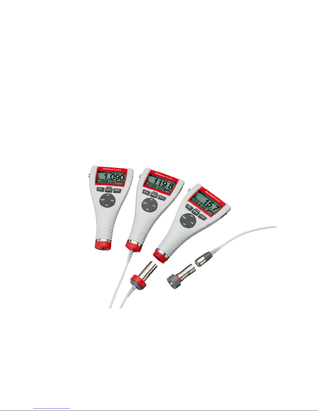
The measuring system comprises a sensor and a display unit. According to model, the gauge
features a built-in sensor, an external sensor or a convertible sensor.
Three basic models are available:
MiniTest 725 with a firmly connected built-in sensor
MiniTest 735 with a firmly connected external sensor
MiniTest 745 with a convertible sensor (can be changed from built-in to external on a lead). All
sensors of the MiniTest 700 series may be connected to this model.
According to sensor type, the gauges are suitable for the following substrate/coating combinations:
The F sensors work on the magnetic-induction principle and are suitable for measuring non-
magnetic coatings such as paint, enamel, rubber, aluminium, chrome, cupper, tin etc. on ferrous
bases and steel (also on alloyed steel or on hardened magnetic steel, but not on austenitic steel or
weak magnetic steel).
The N sensors work on the eddy currents principle and are suitable to measure insulating coatings
such as paint, anodising, ceramics, etc. on all kinds of non-ferrous metals such as aluminium,
cupper, zinc die casting, brass etc. as well as on austenitic steel.
Page 7

© ElektroPhysik MiniTest 725, MiniTest 735, MiniTest 745 7 / 85
The FN sensors work on both, on the magnetic-induction principle as well as on the eddy currents
principle. These sensors can be used for measurement on steel as well as on non-ferrous metal
substrates.
For printing out readings and statistics a portable printer MiniPrint 7000 is available as an option.
All models of the MiniTest 7X5 series are equipped with a USB interface and a Bluetooth interface
to enable data communication to a PC or the MiniPrint 7000 data printer.
For documentation of readings and statistics, all models of the 7X5 series are equipped with a USB
and Bluetooth interface to enable data communication to a PC or to a portable printer MiniPrint
7000 BT (available as an option). For data evaluation, a free of charge software MSoft 7 Basic
Edition is available. In addition, a more extensive software is available, MSoft 7 Professional
Edition (licence required).
Page 8

© ElektroPhysik MiniTest 725, MiniTest 735, MiniTest 745 8 / 85
2. First Steps
This section refers to persons to use the gauge for the first time. This section explains the main
features of the gauge and how to take readings.
2.1 Insert batteries and connect sensor
a) Take gauge and batteries from the case.
b) Loosen the screw of the battery compartment on the back-side of gauge and open the battery
compartment lid (e.g. by using a coin).
c) Insert the batteries supplied with the gauge into the battery compartment. Respect polarities
(as shown below).
d) Close lid and fix screw of battery compartment lid.
e) Above the battery compartment screw, a connection for fixing the hand-strap is located. The
hand-strap comes with the gauge and can be fixed now.
If you have purchased the MiniTest 725 or 735 model, please jump step f).
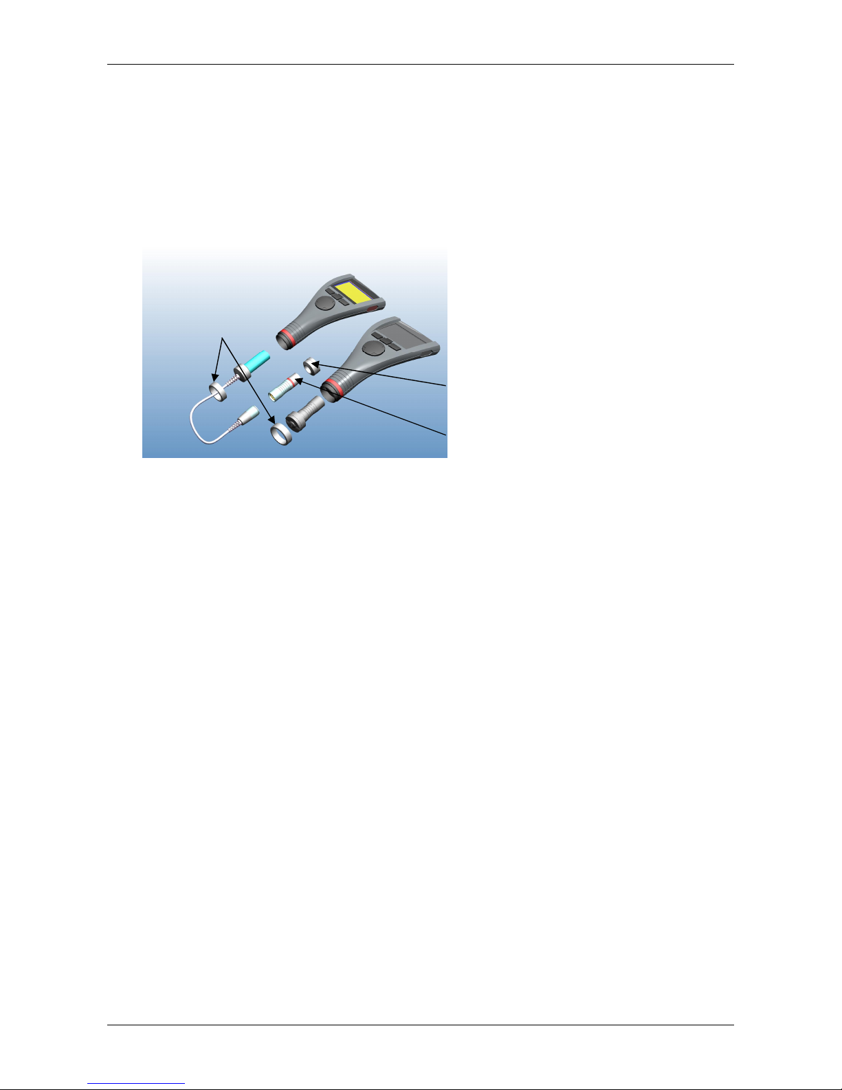
The MiniTest 745 model can be used with both, built-in and external sensor. The gauge comes
with the adapter cable fixed to the gauge for use with the external sensor.
-
For using the MiniTest 745 with external sensor, fix the sensor to the adapter cable. The
MiniTest 745 sensors come with two different types of measuring prisms: one with a small
contact surface for measuring small or curved parts, the second prism with a large contact
surface for large and even surfaces. The large prism serves also for fixing the sensor to the
MiniTest 745.
connection for hand strap
Page 9
© ElektroPhysik MiniTest 725, MiniTest 735, MiniTest 745 9 / 85
-
Use of MiniTest 745 with the external sensor
Connect sensor to adapter cable and screw in tight. The MiniTest 745 sensors come with
two prisms each, one for small curve radii and one for large radii and large surfaces. Select
a suitable prism according to your setting of task and fix it to the sensor.
-
Use of MiniTest 745 with built-in sensor
Turn coupling ring to remove it from the gauge. Remove adapter cable. Fix the large prism
to the sensor. Insert it into the gauge. Use coupling ring to screw in tight. The sensor can be
mounted to the gauge housing at any angle. Adjust the prism as requested for your setting
of task and fix firmly.
2.2 Switch-ON and take readings
Please note: The following steps to perform the initialising sequence need only be performed at
initial use.
1. The gauge must be switched OFF.
2. Press ON/OFF button on the left side of gauge and ESC key simultaneously.
3. Release ON/OFF button first.
The initialising sequence consisting of the following four steps will be launched:
Language
English (factory setting) appears.
Use arrow up/down keys to adjust to the requested language.
Press OK to confirm or ESC to abort and to go back to the previous setting.
If you abort, the factory setting (English) remains.
coupling ring
prism for large curve radii and large surfaces
prism for small curve radii
Page 10
© ElektroPhysik MiniTest 725, MiniTest 735, MiniTest 745 10 / 85
Total Reset Press OK to confirm.
IrDA- Port (cont. active) Press OK to confirm “cont. active”
Power supply (Battery) Press OK to confirm.
For more detailed information on the initialising sequence please refer to section 10.1.
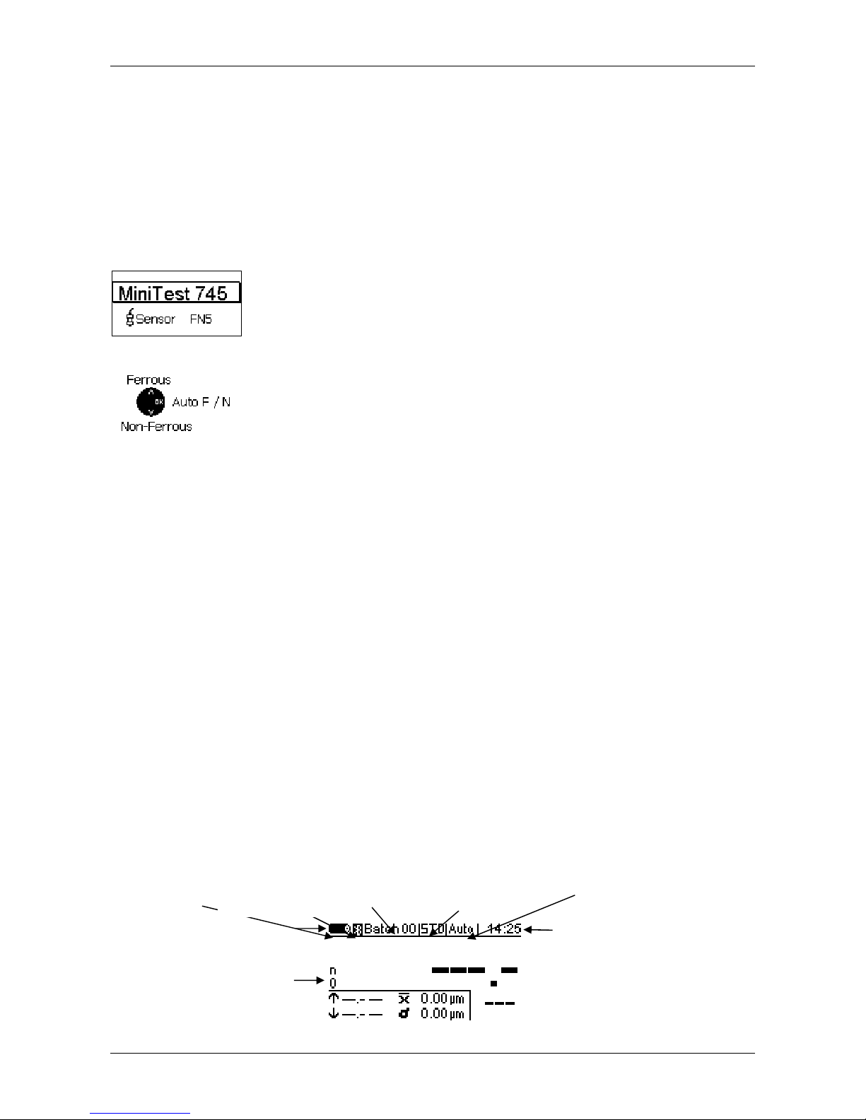
The Start screen appears showing gauge model and sensor type being
connected (see fig. on the left)
With the FN sensors, the measuring method can be selected:
-
Press arrow up key for “Ferrous” (F for magnetic induction method)
-
Press arrow down key for “Non-ferrous” (N = eddy currents method).
-
Press OK to confirm your selection.
If you make no selection at all, the Auto F/N method will be automatically
adjusted after 5 seconds (see fig. on the left).
a) Now the gauge is in the measure mode and ready for measurement. The measure screen
appears (see fig. below). Readings are not yet available.
b) At initial use, “Batch 00” (see section 7.2.2) and the factory pre-setting (“STD”) are active.
For further information on “Calibration”, please refer to section 6. The active batch and the
calibration mode are shown in the status line.
c) The factory pre-setting is recommended for quick and easy measurement and if a medium
measuring accuracy is sufficient. For more details on calibration methods please refer to
section 6.2.
d) To take readings, place the sensor in right angle onto the measuring object. The coating
thickness will be immediately displayed on the screen. Remove sensor and take next
reading.
Status line
Set calibration
method
Active
Batch
Battery
state
Active measuring pro
ce-
dure, here: Auto F/N
Time
Online statistics
Bluetooth active
Page 11
© ElektroPhysik MiniTest 725, MiniTest 735, MiniTest 745 11 / 85
3. Description of the Measuring System
3.1 Gauge
3.1.1 General
Graphics display
128 x 64 dots
LED, green to confirm
acquisition of readings,
red to indicate if limits
have been exceeded
Large backlit graphics display for convenient
reading of readings and statistical values.
The gauge is equipped with a sturdy, scratch-
resistant plastics housing.
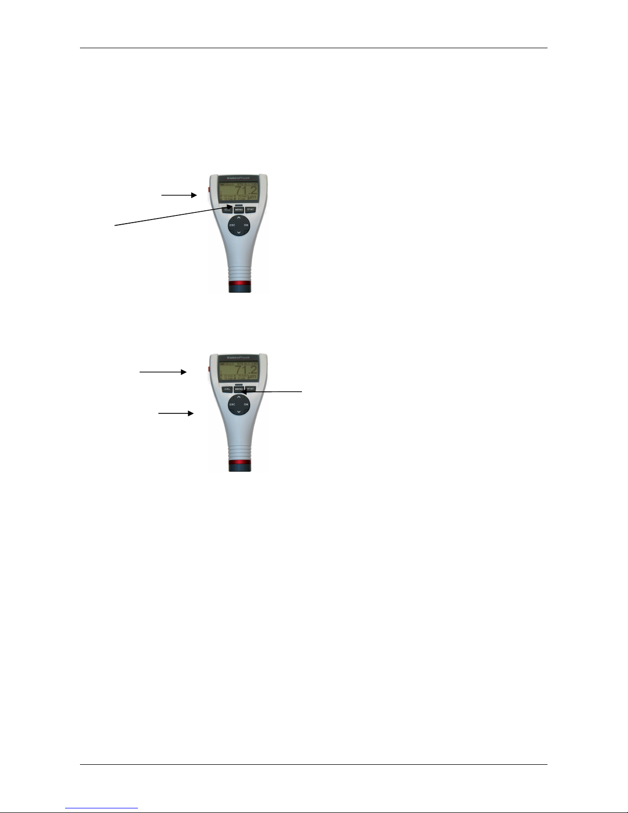
3.1.2 Operating keys
ON / OFF
button
Command and
navigation block
Function keys
Press ON/OFF button to switch the gauge ON or OFF. If you press ON/OFF button and ESC
simultaneously, the initializing procedure will be performed (for more details please refer to section
10.1).
Press Function key CAL to start the calibration procedure.
Press Function key MENU to call the main menu.
Press Function key STAT to call the statistics menu.
The command and navigation key block has the following functions:
-
Press OK to confirm settings or select menu items.
-
Press ESC to abort actions, to quit submenus or to navigate through a batch.
-
Use ARROW up/down keys to navigate through a menu or to change settings.
-
ESC and OK keys assume various functions according to menu being active
Page 12
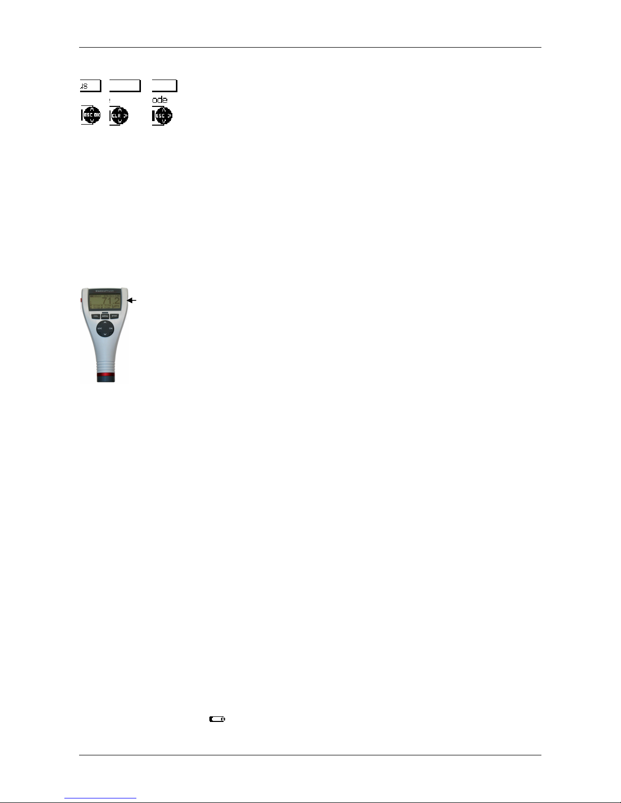
© ElektroPhysik MiniTest 725, MiniTest 735, MiniTest 745 12 / 85
The navigation block symbol indicates the function of keys they
currently assume.
ESC and OK may assume different functions depending on the
menu being active.
So ESC may assume delete function (CLR) and OK may assume “>”
function for “next step”.
3.1.3 Interfaces
Please refer to sections 8.2 and 10.1
3.1.4 Power Supply
3.1.4.1 Batteries and Rechargeable batteries
All models, MiniTest 725, 735 and 745 are powered by a set of two alkaline-manganese cells,
1.5V, AA LR6 size (batteries are included in the standard supply schedule).
As an alternative, all models may also be operated on rechargeable NiMH (type AA-HR6)
rechargeable batteries. Please use only products as recommended by ElektroPhysik (See section
13.3 Accessories).
If you are using the rechargeable batteries, the power source setting must be adjusted accordingly.
(See section 10.1). For charging the rechargeable batteries, an external charger unit (available as
an option) must be used.
For more details on battery use please refer to section 12.1.1.
Note:
Remove batteries or rechargeable batteries from the instrument if not in use for extended
periods.
The battery symbol indicates 5 different battery states.
Infrared port (IrDA)
Page 13

© ElektroPhysik MiniTest 725, MiniTest 735, MiniTest 745 13 / 85
When reaching the lowest battery state, the message “Battery almost empty” appears. In
this state, voltage is insufficient for powering the display backlight. The message “Backlight
failure – replace battery” appears on display.
If batteries are completely discharged, the message “Low battery” appears and the gauge
switches off.
Insert fresh batteries within one minute immediately after removing the used ones. If you
wait for longer than one minute, the message “Check clock settings” will appear (see
section 9.4). However, readings and calibration values will remain in memory.
For field use, replacement batteries should be always at hand.
Erratic readings due to low battery do not occur as the gauge switches off automatically or
does not switch on at all if batteries are too low.
Used or defective batteries or rechargeable batteries may contain hazardous substances
and must be disposed of according to the legal provisions of your country.
Page 14

© ElektroPhysik MiniTest 725, MiniTest 735, MiniTest 745 14 / 85
3.2 Sensors
3.2.1 SIDSP® technology
SIDSP® is world-wide leading technology for coating thickness sensors developed by
ElektroPhysik. With this new technology, ElektroPhysik has set another new benchmark for
innovative coating thickness measurement.
SIDSP® stands for Sensor-Integrated-Digital-Signal-Processing – a technology where the signals
are completely processed into digital form inside the sensor.
Unlike conventional techniques, the SIDSP® sensors create and control the excitation signals for
the sensor head inside the sensor. The return signals are directly digitally converted and
processed at a 32 bits accuracy to give you the complete coating thickness value. For this
technique, highly sophisticated methods of digital signal processing are used. This enables to
achieve a signal quality and precision unmatched so far with analogue signal processing.
SIDSP® sensors display extremely high interference immunity.
Anything that has to do with measuring signals will be handled by SIDSP in direct proximity to the
sensor head. No more interference during data transmission of the measuring signals via asensor
cable– because with SIDSP there is no measuring signal transmission taking place via the senor
cable. The sensor cable only supplies power to the sensor and serves as a communication
interface transmitting the coating thickness values to the display unit - in digital form.
All sensors feature an extremely wear-resistant sensor tip being most suitable also for hard coating
materials.
3.2.2 MiniTest 745 Sensors
For this model, a range of convertible sensors is available to cover the different measuring ranges
and applications. See also section 13.2.4 further details.
Page 15
© ElektroPhysik MiniTest 725, MiniTest 735, MiniTest 745 15 / 85
4. User Interface
4.1 Switch-ON and Start screen
At switch-on, the start screen appears showing gauge version and
sensor version being connected.
Approximately 2 seconds after switch-on, the gauges switches to the measuring mode of the last-
activated batch.
If an FN sensor is connected and if no readings have been taken so far, you can choose the
measuring principle via the keyboard.
Press arrow up key for Ferrous (F) (magnetic induction method).
Press arrow down key for non-ferrous (N) substrates (eddy currents method).
If you press OK, the Auto F/N mode (with automatic substrate identification) will be activated.
If you make no selection at all, the Auto F/N mode will be adjusted automatically after
approximately 5 seconds. In the Auto F/N mode, the gauge automatically identifies the substrate
material to adjust to a suitable measuring principle (magnetic induction or eddy currents).
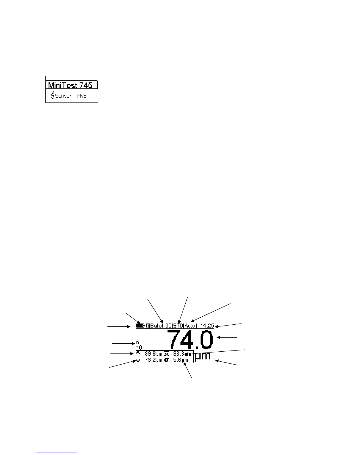
4.2 Measure Mode Screen
Battery indicator
Calibration
method
Active
Status line
Maximum reading
Active measuring
method
Time clock
Number of readings
Standard deviation
Current reading
Average
Miniumum reading
Measuring unit
Page 16
© ElektroPhysik MiniTest 725, MiniTest 735, MiniTest 745 16 / 85
4.2.1 Online Statistics
During acquisition of readings, the measuring screen shows the current statistics of the active
batch in a separate window.
4.2.2 Rotatable Display
In the measuring mode you can rotate the display by 180°.
Press the arrow up/down keys to rotate.
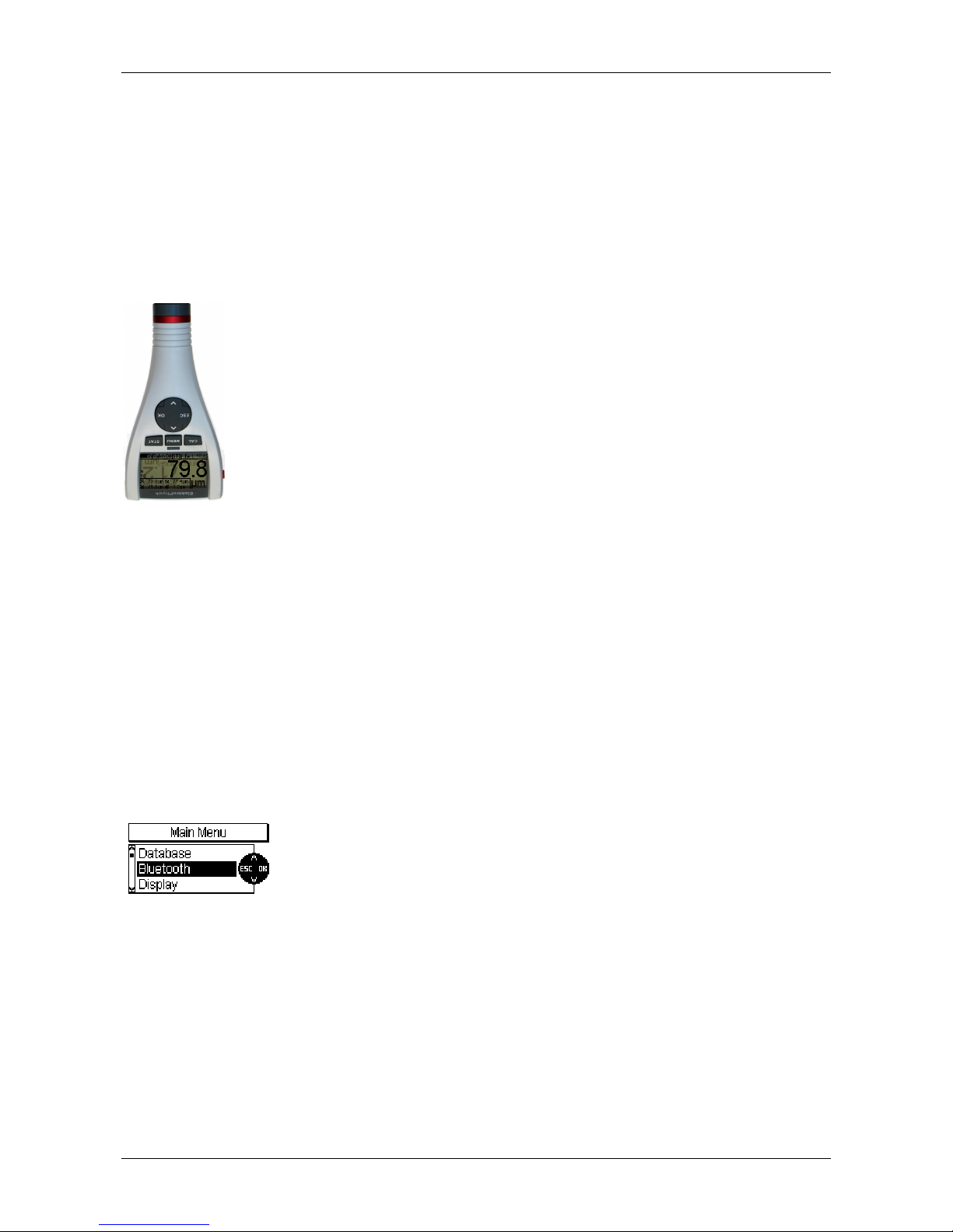
4.4 Menus
The numerous MiniTest features can be accessed via the hierarchic structure of the main menu.
The main menu is subdivided into three submenus: “CAL” (calibration menu), “Menu” (main menu)
and “STAT” (statistics menu). These menus can be accessed via the CAL, Menu and STAT keys.
Press the Function key Menu to access the main menu.
Use arrow keys to select an item from the menu, e g. „SIDSP“.
Press OK to confirm your selection.
A submenu will open or a function will be called. (e. g. “Print”).
To go back to the previous menu level press ESC.
The parameter and data grouped as grouped under the various menus and submenus may be
divided into three categories:
-
predefined parameters that may be selected from a list
-
numerical parameters that may be adjusted within predefined limits
-
fixed parameters that may only be viewed but not changed
Page 17

© ElektroPhysik MiniTest 725, MiniTest 735, MiniTest 745 17 / 85
4.4.1 Setting predefined parameters
Use arrow up / down keys to scroll through the list of options of the
main menu.
Press OK to confirm you selection, e.g. “Language”.
Press OK to confirm.
Use arrow up / down keys to select a language.
Press OK to confirm. Your selection has been enabled.
To abort, press ESC before confirming your selection.
You will go back to the language selection level.
4.4.2 Setting Numerical Parameters
Numerical parameters can be changed within their predefined ranges.
Use arrow up / down key to change as requested.
If there is no predefined value available (display will show „---.--"), press
arrow up key to show the maximum value and arrow down key to show
the minimum value.
A brief pressing of arrow up / down keys will change the value to the
next increment. Pressing arrow keys continuously will increase the
setting speed accordingly (as with the repeat functions of PCs).
Press OK to confirm your setting or ESC to abort and to return to the
previous menu.
Page 18

© ElektroPhysik MiniTest 725, MiniTest 735, MiniTest 745 18 / 85
5. Measuring
5.1 Important Notes on Coating Thickness Measurement
Make sure the operator has been properly instructed regarding the use of coating thickness
gauges and has basic knowledge of the specific requirements for measurement of the application.
The operator should have basic knowledge of the following:
Appropriate selection of a measuring device suitable for his application
Fundamentals on the electro-magnetic measuring principle
Influences trough magnetic fields and the surrounding fields
Influence through the surface properties of the object to be tested (roughness, shape and
build-ups on the surface)
Statistical evaluation of measuring series
5.1.1 Interpretation of readings
The information obtained from the coating thickness measurement only refers to those parts of the
test object that have been covered by the sensor. For that reason, conclusions may not be drawn
on parts of the measuring object that have not been covered by the sensor during measurement. In
general, such conclusions are only admissible if comprehensive experience and approved
methods of statistical data acquisition are available.
5.2 Necessary Settings
Before taking readings, it is necessary to make a few settings in the “Data base” menu and the
“Batch” submenu.
5.2.1 Batch
With the MiniTest 700 series, readings are basically grouped into batches. A reading that has been
taken will be listed and stored into the currently active batch. After a switch-off, the gauge will recall
the last used batch so that you can conveniently continue to take readings in the last batch.
You can choose from the following batch actions:
-
Continue to take readings in the active batch
-
Create a new batch in the data base (see section 7.2.2)
-
Select an existing batch form the data base (see section 7.2.3)
Page 19

© ElektroPhysik MiniTest 725, MiniTest 735, MiniTest 745 19 / 85
5.3 Preparing Measurement
5.3.1 Calibration
According to your setting of task, you may use different calibration methods. Measuring accuracy
depends on the selected calibration method. Please refer to section 6.2 for more details on this
issue.
The following calibration methods are available:
-
Factory pre-setting
-
Manual calibration
o Zero calibration
o Two-point calibration
o Multi-point calibration
-
Pre-set calibrations „SSPC-PA2“, „Australian“, „Swedish“, „ISO“ and „Rough”
5.4 Taking Readings
5.4.1 Taking readings without using the sensor stand
All sensor systems are spring-mounted to ensure a safe contact pressure on the measuring object
without tilting. The V-groove of the sensor ensures correct positioning of the sensor on cylindrical
objects.
To take readings, place the external sensor of the MiniTest 735 or 745 model and/or, with the built-
in sensor, the complete gauge (MiniTest 725 or 745) onto the object to be measured. As soon as
the sensor has been placed onto the object, a reading will be displayed.
In the “Single readings mode”, the reading will be stored into the active batch. Lift the sensor briefly
and take the next reading.
In the „Scan mode“, readings are displayed continuously as long as the sensor is being placed on
the object. To store the single reading being displayed into the active batch, press OK key.
Please avoid scratching the sensor over the object to be measured in order to prevent wear-and-
tear of the sensor pole.
Page 20
© ElektroPhysik MiniTest 725, MiniTest 735, MiniTest 745 20 / 85
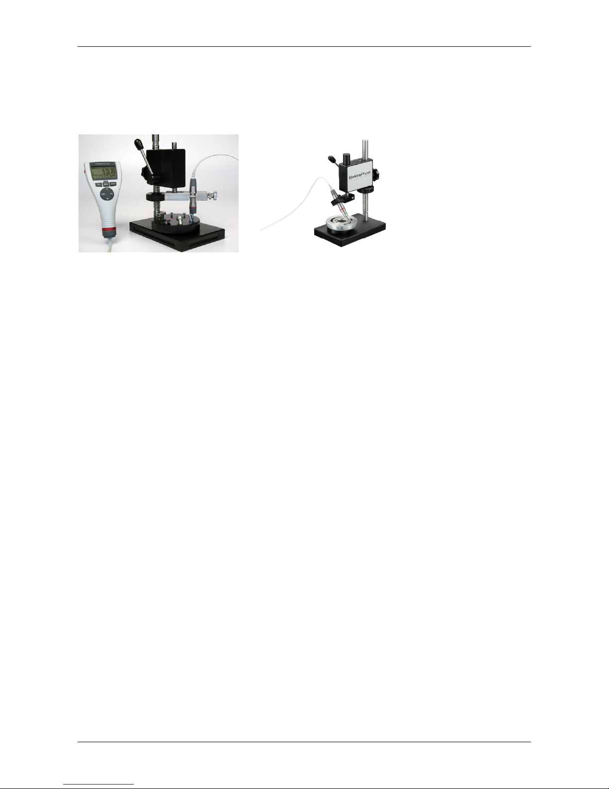
5.4.2 High-precision stand
For taking readings on small objects and small geometries, it is recommended to use the external
sensor in connection with the high-precision stand.
Using the standard sensor Using the miniature sensor SIDSP© F05-M 45°
5.4.3 Duplex coating systems
To add additional corrosion protection to a product or for design reasons, it is common practice to
apply a zinc coating to a steel product before painting. For measurement of zinced steel with
additional surface finish, please use the dual sensors FN1.5 or FN5 sensors. With these sensors,
you can determine the thickness of the zinc coating as follows:
1. Set the gauge to ferrous substrates and take reading. The total thickness of zinc plus
surface finish will measured (thickness # 1)
2. Set the gauge to non-ferrous substrates. The zinc coating will be considered as non-ferrous
substrate and the thickness of paint will be measured (thickness # 2)
3. Now you can evaluate the thickness of zinc coating by calculating the difference between
the thickness #1 and thickness #2.
Please note that for measurement of duplex coating systems, a minimum zinc thickness of 50µm is
prerequisite. For checking whether your zinc coating thickness is sufficient, please take zero value
in the non-ferrous setting. Starting from a 50µm zinc thickness, the zero value is sufficiently good
so that you can measure your duplex coating as described above.
5.5 Errors during measurement
After the sensor has been calibrated, you can proceed on taking readings in the measuring mode.
Readings will be correct as long as the sensor specifications will be observed. Please refer also to
section 6.1 Calibration „General remarks“and Section 13 „Technical specifications“.
Page 21

© ElektroPhysik MiniTest 725, MiniTest 735, MiniTest 745 21 / 85
5.6 Measurement on hot surfaces (HT mode) with high-temperature sensors up to 350°C
(HT-mode)
The measuring system MiniTest 700 (gauge with sensor) is designed for a maximum operating
temperature of 60°C. Whilst the current operating temperature of the gauge depends on the
ambient temperature of the air, the current operating temperature of the sensor is also influenced
by the surface temperature of the object to be measured. This is due to the heat transfer taking
place when the sensors comes into contact with the object to be measured.
Measurements on objects with surface temperatures higher than the specified sensor operating
temperature are permissible with the special high-temperature sensors (such as item 80-173-5600
“F5 HT – 350°C”) under the following conditions:
1. When taking readings, a measuring signal will sound approx. 1 second after placing the
sensor onto the object to be measured in order to confirm acquisition of the reading. Make
sure to lift the sensor immediately after the bleep sounds. This is to keep the heat transfer
from the object to the sensor as low as possible. Do not keep the senor in contact with the
measuring object for longer than one second.
2. Note that between two subsequent measurements on hot surfaces, a recovery time is
required to cool down the sensor. Please refer to the table below for the temperature
depending recovery times. If the below recovery times are respected, a virtually unlimited
number of subsequent measurements can be taken.
3. During a measurement pause, make sure not to place the sensor on hot surfaces to
prevent heating up. Keep the sensor away from hot measuring objects to prevent heating
up through heat radiation.
Sensor recovery times in HT mode
Temperature
in °C
100°C 150°C 200°C 250°C 300°C 350°C
Recovery
time in
seconds
1 sec 2.5 sec 6 sec 12 sec 20 sec 30 sec
Page 22

© ElektroPhysik MiniTest 725, MiniTest 735, MiniTest 745 22 / 85
6. Calibration
6.1 General remarks
The MiniTest 700 series offers a number of calibration methods to meet the individual
requirements of various applications, procedures and industrial standards. If a batch is being
created you can select a suitable calibration method for this batch. The calibration can be carried
out immediately after you have created a batch or at a later time in the measuring mode. To call up
the calibration function in measure mode, press function key CAL. The calibration method can be
changed as long as no readings are stored in the currently active batch.
A calibration is made in the currently active batch and is directly related to this batch.
To ensure an optimum calibration, the following points should be observed:
Correct calibration is vital for accurate measurement. For calibration, a sample similar to
the later object to be measured should be used, i.e. both, calibration sample and the object
to be measured should be of the same shape and geometry. As a rule, you can say that the
more similar the calibration sample and the later object to be measured are, the more
accurate calibration and thus accuracy of readings will be.
Make sure the calibration sample and the later object to be measured have same
characteristics such as:
- identical curvature radius of surface
- identical substrate materials (such as magnetic permeability, electrical conductivity; in the
ideal case, they should be made of the same material)
- identical substrate thickness
- identical size of measuring area
Before starting calibration, make sure the calibration spot, the sensor tip and the calibration
standard are clean. If necessary, remove any built-ups such as grease, metal chips, etc.
Any impurities might affect calibration and lead to erratic calibration.
Make sure the calibration position and the measuring position are always the same, this
applies especially for measurement on small parts and measurements at edges and
corners.
Keep away from strong magnetic fields during the calibration procedure.
For maximum accuracy of calibration and later measurements, choose the thickness of
calibration standard within the same thickness range as the later measuring sample.
Page 23

© ElektroPhysik MiniTest 725, MiniTest 735, MiniTest 745 23 / 85
For measuring thick non-ferrous metal coatings on steel or ferrous substrates according to
the magnetic induction method (with F1.5, FN1.5, F5, FN5 or F15 sensors), a multi-point
calibration must be carried out. The thickness standards must be of the same metal as the
later object to be measured.
If using calibration foils, make sure they are placed in plane position on the substrate
material. Any air gap below the foils must be avoided as this would lead to erratic readings.
If the foils are curved, make sure to place on them on the substrate as shown below.
The precision thickness standards must be handled with care. Any wear-and tear of the thickness
standard will be reflected as erratic calibration value. Do not fold calibration foils. Any buckling will
cause air gaps below the foil and result in erratic readings. Keep thickness standard clean, free
from grease, oil, dust or other build-ups. Build-ups on the foils will be considered as thickness and
will lead to a measuring error of the same value as thickness of build-up. To give you a rough idea:
a build-up from a finger-print will be enough to add an additional thickness of some microns.
Please note:
If the gauge switches off during the calibration procedure due to low battery, the calibration
procedure must be repeated after batteries inserting fresh batteries.
6.2 Calibration methods
According to your setting of task, you may use different calibration methods. Measuring accuracy
depends on the selected calibration method. For more details please refer to section 13.2 Sensor
Specifications.
6.2.1 Factory pre-setting
The status line shows “Factory“ (“STD”)
The factory pre-setting is used for quick and easy measurement with a medium accuracy (for more
details please refer to section 13.2 Sensor Specifications). This calibration mode setting will be
valid as long as you do not choose and/or activate another calibration mode.
Page 24

© ElektroPhysik MiniTest 725, MiniTest 735, MiniTest 745 24 / 85
6.2.2 Manual calibration method
6.2.2.1 Zero calibration
”Z” is shown in the status line
calibration point: zero point (directly on the substrate material)
Calibration is to be made on an uncoated calibration sample of the same geometry and material as
the later measuring object. Only one calibration point is to be taken directly on the substrate to give
you the zero point.
Zero calibration is for quick calibration if a medium accuracy is sufficient.
6.2.2.2 Two-point calibration
”Z 1” is shown in the status line
Calibration points: zero point (directly on the substrate material) and on the precision standard.
Calibration is to be made on an uncoated calibration sample of the same geometry and material as
the later measuring object. Two calibration points are to be taken: one directly on the substrate to
give you the zero point, the other one on a precision standard which is put on the substrate.
Compared to the zero calibration, this calibration method implies a higher accuracy. Accuracy will
increase if the thickness of the precision standard is close to the thickness of the later object to be
measured.
6.2.2.3 Multi-point calibration
“Z 12” is shown in the status line.
Calibration points: zero point (directly on the substrate material) and on two precision standards.
Calibration is to be made on an uncoated calibration sample of the same geometry and material as
the later measuring object. Three calibration points are to be taken: one directly on the substrate to
give you the zero point, and two further ones on two precision standards to be put on the substrate.
It is recommended to choose a precision standard to cover the lower half of expected thickness
range, the other one should be in the higher half of expected thickness range.
This calibration method should be used if readings are to be taken over an extended thickness
range and if a high accuracy is required.
Page 25

© ElektroPhysik MiniTest 725, MiniTest 735, MiniTest 745 25 / 85
6.2.2.4 Two-point calibration without zero calibration
”12” is shown in the status line
calibration points: two precision standards (no zero point)
Calibration is to be made on an uncoated calibration sample of the same geometry and material as
the later measuring object. Two calibration points are to be taken on two precision standards which
are to be put on the substrate. The first precision standard should be thinner than the thickness to
be expected, the other one should be thicker than the thickness to be expected. There is no zero
point to be taken directly on the uncoated sample.
This specific calibration method should be used when taking readings on rough surfaces. Taking
zero point on rough surfaces would imply strong deviations due to the uneven surface. That’s why
zero point is omitted in this calibration method as this would lead to erratic calibration and thus
affect accuracy.
6.2.3 Defined, menu-guided calibration methods
6.2.3.1 General remarks
For all defined and menu-guided calibration methods the following applies:
The selection of a defined calibration method is made during the creation of a batch. After you
have completed the set-up of a batch, you may proceed on the menu-guided calibration. The
factory calibration will be valid until you have completed the calibration procedure. A running
calibration procedure is indicated by CAL flashing in the status line.
6.2.3.2 Calibration according to ISO (EN ISO 19840)
“ISO” is shown in the status line.
Calibration points: zero point (directly on the substrate material) and on two precision standards.
This standard does not apply if the target thickness is less than 40 microns.
Calibration is made on the uncoated calibration sample of the same geometry and substrate
material as the later object to be measured. Three calibration points are to be taken: zero point
(directly on the substrate) and two further one on two precision standards which are to be put on
the substrate. The first precision standard should be thinner than the thickness to be expected, the
other one should be thicker than the thickness to be expected.
Page 26

© ElektroPhysik MiniTest 725, MiniTest 735, MiniTest 745 26 / 85
To compensate for roughness, a correction value related to the actual roughness of sample must
be used according to the table below. As an alternative, a specific correction value can be
determined according to Method A (see section 6.3.2) and set accordingly.
If the roughness value is not known and no uncoated sample is available, the correction value “25
microns” should be used.
It is recommended to take sufficient readings according to the size of measuring area. A minimum
number of 5 readings should be taken.
The block statistics defines a number of 5 readings per block. If required, e. g. for larger surfaces,
you can increase the number of readings per block accordingly.
Roughness profile according to
ISO 8503-1
Correction value
(roughness) microns
fine 10
medium 25
coarse 40
6.2.3.3 Calibration method „rough“
“RGH” is shown in the status line.
Calibration points: on two precision standards (no zero point)
This calibration method is used for rough surfaces such as on blasted samples.
Two calibration points are to be taken on two precision standards which are to be put on the
substrate. The first precision standard should be thinner than the thickness to be expected, the
other one should be thicker than the thickness to be expected. There is no zero point to be taken
directly on the uncoated sample.
To achieve a maximum adaptation to the surface roughness of sample, you may use several
precision standards (50 µm max. thickness each) to lay them on top of each other. Thin precision
standards are more flexible than the thick ones and thus better adapt to uneven surfaces.
Take at least 5 to 10 readings to calculate the average thickness.
6.2.3.4 Calibration method “Swedish” (SS 18 41 60)
“SWD” is shown in the status line.
Calibration points: on two precision standards (no zero point)
Two calibration points are to be taken on two precision standards which are to be put on the
substrate. The first precision standard should be thinner than the thickness to be expected, the
Page 27

© ElektroPhysik MiniTest 725, MiniTest 735, MiniTest 745 27 / 85
other one should be thicker than the thickness to be expected. There is no zero point to be taken
directly on the uncoated sample.
The block statistics defines a number of 5 readings per block.
6.2.3.5 Calibration method “Australian”
“AUS” is shown in the status line.
Calibration points: zero point (directly on the substrate) and on one precision standard.
Two calibration points are to be taken: one directly on the substrate (zero point) and another one
on a precision standard. The precision standard should be in the thickness range of the later object
to be measured.
The block statistics is defined for a minimum of 3 readings per block.
If coating thickness is less than threefold the value of roughness profile height, the
roughness of the substrate material must be taken into consideration.
If the uncoated rough substrate can be accessed, a two-point calibration as described
under section 6.4.3.3 should be made on the uncoated, smooth (non-blasted) and clean
calibration sample of the same geometry and material as the later measuring object.
After this, at least 10 readings should be taken on the rough (non-blasted) and uncoated
measuring object. Enter the roughness mean value as roughness value in the setting “1/3
profile height” of the current batch. The roughness value you have entered will be
subtracted automatically from the thickness reading to give you the coating thickness over
the peaks.
If there is no access to the uncoated rough substrate, the parameter “1/3 profile height”
must be set to 1/3 of the expected profile height. Example: 60 microns => Value to be set
for “1/3 profile height” 20 microns.
6.2.3.6 Calibration according to SSPC-PA2
“SSPC” is shown in the status line.
This method applies for rough substrates such as blasted or ground samples.
Case 1: The sample to be measured is completely coated (no access to the blank substrate)
-
Calibration points: zero point (directly on the substrate of a calibration object) and two
further ones on two precision standards.
Calibration is made on the uncoated, smooth sample. The sample should have the same
Page 28

© ElektroPhysik MiniTest 725, MiniTest 735, MiniTest 745 28 / 85
geometry and substrate material as the later object to be measured (please refer to section
6.2.2.3 Multi-point calibration).
The block statistics defines a number of 3 readings per block.
To compensate for roughness, a correction value according to the table below must be
used. As an alternative, a specific correction value can be determined and set accordingly.
If the roughness value is not known and no uncoated sample is available, a correction value
“25 microns” should be used.
-
A suitable number of readings should be taken according to the size of area to be
measured.
The block statistics defines a number of 3 readings per block.
Roughness profile according to
ISO 8503-1
Correction value
(roughness) microns
fine 10
medium 25
coarse 40
Case 2: The sample is not coated completely (the substrate can be accessed)
-
A calibration according to section 6.3.4 \ Method C or according to the predefined
calibration method “Rough” is to be carried out. During the creation of a batch select
“Manual” our “Rough”. Set the block statistics to 3 reading per block.
6.3 Blasted and rough surfaces
6.3.1 General remarks
To remove rust in order to ensure a good adhesion of the paint, surfaces are commonly blasted in
pre-treatment. As a result, the base material gets rough. Roughness influences the measuring
results, i.e. readings will be higher than the actual thickness.
The following section describes some steps how to remove the influence of roughness in coating
thickness measurement.
For calibration and for determining the average, it is generally recommended to take at least a set
of 10 readings.
If you proceed on thickness measurement according to the steps below, the average thickness
over the peaks will be displayed. Note that the statistics program is of great benefit in this
procedure.
Page 29

© ElektroPhysik MiniTest 725, MiniTest 735, MiniTest 745 29 / 85
6.3.2 Method A (Roughness Rz > 20µm)
When creating the batch, adjust calibration method to “Manual“.
Calibration points: zero point and on one precision standard.
-
Carry out a two point-calibration according to section 6.4.3.2. Use a smooth (non
blasted) and clean calibration sample with the same geometry and the same
substrate as the later measuring sample.
-
Take approx. 10 readings on the uncoated, rough (blasted) sample to produce the
mean value. Enter this value as roughness value in the “Roughness” setting of
batch.
The roughness value you have entered will be automatically subtracted from the thickness value to
give you the thickness value over the peaks. Take a set of at least 10 readings on the coated and
rough (blasted) sample.
6.3.3 Method B (Roughness Rz < 20µm)
When creating the batch, adjust calibration method to „Manual“.
Calibration points: zero point and on a precision standard.
-
Carry out a two point-calibration according to section 6.4 3.3. Use an uncoated, rough
(blasted) and clean calibration sample with the same geometry and the same substrate
material as the later measuring sample.
-
Take at least 10 readings on the uncoated calibration sample followed by 10 readings on
the precision standard. To ensure an optimum adaptation to the surface roughness you
may use several precision standards (of max. 50 µm thickness each) and lay them on top
of each other. The thin precision standards are more flexible than the thick ones to adapt
better to the surface roughness. The calibration value should roughly correspond to the
coating thickness to be expected.
For thickness measurement, the average thickness is calculated from a set of 5 to 10 individual
readings.
6.3.4 Method C
-
Calibration using two different precision standards. Also this method provides reliable
results. It is the two-point calibration without zero point according to section 6.4.
Page 30

© ElektroPhysik MiniTest 725, MiniTest 735, MiniTest 745 30 / 85
-
To achieve a maximum adaptation to the surface roughness of sample, you may use
several precision standards (50 µm max. thickness each) to lay them on top of each other.
Thin precision standards are more flexible than the thick ones and thus better adapt to
uneven surfaces.
-
Take at least 5 to 10 readings to calculate the average thickness.
Please note: With coatings thicker than 300 µm, the influence of roughness can be neglected.
That’s why for this coatings, the above calibration methods can be omitted here.
6.4 How to calibrate
6.4.1 General remarks
For all calibration methods applies:
-
The required calibration method is to be selected while you create a batch. Please refer to
section 7.2.2.
For all calibration methods except for the factory calibration applies:
-
For optimum calibration accuracy it is recommended to take several readings for each
calibration point. The gauge automatically calculates the average in order to reduce the
variations and erratic readings to a minimum.
-
Calibration may be effected in both, in the “single reading” mode or in the “scan” mode.
-
Once readings are stored in a batch, you cannot change the calibration method that has
been used for taking readings in this batch.
However you can recalibrate in the adjusted calibration method.
For a new zero calibration, you have to run through the complete list of
calibration points.
For the other calibration points, they may be recalibrated individually by
means of the precision standards.
6.4.2 Factory calibration (STD)
If the factory calibration is active, you may immediately proceed on
measurement after the batch creation has been completed.
Page 31

© ElektroPhysik MiniTest 725, MiniTest 735, MiniTest 745 31 / 85
6.4.3 Manual calibration
In measure mode, press function key CAL to call the calibration mode.
6.4.3.1 Calibrating FN sensors
If a the measuring method “Auto-F/N” has been defined for a batch you
may calibrate for both, the ferrous and the non-ferrous base. In this
case, the calibration procedure will be performed twice. You will
automatically be asked to select the first base for which you wish to
calibrate. Use arrow up and down keys to make your selection and
press OK to confirm. After the calibration for your selected base has
been completed, you will be asked to choose the next one. Use arrow
up/down keys to make your selection and press OK to confirm. Perform
calibration accordingly. After this you will be asked again to select a
base. If calibration for both bases has been completed, you can quit
calibration by pressing “ESC”. You will go back to the measure mode.
6.4.3.2 Zero point calibration
Start calibration and put the sensor on the blank/uncoated calibration
sample. Wait for the signal to sound and lift sensor. Please observe the
instructions in section 6.1 General.
Repeat this procedure several times (approx. 3 to 10 times) on the
same measuring spot. The average will be shown. Evaluation of
average is to increase accuracy of calibration. Accuracy will increase
with an increasing number of readings. Press OK to confirm zero
calibration. Press OK once again to complete the calibration procedure.
You will be asked to calibrate on the first precision standard. Press OK
to jump this step.
A list will appear to show you the points that have been calibrated.
Press OK to go back to the measure mode. In the Auto F/N calibration
you will go back to the base selection.
Page 32

© ElektroPhysik MiniTest 725, MiniTest 735, MiniTest 745 32 / 85
6.4.3.3 Two-point calibration
Start calibration and put the sensor on the blank/uncoated calibration
sample. Wait for the signal to sound and lift sensor. Please observe the
instructions in section 6.1 General.
Repeat this procedure several times (approx. 3 to 10 times) on the
same measuring spot. The average will be shown. Evaluation of
average is to increase accuracy of calibration. Accuracy will increase
with an increasing number of readings. Press OK to confirm zero
calibration. Press OK once again to complete the calibration procedure.
Put a precision standard on the uncoated calibration sample. Place the
sensor on top of it, wait for the signal to sound and lift sensor. Repeat
this procedure several times (approx. 3 to 10 times) on the same
measuring spot. The average will be shown.
If the set point (Cal) as displayed is not identical with the thickness of
your precision standard, use arrow up and down keys to adjust
accordingly.
Press OK to store the calibration point. Press OK once again to
complete the calibration procedure.
You will be asked to calibrate on the second precision standard. Press
OK to jump this step.
A list will appear to show you the points that have been calibrated.
Press OK to go back to the measure mode. In the Auto F/N calibration
you will go back to the base selection routine.
Page 33

© ElektroPhysik MiniTest 725, MiniTest 735, MiniTest 745 33 / 85
6.4.3.4 Multi-point calibration
Start calibration and put the sensor on the blank or uncoated calibration
sample. Wait for the signal to sound and lift sensor.
Repeat this procedure several times (approx. 3 to 10 times) on the
same measuring spot. The average will be shown. Evaluation of
average is to increase accuracy of calibration. Accuracy will increase
with an increasing number of readings. Press OK to confirm the
calibration point. Press OK once again to complete the calibration
procedure.
Put the first precision standard on the uncoated calibration sample.
Place the sensor on top of it, wait for the signal to sound and lift sensor.
Repeat this procedure several times (approx. 3 to 10 times) on the
same measuring spot. The average will be shown.
If the shown set point (Cal) as displayed is not identical with the
thickness of your precision standard, use arrow up and down keys to
adjust accordingly.
Press OK to confirm the calibration point.
Put the second precision standard on the uncoated calibration sample.
Place the sensor on top of it, wait for the signal to sound and lift sensor.
Repeat this procedure several times (approx. 3 to 10 times) on the
same measuring spot. The average will be shown.
If the shown set point (Cal) as displayed is not identical with the
thickness of your precision standard, use arrow up and down keys to
adjust accordingly.
Press OK to confirm the calibration point.
Page 34

© ElektroPhysik MiniTest 725, MiniTest 735, MiniTest 745 34 / 85
A list will appear to show you the points that have been calibrated.
Press OK to go back to the measure mode. In the Auto F/N calibration
you will go back to the base selection routine.
6.4.3.5 Two-point calibration without zero point
Start calibration. Press OK to jump zero point calibration.
Put the first precision standard on the uncoated calibration sample.
Place the sensor on top of it, wait for the signal to sound and lift sensor.
Repeat this procedure several times (approx. 3 to 10 times) on the
same measuring spot. The average will be shown. Evaluation of
average is to increase accuracy of calibration. Accuracy will increase
with an increasing number of readings.
If the shown set point (Cal) as displayed is not identical with the
thickness of your precision standard, use arrow up and down keys to
adjust accordingly.
Press OK to confirm the calibration point.
Put the second precision standard on the uncoated calibration sample.
Place the sensor on top of it, wait for the signal to sound and lift sensor.
Repeat this procedure several times (approx. 3 to 10 times) on the
same measuring spot. The average will be shown.
If the shown set point (Cal) as displayed is not identical with the
thickness of your precision standard, use arrow up and down keys to
adjust accordingly.
Press OK to confirm the calibration point.
Page 35

© ElektroPhysik MiniTest 725, MiniTest 735, MiniTest 745 35 / 85
A list will appear to show you the points that have been calibrated.
Press OK to go back to the measure mode. In the Auto F/N calibration
you will go back to the base selection routine.
6.5 How to recalibrate
If measuring conditions have changed, it may become necessary to recalibrate without changing
the calibration method. This can be done at any time, even if readings are stored in the relevant
batch (Please note that it is NOT possible to change the calibration mode of an existing batch with
stored readings).
If you have put the sensor on the uncoated sample the message as
shown on the left will appear. If during recalibration you refresh zero,
you have to repeat all subsequent calibration points.
Press OK to confirm and go through the calibration procedure as usual.
If you do not refresh the zero point and jump this point, the alert
message as shown on the left will be omitted. Only the recalibrated
points will be replaced.
6.6 Interrupt or abort a calibration procedure
Press ESC to interrupt or abort a calibration procedure. According to the situation, the following
reactions may occur:
Situation 1:
If a calibration value has not yet been taken:
If you press ESC you will go back to measure mode. The previous
calibration will remain active.
Page 36

© ElektroPhysik MiniTest 725, MiniTest 735, MiniTest 745 36 / 85
Situation 2:
If you have taken at least one calibration value for any calibration point
but the calibration procedure for this point has not been completed, i.e.
you have not pressed OK to confirm:
If you press ESC you can select from the following list:
Continue: You will continue calibration, all calibration points and values
you have taken so far will remain valid.
Repeat: The calibration values you have taken for the previous
calibration point will be deleted. You can continue the calibration
procedure for the previous calibration point.
Cancel: All calibration points and values will be deleted. The previous
calibration will become valid.
Use arrow up or down keys to select your preference from the list.
Press OK to confirm.
Situation 3:
If you have completed at least one calibration point and you have
confirmed by pressing OK or if you have jumped one calibration point
but the calibration procedure has not yet been completed, i.e. if you
may take some more calibration points:
If you press ESC, you will be asked whether to c
ancel calibration or not.
Use arrow up or down keys to make your selection. Press OK to
confirm. If you choose “No”, the calibration procedure will be continued.
If you choose “Yes”, the calibration procedure will be completed at this
step and all calibration points you have taken so far will be stored. This
will be the same effect as pressing OK once again after a calibration
point has been taken.
6.7 Delete a calibration point
After a calibration procedure has been completed, you may delete
individual calibration points or delete the whole calibration.
Use arrow up and down keys to select the calibration point to be
Page 37

© ElektroPhysik MiniTest 725, MiniTest 735, MiniTest 745 37 / 85
deleted. Press ESC to delete. For safety reasons, the checkback as
shown on the left will appear. If you select YES, the calibration value
you have selected will be deleted.
After deletion, the remaining calibration points will be renumerated. If,
e.g. in a multi-point calibration, you delete point 1, the former point 2 will
change to point 1.
If you delete the zero calibration point, the complete calibration will be
deleted.
Note: Readings stored in a batch will remain valid even if you delete all
or only some of the calibration points.
Page 38

© ElektroPhysik MiniTest 725, MiniTest 735, MiniTest 745 38 / 85
6.8 Calibration – Quick reference
Measure mode
Last calibration
active
ESC
No
Non-Ferrous
Place sensor
n x on blank
metal
ESC
OK
Calibration
already
exists?
sensor FN?
Ja
No sensor = N
CAL
No sensor = F
Ferrous
OK
Place sensor
Evaluate reading
Ja
Place sensor
n x on 1st standard
Calibration for
Ferr. or nonferr.
ESC
OK
Calibration
available?
Ja
after 10 sec.
or press OK
sensor FN?
No
OK
OK
SET
ESC
OK
ESC
ESC
SET
Nein
yes
OK
CLR
CLR
ESC
No
Ja
Selected value
will be deleted
Calibration aborted
Factory calibration
active
after 2 sec.
or press OK
meas. mode
OK
ESC
Abort
continue
repeat
Abbruch
continue
repeat
Abbruch
continue
repeat
Values are
reset
Werte werden
zurückgesetzt
Values
are reset
Place sensor n x
on 2nd standard
Page 39

© ElektroPhysik MiniTest 725, MiniTest 735, MiniTest 745 39 / 85
7. Data Management
7.1 Batches
7.1.1 General remarks
With all models of the MiniTest 700 series, readings, calibrations, statistics and parameters are
stored as a set of data into a batch, i.e. apart from the readings, a batch includes its individual
calibration, setting parameters and statistics. If you open an existing batch, the calibration and
parameters stored in this batch will become active.
Go to the main menu and select “Data base” to view all batches. The batch names (BATCHxx) are
predefined.
-
The MiniTest 725 model features 10 batches.
-
The MiniTest 735 model features 10 batches.
-
The MiniTest 745 model features 100 batches.
If you are in measure mode, the currently active batch is shown in the status line (upper display
line). It is referred to as „BATCHxx“. xx = is the current number of batch.
7.1.2 Memory Size
The memory of the MiniTest 725 and 735 models are designed to store a total of 10,000 readings.
The MiniTest 745 model can store up to 100,000 readings.
With all models, the memory can be divided into batches according to customer requirements. So
you can use for instance the complete memory for one single batch only. The space of a batch will
be assigned automatically according to your requirements, i.e. you do not have to predefine the
size of a batch.
7.1.3 Parameters
All measuring series include the following parameters: “Calibration method”, “Substrate”, “Measure
mode”, “Roughness” (1/3 profile depth with “Australian” calibration method”), “Offset”, “Block size”,
“Upper limit” and “Lower limit”.
It may occur that not all parameters are available, this depends on the calibration method you have
selected (see table of parameters).
Page 40

© ElektroPhysik MiniTest 725, MiniTest 735, MiniTest 745 40 / 85
If you call an existing batch, the parameters and calibration related to this batch will be activated.
As a rule, each batch is related to the sensor that has been used while creating this batch. This is
of no importance to the MiniTest 725 and 735 as these models feature a fixed sensor.
With the MiniTest 745, however, make sure to use the correct sensor when calling a batch,
otherwise an alert message will appear and you will not be able to make changes in this batch nor
to take any readings.
Table of parameters
Calibration
methode
Parameter
Factory
calibration
ISO SSPC Rough
Australian Swedish Manual
Measure mode
x x x x x x x
Roughness
- x x - - x x
Profile depth
- - - - x - -
Offset
- x x x x x x
Block size
-
5-100
3-100
1-100
3-100
5-100
1-100
Upper limit
x x x x x x x
Lower limit
x x x x x x x
Symbol shown in
status line
STD
ISO
SSPC
RGH
AUS
SWD
MAN
Auto-FN mode
x - - - - - x
7.2 Data base
7.2.1 General remarks
The data base is for management of your batches. You can create new
batches, define their calibration methods and parameters as requested
or open existing batches to start a measuring series. With the MiniTest
725 and 735 models (featuring 10 batches), all batches are listed in one
single list.
With the MiniTest 745 (100 batches), the batches are subdivided into 10
groups each to enable quicker access.
7.2.2 Create a new batch
Press function key MENU to call the main menu. Press OK to confirm
the preselected menu point “data base”.
Page 41

© ElektroPhysik MiniTest 725, MiniTest 735, MiniTest 745 41 / 85
Please note: At initial switch on or after a total reset, the batch # 00 with
a preset factory calibration becomes active. It is related to the sensor
connected (e.g. FN5). With the MiniTest 745 model, this batch always
relates to currently connected sensor. Now you can directly proceed on
measurement.
Use arrow up/down keys to select an “empty” batch. Press OK to
confirm. The selected batch will open.
You will be asked whether to copy the currently active settings
(parameters and calibration) into the new batch. Choose “No” if you
wish to make your own settings. Press “Yes” if you wish to copy the
settings into the new file. The copy settings function is very convenient
if you wish to create several batches of the same kind.
If you wish to make new parameter settings, the parameter settings
routine will be called. Now you can view and change all parameters one
after the other.
Press OK to go from one parameter to the next one.
User arrow up/down keys to change the parameter settings as
requested.
Press ESC to go back to the previous parameter.
To quit the parameter settings routine, you can press ESC if the first
parameter is called (calibration method) or press OK if you are in the
parameter view.
When setting numerical parameters such as “Offset”, “Upper limit” and
“Lower limit”, the ESC key assumes two functions: if there is no value
attached to a numerical parameter (this is shown by horizontal bars),
you can press ESC to go back to the previous parameter.
If, however, a value has already been attached, pressing ESC will call a
submenu. In this submenu you can delete the value attached to this
parameter. Select “Yes” in the submenu to proceed on deletion. Then
press OK to confirm. Horizontal bars will show successful deletion of
the parameter.
If you select “No” followed by OK or ESC you will go back to the
previous parameter.
Page 42

© ElektroPhysik MiniTest 725, MiniTest 735, MiniTest 745 42 / 85
Parameter “Calibration mode”
You can select from the following list:
Factory
Manual
ISO
SSPC
Rough
Australian
Swedish
With all predefined calibration methods (except for “Factory” and
“Manual”) the following message will appear once you have run through
the batch creation procedure: “Invalid calibration – recalibrate?”. At this
point you can decide whether to recalibrate immediately or at a later
point in measure mode.
Parameter “Substrate” (with FN sensors only)
When using the FN sensor, you can define a suitable substrate. The
following options are available:
Ferrous: magnetic induction principle for ferromagnetic substrates
(ferrous substrates, steel, alloy steel)
Non-ferrous: eddy currents principle for nonmagnetic, conducting
substrates (nonferrous substrates, austenitic steel)
Auto F/N: the sensor automatically identifies the substrate and selects
the matching measuring principle (this option is only possible with the
“Factory” or “Manual” calibration method.)
Parameter “Measuring mode”
Available options: “single reading” and “Scan mode”.
In the “single readings” mode, a reading is taken and stored into the
batch each time you put the sensor onto the sample, i.e. put the sensor
on the sample to take a reading, lift the sensor and put the sensor down
again to take the next one.
In the “Scan mode”, readings are taken and displayed continuously as
soon as you put the sensor on the sample. Lift the sensor to stop taking
readings. Press OK to store the latest single reading to the batch.
Parameter “Roughness”
To compensate for roughness, you can enter a correction value
“roughness” as related to the current roughness value of your substrate.
Page 43

© ElektroPhysik MiniTest 725, MiniTest 735, MiniTest 745 43 / 85
This is not possible in the “Factory” calibration setting.
Parameter “1/3 profile height”
To compensate for roughness, you can enter a correction value
“roughness” as related to the current roughness value of your substrate.
This only applies to the calibration method “Australian”.
Parameter “Offset”
With the offset-function you can automatically add or subtract a
constant value to / from the reading so that deviations from a target
value can be quickly identified and documented.
Parameter “Block size”
Subsequent readings of a batch can be divided into blocks, each of the
same size (block grouping of readings). The number of readings per
block can be adjusted from 1 to 100. A statistics will be created for each
block. The norm-compliant modes “ISO”, “SSPC”, “Swedish” and
“Australian”, require block grouping of readings and block statistics. In
some of these norms the block size is predefined.
For the single readings statistics, the block size must be adjusted to “1”.
Parameter: Upper limit / Lower limit
You can set upper and lower limits to monitor deviations from the set
point. Readings beyond the specified limits wi
ll be signalled through the
LED lighting up in red (key above the MENU function key). In addition ,
a signal tone will sound. Readings beyond the tolerance limits will be
marked on the list of single readings.
Tolerance limits can be set at any time before, during or after
acquisition of readings.
The parameters “calibration method”, “substrate”, “offset” and “block
size” can only be changed as long as there are no readings stored in
your batch. As soon as there are readings stored in the batch, a lock
symbol will appear on screen to indicate that the requested parameter
cannot be changed.
If you still wish to have these parameters changed, (e. g for using this
measuring series for a new application), you first have to delete the
readings of this batch (see section 7.2.6).
Page 44

© ElektroPhysik MiniTest 725, MiniTest 735, MiniTest 745 44 / 85
To complete the batch setting procedure, an overview of your
parameter settings appears on screen.
For your quick reference, this overview can also be selected via the
main menu. Select “data base” followed by “overview” (see section
7.2.5).
With all predefined calibration methods with the exception of “factory”
and “manual”, the following message will appear after the batch settings
procedure: “Invalid calibration – Recalibrate ?”. At this point you can
decide whether recalibration should be made now or later during
measurement.
7.2.3 Select a batch for taking readings
Press function key MENU and select “Database”. Press OK to confirm.
The currently active batch is marked by an arrow.
Use up/down arrow keys to select the requested batch. Press OK to
confirm.
Your selected batch is now active. The display shows name of batch,
date and time of batch setting and the last modification. You can select
from the following options: change, overview, delete.
If there are no parameter changes are to be made, you can directly
proceed on measurement. Place the sensor onto the measuring object.
The gauge changes to measuring mode and the reading you have
taken is being displayed.
7.2.4 Change a batch
Press function key MENU and select “Database”. Press OK to confirm.
The currently active batch is marked by an arrow.
Use up/down arrow keys to select the requested batch. Press OK to
confirm. Select “change” and press OK to confirm. The parameter
setting procedure will be launched (see section 7.2.2). You can view the
Page 45

© ElektroPhysik MiniTest 725, MiniTest 735, MiniTest 745 45 / 85
list of parameters and change their settings as required.
The parameters “calibration method”, “substrate”, “offset” and “block
size” can only be changed as long as there are no readings stored in
your batch. As soon as there are readings stored in the batch, a lock
symbol will appear on screen to indicate that the requested parameter
cannot be changed.
If you still wish to have this parameter changed, (e. g for using this
measuring series for a new application), you first have to delete the
readings of this batch (see section 7.2.6).
Page 46

© ElektroPhysik MiniTest 725, MiniTest 735, MiniTest 745 46 / 85
7.2.5 Parameter Overview
Press function key MENU and select “Database”. Press OK to confirm.
Use up/down arrow keys to select the requested batch. Press OK to
confirm. Use arrow up/down keys to select “overview” and press OK to
confirm.
Display will show the parameter settings of the active batch.
Parameters – List of symbols and their meanings
Sensor type (FN 1.5, F 1.5, N07, FN5 , F5, N2,5, F2, F15)
Measuring principle („Auto (Auto-F/N), „Fe (Ferrous)“, N-Fe (Non-
Ferrous))
Measuring mode „Single reading”
Measuring mode „Scan mode”
Calibration method „Factory“
Calibration method „Manual”“
Calibration method „ISO“
Calibration method „Swedish”
Calibration method „Australian”
Calibration method „SSPC“
Calibration method „Rough”
⅓ profile depth or ⅓ profile depth = 10 µm
Offset = 25 µm
Upper limit = 120,0 µm
Lower limit = 80,0 µm
Block size = 5, block statistics being active (block size > 1).
Parameter settings of the selected batch
Date and time of last modification of the selected batch
Page 47

© ElektroPhysik MiniTest 725, MiniTest 735, MiniTest 745 47 / 85
7.2.6 Delete a batch
Press function key MENU and select “Database”. Press OK to confirm.
Use up/down arrow keys to select the requested batch. Press OK to
confirm. Select “delete” and press OK to confirm.
The message “Delete all ?” will appear. If you press YES, the batch you
have selected will be deleted and the message “Readings and settings
have been deleted” confirms deletion.
Attention !
Once you have deleted the readings and settings of a batch, they
cannot be restored.
Page 48

© ElektroPhysik MiniTest 725, MiniTest 735, MiniTest 745 48 / 85
8. Statistics / Statistical Evaluation
8.1 General remarks
From measuring mode, press function key STAT to access the statistics menu. In this menu you
can view, print-out and delete statistical and single values or transfer them to a PC. For more
details on statistical terms please refer to section 14.2.
8.2 View statistics
8.2.1 View statistics with disabled block option
The statistics refers to the whole batch. If the group into blocks option
has been disabled (block size: 1), statistics will be calculated from
single readings (Single readings statistics).
If you press function key STAT from measuring mode, the statistics
menu will be called. Press OK confirm.
As an alternative, you can call this function form the measuring mode
by pressing function key STAT twice.
The batch statistics include the following values:
= number or readings = mean value
= Maximum = standard deviation
= Minimum = variation coefficient in pc (%)
8.2.2 View single readings
Press function key STAT from measuring mode to call the statistics
menu. Use arrow up/down keys to select “Readings” and press OK to
confirm.
The list of single readings appears.
As an alternative, you can call this function form the measuring mode
by pressing function key STAT three times.
Page 49

13.
© ElektroPhysik MiniTest 725, MiniTest 735, MiniTest 745 49 / 85
Use arrow up/down keys to scroll through the list of single readings of
your batch. The list shows the serially numbered readings along with
the measuring principle that has been used for acquisition of the
reading. If you have set tolerance limits, readings off tolerance will be
marked accordingly (> above limit; < below limit).
Readings that have been deleted will be marked by an “X”. Deleted
readings will not be included in the print-out, neither will they be
transferred or used for statistics calculation.
8.2.3 View statistics if readings are grouped into blocks
These statistics refer to the whole batch. If readings are grouped into
blocks (blocks size > 1), the batch statistics will be calculated from the
results of the different block statistics.
Press function key STAT from measuring mode to call the statistics
menu. Select “Statistics” and press OK to confirm.
As an alternative, you can call this function from the measuring mode
by pressing function key STAT twice.
The block value statistics includes the following values:
BLK
= number of
completed blocks
x
= mean value
= Maximum = standard deviation
= Minimum v= variation coefficient in pc (%)
8.2.4 View single readings and block statistics
The group readings into blocks (block size >1) option has been
enabled, press function key STAT to call the statistics menu. Use arrow
up/down keys to select “Readings” and press OK to confirm.
As an alternative, you can call the list of readings from the measuring
mode by pressing function key STAT three times.
Page 50

13.
© ElektroPhysik MiniTest 725, MiniTest 735, MiniTest 745 50 / 85
Use arrow up/down keys to scroll through the batch. The readings are
serially numbered (first figure on the left) and displayed along with the
block number (second figure after the slash) and the measuring
principle used for taking the reading.
If you have set tolerance limits, readings off tolerance will be marked
accordingly (> above limit; < below limit).
Readings that have been deleted will be marked by an “X”. Deleted
readings will not be included in the print-out, neither will they be
transferred or used for statistics calculation.
Block statistics cannot be shown until a block has been completed.
8.3 Statistical values / Print-out and data transfer to a PC
All models of the MiniTest 700 series are equipped with an infrared port (IrDA 1.0). Readings and
statistics of a batch can be transferred to a PC or printed out on the MiniPrint 7000 data printer.
Press function key STAT to call the statistics menu.
Use arrow up/down keys to select “Print”.
Press OK to confirm.
In the Print menu you have the following options to specify the range of
data to be transferred to a PC or to be printed-out:
-
„All“ : statistics and readings
-
„Statistics“ : statistical values only
-
„Readings“ : single readings only
Use arrow up/down keys to make your selection.
Press OK to confirm.
After the printing function has been activated, the message „Connecting ...“ appears.
Once the data transfer is in progress, the message “Transmitting data…” appears.
Page 51

13.
© ElektroPhysik MiniTest 725, MiniTest 735, MiniTest 745 51 / 85
8.4 Delete readings of a batch
Press function key STAT to call the statistics menu.
Use arrow up/down keys to select “Delete”.
Press OK to confirm.
You will be requested to confirm deletion.
If you press YES, all readings of the currently selected batch will be
deleted.
Once the deletion has been completed, the message “Readings
deleted” will appear.
Attention !
Readings will be irrevocably deleted and cannot be restored.
8.5 Delete a current reading
In the single readings mode, a reading shown on display can be deleted immediately after its
acquisition by pressing ESC
A deleted reading will continue to be shown on the single readings list but will be marked with an
“X”. However, a deleted reading will not be used for statistics calculation, neither will it be printed
out or transferred to a PC.
In the Scan mode, it’s not possible to delete a reading once it has been stored into the statistics
memory.
9. Main menu
9.1 General remarks
The Main menu represents the highest level in the menu structure. From the Main menu you can
access the various submenus such as the settings menu, data base and gauge specifications.
Press function key MENU to access the Main menu. Use arrow up/down keys to select the
requested submenu. Press OK to confirm.
The last two submenus on the list „Sensor data“ and „Gauge data“ only include information to be
viewed. You cannot make any changes in this menu.
Page 52

13.
© ElektroPhysik MiniTest 725, MiniTest 735, MiniTest 745 52 / 85
In all other submenus, changes can be made.
9.2 Data base
Please refer to section 7.2
9.3 Bluetooth
The submenu „Bluetooth“ allows activation of the
Bluetooth interface as well as connection of the MiniTest
with a printer (MiniPrint).
Use the „OK“ button in order to activate or deactivate the
bluetooth interface. .
If the bluetooth interface is deactivated while a
connection to a PC is still active, a warning „Disconnect
existing connection?“ is displayed.
If you select „Yes“ the connection will be interrupted,
abort the menu by pressing the „ESC“ button or select
„No“.
In order to establish a bluetooth connection between the
data printer MiniPrint 7000, it is required to pair both
devices once.
Select „Pairing“ and „Printer“
The Bluetooth address of the data printer is displayed.
Press the „ESC“ button to pair the data printer with the
MiniTest.
Page 53

13.
© ElektroPhysik MiniTest 725, MiniTest 735, MiniTest 745 53 / 85
The paired data printer will be displayed including itt
bluetooth number in the submenu „Information“.
9.4 Display
In this menu you can enable/disable the display backlight and set the
contrast (in percent).
Press OK to enable (ticked box) or disable the backlight. Please note
that power consumption will be higher with this mode enabled and the
battery life will be reduced accordingly. If batteries are low, the backlight
option cannot be enabled.
Select „Contrast“ and press OK to confirm. Now use arrow up/down
keys to adjust contrast in percent as required (from 30 to 90%). Press
OK to confirm your setting.
Press ESC to quit this menu.
Page 54

13.
© ElektroPhysik MiniTest 725, MiniTest 735, MiniTest 745 54 / 85
9.4 SIDSP
In the SIDSP menu you can make changes to the measuring mode
(normal, fast, high precision).
Measuring
This parameter can be set to define the sensor characteristics during
acquisition of readings. According to your setting, you can optimize the
acquisition of readings such as measuring speed or precision. Select
“Measuring” and press OK to confirm.
Normal:
This is the setting for measuring at a medium speed and a medium
precision.
Fast:
This setting is for increased measuring speed and is recommended for
taking quick readings on large surfaces.
High precision:
This setting is for measuring at a maximum precision. Please note that
the measuring speed has no priority in this setting.
If you select “high precision” it is recommended to use the precision
stand to ensure that readings are always take at the same spot.
Please select “normal” if you do not use the measuring stand.
9.5 Time / Date
The gauge features a quartz-controlled time clock to indicate date and
time. The current time is shown top right in the status line (visible in
measuring mode only). The time clock is also used for fixing date and
time of creation / last modification of a batch. Date and time of creation/
last modification will also be stored and indicated with a batch and
displayed while opening this batch.
In data transfer to the data printer or a PC, the date and time of data
transfer and date and time of last modification of a batch will also be
transferred.
Page 55

13.
© ElektroPhysik MiniTest 725, MiniTest 735, MiniTest 745 55 / 85
Select „Time/ Date“ to set day, month, year and time.
You can also fix a format of date and time.
9.6 Language
This menu item is for setting your requested language. If you have
accidentally set a wrong language, the flag symbol will help you to
quickly retrieve this menu item.
Use arrow up/down keys to select “Languages”. Press OK to confirm.
The currently set language will be displayed in the language as set.
Press OK to confirm or use arrow up/down keys to make your selection.
Press OK to confirm or quit without changing the language by pressing
ESC.
9.7 Measuring unit
This menu item is for setting the measuring system. You can select
metric system (“µm“, “mm“, “cm“) or imperial (“mils”, “inch” and “thou”).
The measuring units within a measuring system will be automatically
set by the gauge according to the thickness being taken.
9.8 Switch off mode
The gauge features a switch-off mode to save battery life. In this mode,
the gauge will switch off after the time interval you have fixed if the
gauge has been idle for a while.
The time interval can be set to 1, 3, 10 or 30 minutes. If you do not wish
to use the automatic switch off, please select “disable”.
Page 56

13.
© ElektroPhysik MiniTest 725, MiniTest 735, MiniTest 745 56 / 85
9.9 Signal light
The gauge features a signal light (above the MENU key) to indicate
whether a reading is within tolerance (green light) or beyond tolerance
(red light). The duration of light signal can be adjusted to “short on”, “off”
or “long on”.
9.10 Signal tone
The signal tone is to confirm acquisition of readings and to confirm key
action.
Select “Signal tone” from main menu and press OK to confirm. Use
arrow up/down keys to set to “low”, “off”, “loud” or “medium
9.11 Sensor data
Select “Sensor data” from main menu and press OK to view the sensor
specifications. These data should be made available for any service
requests.
9.12 Gauge data
Select “Gauge data” from main menu and press OK to view the gauge
specifications. These data should be made available for any service
requests.
Page 57

13.
© ElektroPhysik MiniTest 725, MiniTest 735, MiniTest 745 57 / 85
10. Data output / Data transmission
All gauges from the MiniTest series 725, 735 and 745 are equipped with a USB and a Bluetooth
interface . Measuring and statistical values stored in a batch can be printed either using Bluetooth
interface to trigger the data printer MiniPrint 7000 (recommended accessory) or transferred to a PC
software (terminal program, e.g. Msoft 7000) using the USB cable or the wireless Bluetooth
interface. The output format corresponds to the hard copy printed with MiniPrint 7000.
The „MSoft 7 Basic Edition“ software offers high user comfort with regards to evaluation of batches
and export of readings to data formats text and Excel®-format. The „MSoft 7 Professional“ software
(available as option) allows not only standard data export to text and Excel® format but also the
creation of complete measurement protocols in PDF format. Integration of descriptive texts as well
as photos of samples is also possible.
10.1 Print out data
Readings and statistics of a batch are transferred to a data printer MiniPrint 7000 using the
wireless Bluetooth interface. Before printing, a one-time pairing of the printer with the MiniTest
gauge is required (see chapter 9.3).
Select the statistics menu by pressing the function key „STAT“. Select
the submenu „Printing“ using the arrow keys „“ or „“and validate by
pressing the „OK button.
The submenu „Printing“ offers the following options for data transfer to a
printer:
-
„All“ : Readings as well as statistical values are transferred
-
„Statistics“ : only statistical values are transferred
-
„Readings“ : only single readings are transferred
Select an option using the arrow keys „“ or „“ and validate by
pressing the „OK“ button.
After activation of the print function, the message „Connecting…“ is displayed. If no printer
connection was or can be established, the message: „Warning: No printer / PC found“ is displayed.
Data transmission is signaled by the display message „Data transfer“.
If the error message „Data transmission error“ is displayed:
-
Check the configuration of the printer.
Page 58

13.
© ElektroPhysik MiniTest 725, MiniTest 735, MiniTest 745 58 / 85
10.2 Data transmission to a PC (terminal program)
Readings and statistics of a batch can be transferred to a PC software (terminal program for
example MSoft 7000) using the USB cable interface or alternatively the wireless bluetooth
interface.
Data transmission using the wireless bluetooth interface requires pairing of the bluetooth interface
with the bluetooth interface of the Windows operating system. The MSoft 7000 program must
equally be set to the MSoft7000 program.
Enter the statistics menu by pressing the function key „STAT“. Select
the submenu „Print“ using the arrow keys „“ or „“ and validate by
pressing the „OK button.
The submenu „Printing“ offers the following options for data transfer to a
terminal program:
-
„All“ : Readings as well as statistical values are transferred
-
„Statistics“ : only statistical values are transferred
-
„Readings“ : only single readings are transferred
Select an option using the arrow keys „“ or „“ and validate by
pressing the „OK“ button.
After activation of the print function, the message „Connecting…“ is displayed. If no PC connection
was or can be established, the message: „Warning: No printer / PC found“ is displayed. Data
transmission is signaled by the display message „Data transfer“.
If the error message „Data transmission error“ is displayed:
-
Check the configuration of the PC.
Hinweis:
After activation of the print function, the message „Data transfer..“ is displayed. If no PC connection
was or can be established, the message: „Transmission error“ is displayed. Data transmission is
signaled by the display message „Data transfer“.
If the error message „Data transmission error“ is displayed:
-
Check the configuration of the printer.
10.3 Data transmission to a PC (MSoft 7)
Data transmission is performed interactively via the „MSoft 7“ software using either the Bluetooth
interface or the USB cable.
Data transmission using the wireless bluetooth interface requires pairing of the bluetooth interface
with the bluetooth interface of the Windows operating system. Depending on the interface, the
Msoft program must be set or the automatic regcognition of interfaces must be activated.
Page 59

13.
© ElektroPhysik MiniTest 725, MiniTest 735, MiniTest 745 59 / 85
11. Additional Functions
11.1 Initializing
This function can be called at the first setting into operation or later at any time.
The gauge is switched off. Press ON/OFF button together with ESC key. Then release ON/OFF
button first.
An initializing sequence will be called consisting of 4 steps;
1. Language
”English” will appear, regardless of the language that has been set
previously.
Use arrow up/down keys to select the requested language.
Press OK to confirm or press ESC to abort and go back to the
previous setting.
2. Total Reset
The next step will be “Total Reset”. A total reset restores the factory
settings. If you do not wish to restore the factory settings, use arrow
up/down keys to select “No”. Press OK to confirm. Press ESC to abort
action.
Attention !!
If you select “Yes“, all data will be irrevocably deleted. All settings
(except the language setting) will be reset to factory setting.
All batches including readings, statistics and calibration values will be
deleted.
3. Power supply
Setting options: “Battery“ or “Accumulator”.
The battery indicator „ “ works according to the type of power
source you are using and is related to its nominal voltage. It is
important to adjust the correct power source. Use arrow up/down keys
Page 60

13.
© ElektroPhysik MiniTest 725, MiniTest 735, MiniTest 745 60 / 85
to make your selection and press OK to confirm. If you set to the
wrong power source, the battery indicator and the automatic low
voltage switch-off will not work properly.
4. Button delay
The key reaction delay can be adjusted to the following options:
”OFF“, “1.0 sec“, “1.5 sec“, “2.0 sec“, “2.5 sec“, “3.0 sec“, “3.5 sec“,
“4.0 sec“, “4.5 sec“, “5.0 sec“.
To prevent the gauge from unintentional switch ON or OFF, you can
adjust the ON/OFF button to the above key reaction delay times. If, for
instance, you have adjusted a delay time of “2,5 sec”, the ON/OFF
button must be pressed for 2.5 seconds to switch the gauge ON or
OFF. Use arrow up/down keys to adjust the requested delay time.
Press OK to confirm. Please note that the ON/FF key will respond with
the set delay accordingly.
Page 61

13.
© ElektroPhysik MiniTest 725, MiniTest 735, MiniTest 745 61 / 85
11.2 Special functions
The gauge is switched ON. Press ON/OFF button for more than one second, the “Special
functions” menu will appear. You can call this menu at any time. The special functions menu offers
you quick access to the following items:
Hardcopy: for print-out of screenshots or transfer to a PC
Light on/off: to toggle between enable/disable display backlight
Units µm/mils: to toggle between µm and mils
The quick toggle function to switch between the measuring units is recommended for countries that
are using both measuring units. If you change the measuring unit, the values will be refreshed
accordingly.
Once you have activated the special functions menu, use arrow up/down keys to make your
selection. Press OK to confirm or press ESC to abort and to return to the previous display.
Quick reference of Special functions:
Hardcopy: print-out of screenshots on the MiniPrint data printer or transfer to a PC
Light on/off: toggle between enable/disable display backlight
Units µm/mils toggle between metric system (µm/mm) and imperial system (mils/inch)
Page 62

13.
© ElektroPhysik MiniTest 725, MiniTest 735, MiniTest 745 62 / 85
11.3 Readjusting the factory zero-point
With any calibration method including a zero reference point, a so-called correction for geometry is
carried out when taking the zero reference point. The geometry correction determines the surface
curvature of the sample by identifying its deviation from curvature at the zero-point of reference
standard and a correction of the complete sensor characteristics is carried out accordingly. That’s
why in most cases, a zero-point calibration will prove to be sufficient. For using this correction
method, it is required that the gauge is set to the factory pre-settings and no deviations can be
observed and when taking zero-point measurements on the test sheets supplied with the gauge.
When taking readings on the test sheets, zero should be shown as precisely as possible. This is
usually the case.
If deviations from zero-point are higher than specified on the respective sensor data sheet (i.e.
higher than the fixed proportion of specified tolerance, i. e. 1.5µm with the FN5 sensor), it is
recommended to readjust the factory set zero-point.
Readjustment is made in the sensor service menu. This is available
in English only and can be accessed via the sensor data menu.
Select view sensor data and press the following keys subsequently:
arrow up and menu key. Press OK to confirm.
Select ”Initial-Zero“ form the sensor service menu.
If a dual sensor is connected, i.e. the FN 1.5/0.7, a menu to select
the measuring principle will appear.
Choose the measuring principle (for ferrous or non-ferrous) for
which you would like to take the zero measurement.
The readjustment must be carried out very carefully. Please use a
blank and smooth substrate. Remove any residues of grease or oil,
metal cuttings or other if necessary from the substrate or sensor
pole. Any foreign matter will distort calibration. Please refer also to
section 6.1 for general remarks on calibration.
Carry out calibration according to 6.2.2.1. After pressing OK, a
security prompt appears to ask you whether to replace the factory
pre-settings by you current zero-point readjustment.
Page 63

13.
© ElektroPhysik MiniTest 725, MiniTest 735, MiniTest 745 63 / 85
Press OK to replace it or ESC to abort. If you abort, the factory pre-
setting remains valid.
Page 64

13.
© ElektroPhysik MiniTest 725, MiniTest 735, MiniTest 745 64 / 85
12. Quick reference
12.1 Synopsis
Batch
Measure mode
MENU
CAL
Calibration
STAT
Delete
Statistics
Readings
Print
Readings
All
Statistics
Format
Time
Date
Messung
Korean
Deutsch
English
thou
µm /
mm
mils / inch
after 30 min
disable
after 1 min
after 3 min
after 10 min
off
short on
long on
off
low
medium
loud
high precision
normal
fast
Backlight
Contrast
delete
change
overview
Data base
Display
Signal tone
Sensor data
Gauge data
SIDSP
Time / Date
Languages
Measuring unit
Switch off mode
Signal light
Page 65

13.
© ElektroPhysik MiniTest 725, MiniTest 735, MiniTest 745 65 / 85
12.2 How to create a Batch
Batch
Calibr. method
Substrate
Measure mode
Roughness
Offset
Block size
Upper limit
Lower limit
Single reading
Scan mode
Non-Ferrous
Ferrous
Auto- F/N
Australian
Factory calibr.
ISO
SSP
Swedish
Manual
Rough
Page 66

14.
© ElektroPhysik MiniTest 725, MiniTest 735, MiniTest 745 66 / 85
13. Care and Maintenance
13.1 Care
Use a soft damp cloth with water or a mild detergent to clean the gauge and accessories.
Caution:
Do not use solvents because they might damage the plastic parts. Do not use metal brushes or
other tools for cleaning the sensor tip.
13.1.1 Using NiMH rechargeable batteries
To achieve optimal service life of the NiMH rechargeable batteries, please respect the following
instructions.
Before the first use, the NiMH rechargeable batteries should be discharged and recharged
in three subsequent cycles in order to ensure their maximum capacity. This procedure is
also recommended to restore the full capacity of used rechargeable batteries.
If the MiniTest will not be used a longer period of time, remove the NiMH batteries before
storing the gauge. Please note that even if the gauge is switched off, a faint current will flow
which as a consequence will lead to deep discharge after some time. Deep discharge might
destroy batteries and must be prevented in any case.
For extended storage periods (more than six months) NiMH rechargeable batteries must be
kept in charged state. In addition, it is recommended to reload at least once a year.
Recommended battery storage temperature: form +10 ºC to +30 ºC at a relative air
humidity of 50%.
Try to save battery life e. g. by operating the MiniTest in auto switch-off mode, instead of
continuous service. This is to avoid current consumption if the gauge is idle for a while.
13.2 Maintenance
Generally, no maintenance work is required for MiniTest 700 series.
Please note: Repairs may only be carried out by authorized ElektroPhysik staff.
Page 67

14.
© ElektroPhysik MiniTest 725, MiniTest 735, MiniTest 745 67 / 85
14. Technical Data
14.1 Gauge specifications
Model
MiniTest 725
MiniTest 735
MiniTest 745
Characteristics
Sensor type built-in, fixed sensor external, fixed sensor
convertible from built-in
to external sensor
Batch memories 10 10 100
Number of storable
readings
10,000
10,000
100,000
Measuring principle magnetic induction, eddy currents
Statistics
Number of readings, minimum, maximum, average, standard deviation,
coefficient of variation,
block statistics (norm-conforming / freely configurable
Calibration methods works calibration, zero-, 2-point and 3-point calibration
Calibration methods
conforming to
“ISO” - ISO 19840:2004(E), “SSPC” - SSPC-PA2(May 1, 2004),
“Swedisch” - SS 184160 (1992-03-11), “Australian” - AS 3894.3-2002
Display 128 x 64 Dots graphics display, backlit
Signal transducer Magnetic Transducer , adjustable from high (approx. 70dB) to OFF
Measuring units µm, mm, cm; mils, inch, thou
User selectable tolerance
limits with monitoring
option
Audible and visual alarm to monitor deviations from tolerance limits
Offset function adds or subtracts a constant value to / from the reading
Languages German, English, Korean, etc (25 languages max.)
Data port USB and Bluetooth
Power supply 2 x AA mignon cells
Battery life approx. 30.000 measurements (with display backlight switched off)
Date / Time Current time; date and time of creation / last modification of a batch.
If a printer or a PC is connected, the date and time of print-out and date of last
modification of a batch will be included.
Page 68

14.
© ElektroPhysik MiniTest 725, MiniTest 735, MiniTest 745 68 / 85
Measuring speed in scan
mode
20 readings per second
Measuring speed in
single readings mode
70 readings max per minute in “fast“ measuring mode
Protection type of
housing
IP 40
Norms and standards DIN EN ISO 1461, 2064, 2178, 2360, 2808, 3882, 19840
ASTM B244, B499, D7091, E376
AS 3894.3, SS 1841 60, SSPC-PA 2
Dimension of gauge 157 x 75,5 x 49 mm
Weight
approx. 175 g approx. 210 g approx. 175 g with built-
in sensor/
approx. 230 g with
external sensor
Dimensions pouch 200 x 100 x 80 mm
Operating temperature,
gauge
-10° ... +60°C
Storing temperature,
gauge
-20° ... +70°C
Operating temperature,
sensor
-10° ... +60°C
Storing temperature,
sensor
-20° ... +70°C
Page 69

14.
© ElektroPhysik MiniTest 725, MiniTest 735, MiniTest 745 69 / 85
14.2 Sensor specifications
Sensor type
F 1.5*1, N 0.7, FN 1.5*1
F 2
F5, N 2.5, FN5
F15
Characteristics
F N F F N F
Measuring range 0..1,5 mm 0..0,7 mm 0..2 mm 0..5 mm 0..2,5 mm
0..15mm
Field of application Especially designed for
measurements on small
objects and of thin
coatings,
recommended for use
with measuring stand.
Especially
designed for
measure-
ment of
coatings
applied on
rough
surfaces
Suitable for standard-
type applications
Suitable for
measurement of
thick coatings.
Measuring principle
magnetic
induction
eddy
currents
magnetic
induction
magnetic
induction
eddy
currents
eddy currents
Signal processing sensor integrated digital 32-bit signal processing (SIDSP®)
Accuracy:
Factory calibration
Zero calibration
Multi-point calibration
(1µm + 3% of
reading) *4
(1µm +1,5%of
reading)
(1µm + 0,75% of
reading)*3
(1,5 µm + 3% of reading) *
4
(1,5 µm + 1,5% of reading)
(1,5 µm + 0,75 % of reading) *3
(5 µm + 3 % of
reading)*
4
(5 µm + 1,5 %
of reading)
(5 µm + 0,75 %
of reading)*3
Repeatability (standard
deviation)*7
(0,5 µm + 0,5% of
reading)
(0,8 µm + 0,5 % of reading) (2,5µm + 0,5 %
of reading)
Low range resolution 0,05 µm 0,1 µm 1,0 µm
Smallest curvature radius
convex*2
1,0 mm 1,5 mm 5 mm
Smallest curvature radius
concave (external sensor
without prism)*2*5
7,5 mm 10 mm 25 mm
Smallest curvature radius
concave (built-in sensor)*2
30 mm 30 mm 30 mm
Page 70

14.
© ElektroPhysik MiniTest 725, MiniTest 735, MiniTest 745 70 / 85
Min. measuring area *5 *6
5mm 10 mm 25 mm
Min. substrate thickness
*
2
0,3 mm 40 µm 0,5 mm 0,5 mm 40 µm 1 mm
Measuring speed in scan
mode
20 readings / second
Measuring speed in single
readings mode
70 readings max per minute in “fast“ measuring mode
Dimensions and weight of
external sensor
15 x 76,5 mm / 65g 15 x 76,5mm / 65g
23 x 76,5mm
/ 70g
*1 not suitable for rough surfaces
*2 with zero point and multi-point calibration
*3 if calibration is made close to the thickness to be expected and related to ElektroPhysik
precision standards
*4 if the measuring objects has the same material, shape and roughness as the reference zero
plate supplied with the gauge.
*5 using the precision measuring stand
*6 with multi-point calibration
*
7
according to DIN 55350, part 13
Page 71

14.
© ElektroPhysik MiniTest 725, MiniTest 735, MiniTest 745 71 / 85
14.3 Delivery schedule
14.3.1 MiniTest 725 with built-in SIDSP sensor
Description
Article #
MiniTest 725 with SIDSP sensor for non-magnetic coatings
applied on ferrous substrates and steel, also on steel alloys
and hardened steel (magnetic induction principle)
F1.5
F2
F5
F15
MiniTest 725 with SIDSP sensor for all electrically
insulating coatings applied non non-ferrous metals and on
austenitic steel (eddy currents principle)
N0.7
N2.5
MiniTest 725 with SIDSPsensor, works according to the
magnetic induction and on the eddy currents principle
FN1.5
FN5
Each model comes with:
- padded soft pouch with shoulder strap and belt clip
- 1 and/or 2 reference zero plate(s)
- 2 precision standards
- operating manual on CD-Rom with German, English, French and Spanish instructions
- hand strip
- 2 x AA Mignon batteries
Page 72

14.
© ElektroPhysik MiniTest 725, MiniTest 735, MiniTest 745 72 / 85
14.3.2 MiniTest 735 with external SIDSPsensor
Description
Article #
MiniTest 735 with SIDSP sensor for non-magnetic coatings
applied on ferrous substrates and steel, also on steel alloys
and hardened steel (magnetic induction principle)
F1.5
F2
F5
F15
MiniTest 735 with SIDSP sensor for all electrically
insulating coatings applied non non-ferrous metals and on
austenitic steel (eddy currents principle)
N0.7
N2.5
MiniTest 735 with SIDSPsensor, works according to the
magnetic induction and on the eddy currents principle
FN1.5
FN5
Each model comes with:
- padded soft pouch with shoulder strap and belt clip
- 1 and/or 2 reference zero plate(s)
- 2 precision standards
- operating manual on CD-Rom with German, English, French and Spanish instructions
- hand strip
- 2 x AA Mignon batteries
Page 73

14.
© ElektroPhysik MiniTest 725, MiniTest 735, MiniTest 745 73 / 85
14.3.3 MiniTest 745 with convertible SIDSP sensor
Description
Article #
MiniTest 745, Basic unit
without
sensor
comes with:
- padded soft pouch with shoulder strap and belt clip
- adapter cable for external SIDSP sensor
- operating manual on CD-Rom with German, English, French and Spanish instructions
- hand strip
- 2 x AA Mignon batteries
14.3.4 Convertible SIDSPsensors for MiniTest 745
Description
Article #
SIDSP sensor for non-magnetic coatings applied on
ferrous substrates and steel, also on steel alloys and
hardened steel (magnetic induction principle)
F1.5
F2
F5
F15
SIDSP sensor for all electrically insulating coatings applied
non non-ferrous metals and on austenitic steel (eddy
currents principle)
N0.7
N2.5
SIDSP sensor works according to the magnetic induction
and on the eddy currents principle
FN1.5
FN5
Each sensor comes with :
- 2 measuring prisms for built-in and external sensor connection (except F15 sensor)
- 1 and/or 2 reference zero plate(s)
- 2 precision standards
Page 74

14.
© ElektroPhysik MiniTest 725, MiniTest 735, MiniTest 745 74 / 85
14.4 Accessories
Description
Article #
MiniPrint 7000 data printer incl. charger unit 70-171-0001
Thermo paper roll 58 x 31mm for MiniPrint 7000
06-007-0007
Quick charger for NiMH rechargeable batteries 02-070-0001
NiMH rechargeable battery, Mignon AA HR6 1,2V (2 pcs required) 02-064-0001
Mignon cells AA LR6 1,5V (2 pcs required) 02-064-0008
Rubber protection case with neck strip 82-010-0065
Precision stand (only for MiniTest 735 and/or 745, for measuring range up
to 5mm)
Precision standards (please ask for special list)
MSoft 7000 basic data transfer software (German, English, French) 80-901-1600
MSoft 7000 pro Software data managing software (German, English,
French)
80-901-xxxx
Manufacturer’s Test Certificate according to (DIN 55350 M) for coating
thickness gauges of the MiniTest 700 series
82-170-0001
Manufacturer’s Test Certificate according to (DIN 55350 M) for precision
standards
Page 75

15. A
© ElektroPhysik MiniTest 725, MiniTest 735, MiniTest 745 75 / 85
15. Annexe
15.1 Error messages and remedy
Error message
Cause of the problem
Remedy
„Please check clock settings
!!!“
The gauge has been cut from
power supply for more than
one minute. (If the gauge has
been supplied without
batteries or after battery
change)
Check clock settings. If
necessary reset clock (see
section 9.5)
„Battery almost empty“
Low battery. Though you can
continue for some time,
batteries should be replaced.
Replace batteries or reload
rechargeable batteries.
Used batteries should not be
disposed of with the domestic
refuse. Please dispose of
used batteries in accordance
with the statutory regulations.
„Low battery! “ This message briefly appears
before batteries are completely
discharged. The gauge
switches off. Batteries must be
replaced / recharged before
you can continue to use the
gauge.
Replace batteries or reload
rechargeable batteries.
Used batteri
es should not be
disposed of with the domestic
refuse. Please dispose of
used batteries in accordance
with the statutory regulations
Page 76

15. A
© ElektroPhysik MiniTest 725, MiniTest 735, MiniTest 745 76 / 85
Error message
Cause of the problem
Remedy
Backlight failure !
Replace battery !
The display cannot be backlit
due to low voltage. You can
continue to use the gauge
without backlight for some
time. Fresh batteries should be
made available.
Replace batteries or reload
rechargeable batteries.
Used batteries should not be
disposed of with the domestic
refuse. Please dispose of
used batteries in accordance
with the statutory regulations
Please hold sensor into the air
to obtain infinite value !
At switch, sensor was hold too
close to metal part.
Make sure to keep a safety
distance from metal parts at
switch on. The sensor should
be kept in a distance from
meta
l parts of at least 5 times
the measuring range.
The gauge switches
automatically to measuring
mode.
Refresh infinite value!
Make sure to refresh the
infinite value from time to time.
This is vital to obtain the
measuring accuracy a
specified.
Remove sensor from
measuring object and wait for
the message to disappear.
During measurement, you can
refresh the infinite value by
pressing ESC. However, this
is only be recommended in
exceptional cases because
measuring accuracy will be
affected by this procedure.
Page 77

15. A
© ElektroPhysik MiniTest 725, MiniTest 735, MiniTest 745 77 / 85
Error message
Cause of the problem
Remedy
MiniTest 745 only:
Sens./batch incomp.
Delete readings?
No
Yes
The sensor data stored in the
currently active batch do not
match the data of sensor you
are currently using.
If you wish to continue to use
the current batch, the readings
must be deleted.
If you wish to keep readings
stored, select “NO” for “Delete
readings?”
Sensor not matching batch !
The sensor data stored in the
currently active batch do not
match the data of sensor you
are currently using.
Chose another batch or create
a new one (MiniTest 745
only).
MiniTest 745 only:
Recalibration
required !
The currently active batch has
stored readings taken by a
sensor of the same type but
which is not identical with the
one currently connected.
Please carry out calibration in
the current batch.
Invalid calibration.
Recalibrate?
This message appears after a
batch has been created and if
a predefined calibration
method (ISO, SSPC, Rough,
Australian or Swedish) has
been selected.
Please recalibrate.
Memory full !
The maximum number of
storable readings has been
exceeded.
Please delete readings or
batches from the data base
you don’t need any more.
Page 78

15. A
© ElektroPhysik MiniTest 725, MiniTest 735, MiniTest 745 78 / 85
Error message
Cause of the problem
Remedy
Check sensor
connection !
Gauge sensor interrupt during
operation.
Possible causes:
The external sensor has been
disconnected during operation.
or
The internal sensor has been
disconnected during operation
through
-
loose sensor
connection
-
defective cable
-
defective sensor
Please for check reason of
error.
If the sensor seems to be
defective, please exchange by
another one or contact the
ElektroPhysik after-sales
service.
No sensor
found !!!
After switch-on, the gauge
cannot establish a connection
to the sensor.
Possible causes:
-
no sensor connected
-
loose sensor
connection
-
defective cable
-
defective sensor
Please check for reason of
error.
When using MiniTest 745:
Please try to use the senor in
the internal mode. If it works in
this mode, the sensor cable is
the cause of error.
Please replace sensor cable.
If a defective sensor is the
cause of error, please replace
by new one or contact
ElektroPhysik after sales
service.
Page 79

15. A
© ElektroPhysik MiniTest 725, MiniTest 735, MiniTest 745 79 / 85
Error message
Cause of the problem
Remedy
No printer or PC
found !
Connection failure between
gauge and printer or PC.
Switch on printer and/or check
the port setting of your PC.
Then, restart data transfer.
Data transfer
error !
Connection failure during data
transfer procedure.
Check the cable connection
and the settings of the
interface. Then, restart data
transfer.
Unsuitable substrate
(eg. magnetic)
Unsuitable substrate
(e.g. ferritic)
Substrate/coating
combination not suitable!
The calibration you have made
is not suitable for the shape or
substrate of measuring
sample.
The first two messages occur
in the Auto-FN mode, the other
one in the F or N mode.
Please carry out calibration on
an object which in shape and
substrate material is similar to
the later object to be
measured.
„Sensor-Problem !
Bitte wenden Sie
sich an den Service.“
Sensor failure ! Please contact
after-sales service.
Please contact after-sales
service.
Page 80

15. A
© ElektroPhysik MiniTest 725, MiniTest 735, MiniTest 745 80 / 85
The following errors may be remedied by a Total Reset (Please refer to section 10.1 on how to
perform a total reset):
-
no response to key action
-
reading acquisition failure
-
illogical readings
If you are not able to switch the gauge off via the ON/OFF button, please remove and reinsert
batteries.
Page 81

15. A
© ElektroPhysik MiniTest 725, MiniTest 735, MiniTest 745 81 / 85
15.2 Statistical Terms
The statistical evaluation will help you to assess the quality of your product.
Average (Mean)
x
The sum of single readings divided by the total number of readings.
x
x
n
Variance
The variance of a list is the square of the standard deviation of the list, that is, the average of the
squares of the deviations of the numbers in the list from their mean divided by the (number of
readings minus 1).
1
)(
var
2
n
xx
Standard Deviation (STD. DEV.) s (s = = sigma)
The sample standard deviation is a statistic that measures how “dispersed“ the sample is around
the sample mean. The sample standard deviation increases with increasing spread out. The
standard deviation of a set of numbers is the root mean square of the variance s².
s
x x
n
2
2
1
( )
s s
2
Variation coefficient (Var.-coeff.)
The variation coefficient is the standard deviation divided by the arithmetic mean. The variation
coefficient is indicated in percent.
K
s
x
var % 100
.
Page 82

15. A
© ElektroPhysik MiniTest 725, MiniTest 735, MiniTest 745 82 / 85
15.3 Safety Notes
Safe operation will be ensured as far as the instructions and notes in this manual and on the gauge
display will be observed.
For installation work, please cut power supply. Use only original spare parts and/or accessories!
Rechargeable batteries and accessories
Make sure to use only original accessories and batteries
supplied/recommended by the manufacturer of gauge. Connect only to
compatible peripheral devices.
Connecting other devices
If you connect the gauge to another device, please refer to the
corresponding instructions manual for detailed information on safety
issues. Do only connect original accessories recommended by the
manufacturer of the MiniTest 700 series.
Keep away from water
The measuring unit is not waterproof. Keep in a dry place.
Keep away from explosion-hazardous area!
Approved after-sales service
The gauge may only be repaired by approved and qualified after-sales
service personnel.
Medical facilities
Please ask for permission before using the gauge in medical facilities.
Page 83

15. A
© ElektroPhysik MiniTest 725, MiniTest 735, MiniTest 745 83 / 85
15.4 Declaration of Conformity
We, ElektroPhysik, Pasteurstr. 15, D-50735 Cologne, Germany, declare in sole responsibility that
the products MiniTest 725, MiniTest 735 and MiniTest 745 to which this declaration relates is in
conformity with the provisions of directive 89 / 336 / EEC (Electromagnetic compatibility), in
Germany: EMVG (Gesetz über die elektromagnetische Verträglichkeit) of November, 9th, 1992.
Page 84

15. A
© ElektroPhysik MiniTest 725, MiniTest 735, MiniTest 745 84 / 85
15.5 After Sales Service
All models of the MiniTest 700 series are manufactured according to state-of-the-art production
methods using high-class components. Careful production controls along with a Certified Quality
Management according to DIN EN ISO 9001 ensure optimum product quality.
In case of errors please contact ElektroPhysik or your local dealer. If repairs should become
necessary, please send the gauge to ElektroPhysik or contact your local ElektroPhysik
representative for return and repair instructions.
Please note that the gauge should only be repaired by authorized, skilled and trained personnel.
Service attempts by untrained personnel could cause extensive damage to the gauge and possibly
void any and all warranties.
Please retain original packing for returning the gauge in case of repair.
For more detailed information on the use, applications, service or technical data, please contact
ElektroPhysik or your local ElektroPhysik representative.
ElektroPhysik Dr. Steingroever GmbH & Co. KG
Pasteurstr. 15
D-50735 Köln
Phone: +49 (0)221 75204-0
Fax: +49 (0)221 75204-67
E-Mail: info@elektrophysik.com
For company details of ElektroPhysik representative in your country please click on
http://www.elektrophysik.com/company/agents/index.html
16. Change history
This section includes changes (if any).
Page 85

17.
© ElektroPhysik MiniTest 725, MiniTest 735, MiniTest 745 85 / 85
17. Index
adapter cable ....................................................... 71
Akku ................................................................... 58
Australian ........... 19, 27, 39, 40, 42, 43, 46, 65, 75
average ................................................................ 79
backlight ............................................................. 53
basic calibration,
adjusting to... .................................................. 29
Batterie ............................................................... 58
batteries
inserting .................................... 8, 12, 13, 64, 80
battery symbol .................................................... 12
Bluetooth ............................................................ 52
Bluetooth interface ............................................. 52
Calibration ........................................................ 23
charger unit
external ........................................................... 12
Coefficient of variation ................................. 48, 49
Configuration .................................................... 18
Correction value ......................................... 26, 28
Delivery schedule .............................................. 69
display ................................................................ 53
Infrared .............................................................. 50
Initializing .......................................................... 57
ISO 6, 19, 25, 26, 28, 40, 42, 43, 46, 65, 66, 75, 82
Language ........................................................... 55
Mean value ..................... 27, 31, 32, 33, 34, 48, 49
Measuring principle .................... 46, 65, 69, 70, 71
Norms and standards.......................................... 65
rechargeable battery ........................................... 72
Rough .................................... 19, 28, 40, 42, 46, 75
Roughness value ................................................ 46
Rz < 20µm ......................................................... 29
Rz > 20µm ......................................................... 29
Signal lamp ........................................................ 56
single readings ................................................... 79
SSPC-PA2 ..............................................19, 27, 65
Standard deviation ........................................48, 49
Swedish ........................... 19, 26, 40, 42, 43, 46, 75
switch off
automatic ....................................................... 64
Time / Date ........................................................ 54
 Loading...