

Page 1
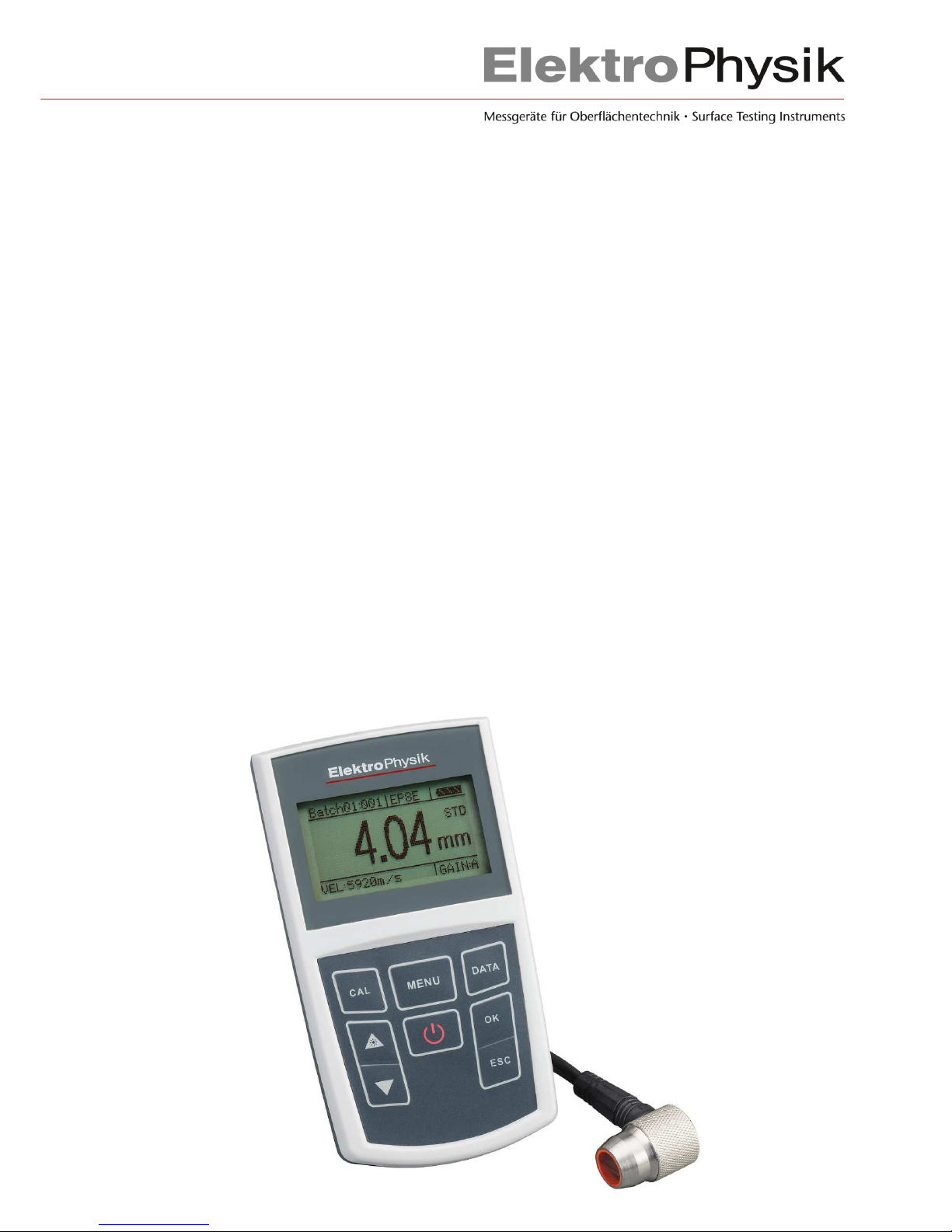
Technical Manual and
Operating Instructions
Ultrasonic Thickness Gauges
MiniTest 430 / 440
Page 2

Important Note
In ultrasonic thickness measurement it is inherent to the measuring procedure that the gauge might
use the second echo rather than the first one reflected from the material being measured. This may
result in a thickness reading TWICE as high than the actual thickness.
When measuring through extremely thick coatings in the echo-echo mode, it may occur that the
thickness of coating layer is measured instead of the wall thickness that actually was intended to
be measured.
The responsibility for proper use of the gauge and recognition of this phenomenon rests solely with
the user of the gauge.
© Editon 1, 08/2014
Version 1.0
Subject to change without notice.
ElektroPhysik
Dr. Steingroever GmbH & Co. KG
Pasteurstr. 15
50735 Koeln, Germany
Phone: +49 221 752040
Fax : +49 221 7520467
Internet: http://www.elektrophysik.com/
Mail: info@elektrophysik.com
Page 3

Table of Contents
1. Introduction ............................................................................................................................... 5
1.1 Important Notes on Wall Thickness Measurement ................................................................ 5
Prerequisites for the use of ultrasonic wall thickness gauges ................................................. 5
1.1.1 Training of the Person in Charge of Testing .................................................................. 6
1.1.2 Limitations to Ultrasonic Testing.................................................................................... 6
1.1.2.1 Ultrasonic Wall Thickness Testing ........................................................................... 6
1.1.2.2 Influence of the Material to be tested ....................................................................... 7
1.1.2.3 Influence of Changes in Temperature ...................................................................... 7
1.1.2.4 Measurement of the Residual Wall Thickness ......................................................... 7
1.1.2.5 How to use the Couplant ......................................................................................... 7
1.1.2.6 Duplication of Reading ............................................................................................. 8
2. Technical Specifications .......................................................................................................... 9
3. Measuring Principle ................................................................................................................ 10
4. Description of the Gauge and Schedule of Supply ............................................................... 11
4.1 Description of the Gauge (Front and back Side) .................................................................. 11
4.2 Supply Schedule ................................................................................................................. 11
4.2 Display ................................................................................................................................ 12
4.3 Keyboard ............................................................................................................................. 13
5. Preparing Measurement ......................................................................................................... 14
5.1 Preparing the Gauge ........................................................................................................... 14
5.2 Selection of the Transducer ................................................................................................. 14
5.3 Preparing the Surface of Measuring Object ......................................................................... 15
6. Operation ................................................................................................................................. 16
6.1 Switch ON ........................................................................................................................... 16
6.2 Taking Readings ................................................................................................................. 16
6.3 Calibration ........................................................................................................................... 17
6.3.1 Calibration ................................................................................................................... 17
How to calibrate MiniTest 430 / 440 ................................................................................... 17
6.3.2 Determination of the Sound Velocity ........................................................................... 17
6.3.2.1 How to determine the Sound Velocity....................................................................... 18
6.3.3 Calibration of the Transducer.................................................................................... 18
6.4 User Menu .......................................................................................................................... 19
6.4.1 Measuring Mode (Meas. Mode) .................................................................................. 19
6.4.1.1 MiniTest 430 .......................................................................................................... 19
6.4.1.2 Operating modes of MiniTest 440 .......................................................................... 21
6.4.1.2.1 I-E mode ............................................................................................................. 21
6.4.1.3.2 Echo-Echo mode ................................................................................................ 22
6.4.2 Sound Velocity ............................................................................................................ 23
6.4.2.1 Materials ................................................................................................................ 23
6.4.2.2 Setting Sound Velocity (vel. custom) ..................................................................... 24
6.4.3 Measuring Unit ............................................................................................................ 25
6.4.4. Data Memory ............................................................................................................. 25
6.4.4.1 Select a Batch (MiniTest 430 / 440) ....................................................................... 26
6.4.4.2 Delete a Batch (MiniTest 430 / 440) ....................................................................... 26
6.4.5 Gain Setting ................................................................................................................ 27
6.4.6 Switch Off Mode .......................................................................................................... 27
6.4.7 Contrast ...................................................................................................................... 28
6.4.8 Language .................................................................................................................... 28
6.4.9 Gauge Data ................................................................................................................ 28
6.4.10 Standard Setting ....................................................................................................... 28
6.5 Data Processing .................................................................................................................. 28
Page 4

6.6 Storing Readings ................................................................................................................. 28
7. Measuring Technology ........................................................................................................... 29
7.1 Measuring Methods ............................................................................................................. 29
7.2 Measurement on Pipes and Tubes ...................................................................................... 29
8. Maintenance and Precautions ................................................................................................ 30
8.1 Power Check ....................................................................................................................... 30
8.2 Precautions ......................................................................................................................... 30
8.2.1 General Precautions ................................................................................................... 30
8.2.2 Precautions to take during Measurement .................................................................... 30
9. Table of Materials and their typical Sound Velocity (Longitudinal Wave) ..................... 31
10. Safety Notes .......................................................................................................................... 32
11. Declaration of Conformity .................................................................................................... 33
11. After-Sales Service ............................................................................................................... 33
13. Change History ..................................................................................................................... 33
Page 5

5
1. Introduction
The MiniTest 420 and 440 model are non-destructive ultrasonic thickness gauges for portable or
stationary use. Working according to the ultrasonic principle it enables quick and easy measurement
of wall thickness. It can also be used for the measurement of the sound velocity of metals and various
other materials.
Prior to use, please read the operating instructions carefully in order to get familiar with the use
and all functionalities of the MiniTest 430/440 gauges.
Even if you are already familiar with measurement according to the ultrasonic principle, it is highly
recommended to read section 1.1 carefully. This section provides important information on the
limitations to and conditions for reliable wall thickness measurement such as technical training,
required knowledge on the specific requirements for testing and the selection of a suitable test
equipment.
The gauge is easy to use. To enable its quick use, please read the sections below to get familiar
with the preparatory requirements and basic functions.
1.1 Important Notes on Wall Thickness Measurement
Before using the wall thickness gauge, please read the following instructions
carefully. Make sure to fully understand and follow the instructions in order to
avoid errors that might lead to erratic readings. Any decisions based on erratic
readings may cause damage to property or personal injury.
Prerequisites for the use of ultrasonic wall thickness gauges
This manual contains essential information on how to operate your measurement device. In
addition, there are a number of other factors to influence measurement. A detailed description of all
such factors would be beyond the scope of this manual. For that reason, this manual is limited to
the three most important requirements for reliable ultrasonic wall thickness measurement:
adequate training of the person in charge of measurement
fundamental knowledge on the specific requirements on and limitations to the measuring
technique used for testing
choice of a suitable measuring equipment
Page 6

6
1.1.1 Training of the Person in Charge of Testing
The proper use of ultrasonic test equipment requires an adequate training in the field of ultrasonic
wall thickness testing. Such training should include the following subjects:
theory of sound propagation in materials
effect of the sound velocity inherent to material to be tested
behaviour of sound waves at the interfaces between different materials
propagation of the sound beam in the material
effect of the surface quality of the material to be tested
Insufficient knowledge on the above topics may result in erratic readings and thus lead to
unforeseen consequences. For more information on the availability of training opportunities for
examiners in ultrasonic testing, qualifications and certificates, please contact your national NDT
partner, or, in Germany Deutschen Gesellschaft für Zerstörungsfreie Prüfung e.V., Motardstraße
54, D-13629 Berlin.
1.1.2 Limitations to Ultrasonic Testing
The results obtained from measurement solely relate to areas of the measuring object that have
been targeted by the sound beam. Conclusions to other areas of the measurement object are not
admissible. They are only allowed if extensive experience on the process of manufacture of the
measuring objects is available and if appropriate methods of statistical evaluation can be applied.
It should be taken into consideration that the ultrasound beam might be completely reflected by
interfaces being present in the measuring object so that deeper reflection points will not be
reached by the ultrasound any more. For that reason it must be ensured that all areas of the
measuring objects to be measured can be reached by the sound beam.
1.1.2.1 Ultrasonic Wall Thickness Testing
Ultrasonic wall thickness measurement is based on the measurement of travel times of sound
pulses in the object to be measured. For reliable wall thickness measurement it is presumed on the
assumption that the velocity in the measuring object remains constant. Generally, this is given for
the majority of work-pieces made of steel. Even if they include different alloy components, the
sound velocity changes will be small enough to be neglected (unless high-precision measurement
is required).
Page 7

7
In other materials such as non-ferrous metals or plastics, the sound velocities are subject to major
changes that might impair the measuring accuracy.
1.1.2.2 Influence of the Material to be tested
Material discontinuities may lead to strong variations of the sound velocity within a measuring
object. In such case, an average sound velocity should be used for testing.
However, the best results will obtained when calibrating the gauge by means of a reference
sample. This sample must be made of the same material as the object to be measured and should
exhibit plane parallel surfaces. Its thickness should equal the maximum thickness of the later
object to be measured. Please note that any heat treatment might considerably change the sound
velocity and thus influence the measuring precision accordingly.
If dramatic changes of the sound velocity are to be expected, it is recommended to readjust the
sound velocity within shorter time intervals. This is to avoid erratic readings.
1.1.2.3 Influence of Changes in Temperature
The sound velocity is also influenced by the temperature prevailing in the material. If the gauge has
been adjusted to a “cold” reference sample and wall thickness measurement is made on a “warm”
object, major measuring errors are very likely to occur.
To avoid such measuring errors, it is recommended to use a temperature-adapted reference
sample for adjusting the gauge. Another option would be to correct for the applicable temperature
influence by means of the sound velocity/temperature correction table.
1.1.2.4 Measurement of the Residual Wall Thickness
Measuring the residual wall thickness of internally eroded or corroded objects such as tubes,
containers or reaction vessels makes it necessary to choose a most suitable test equipment and to
handle the sensor with utmost care. In addition, the nominal wall thickness as well as the
suspected degree of wall thickness loss should be known.
1.1.2.5 How to use the Couplant
Make sure the user is familiar with the use of couplant. For each measurement, the couplant must
be applied evenly over the surface of the measuring object. Any variations in couplant layer thickness
will influence measuring accuracy. Both, adjustment of the gauge and wall thickness measurement
must be made under the same coupling conditions. Make sure to use a quantity of couplant as small
as possible and to apply a constant contact pressure of the sensor.
Page 8

8
When measuring on curved surfaces such as pipes or tubes make sure the coupling of the
transceiver is made properly. The acoustic layer interface of the transceiver must be aligned so as
to form a right angle to the axis of curvature of sample (longitudinal axis of tube). For small tube
diameters it is recommended to carry out two measurements: one with the layer interface in vertical
position to the longitudinal axis of tube, another one in parallel position to the longitudinal axis of
tube. The smaller of the two readings obtained should be used as the correct one for this measuring
spot.
(senkrecht = vertical)
1.1.2.6 Duplication of Reading
Do not measure in a range lower than the measuring range specified for the sensor. In such case,
the first back wall echo would not be strong enough for being processed whereas the amplitude of
the second one would be strong enough to be processed accordingly. As a result, the reading
obtained would be twice the actual wall thickness. In order to avoid such errors when measuring at
the limit of the measuring range it is recommended to verify results by using another sensor.
In critical cases, it is recommended to use display screen equipment to provide additional information
on the echo curve.
.
Page 9

9
2. Technical Specifications
Display screen: 128 x 64 pixel dot matrix LC display, backlit
Digital display: four-digits
Measuring range: 0.65 mm ... 500.0 mm (steel) depending on transducer
Display resolution:
0.1 mm (if readings > 100 mm)
0.01 mm (if readings < 100 mm)
Measuring accuracy:
0.65 mm... 9.99 mm: ± 0.04 mm
10 mm… 99.99 mm: ± (0.04 mm + 0.1% of reading)
100 mm... 500 mm: ± (0.3 % of reading)
Sound velocity: 1000...9999 m/s
Data memory: 10 batches for a maximum of 500 readings per batch
Measuring frequency:
2 readings/second in the standard mode
10 readings/second in the high-performance mode (scan)
Zero point calibration: automatic
Auto switch-off: 2 minutes, 5 minutes or shut down manually
Power supply: 2 x AA battery, battery life 80 h in continuous operation
Operating temperature: -20°C ... 50°C
Storage temperature: -25°C ... 60°C
Dimensions: 130 x 73 x 24 mm
Weight: 190 g (without batteries)
Options Transducers U2.0, U5.0, U7.5, U10.0, U5.0HT
Page 10

10
3. Measuring Principle
The ultrasonic sensor head emits an ultrasonic signal to travel through the sensor head, the
couplant and finally to the measuring object. A portion of the ultrasound signal is reflected from the
surface of measuring object, another one is reflected from the opposite side of the object when
travelling back. The sensor receives both echoes. The wall thickness is calculated according to the
exact time of travel of pulse and shown as reading on display.
Page 11

11
4. Description of the Gauge and Schedule of Supply
4.1 Description of the Gauge (Front and back Side)
1. display
2. keyboard
3. battery compartment (back panel)
4. name plate (back panel)
5. transducer socket (Identify PIN)
6. USB interface (MiniTest 430 / 440)
4.2 Supply Schedule
1. 1 x plastics carrying case
2. 1 x MiniTest gauge (model 430 or 440)
3. 1 x ultrasonic transducer (U5.0 for MiniTest 430; U5.0E for MiniTest 440)
4. 1 x couplant (gel, 200ml)
5. 1 x operating instructions (German / English / French)
6. 1 x CD with data transfer software
7. 1 x USB connecting cable
8. 2 x 1,5V (AA) batteries
Page 12

12
4.2 Display
1. active batch and number or readings stored in this batch
2. transducer model
3. battery state
fully charged
empty
4. measuring mode
5. measuring icon and measuring unit
6. gain mode of amplifier selection (A = Auto, L= Low , M = Medium, H = High).
7. sound velocity selection
8. current reading
①
②
⑤
⑥
④
⑧
⑦
Page 13

13
4.3 Keyboard
ON / OFF button
Menu key
Press to enter the operating menu
Arrow UP/DOWN keys
Press UP/DOWN to scroll through the different
menu options.
Press arrow UP to enable / disable the backlight.
OK/ESC key
Press OK to confirm a selection in the menu.
Press ESC to quit the menu.
CAL key
Quick access for sound velocity calibration (it is
required the wall thickness is known).
Data memory short-cut key
Page 14

14
5. Preparing Measurement
5.1 Preparing the Gauge
Please check gauge and accessories immediately upon receipt. For the supply schedule, please
refer to section 4.1.2 of this manual. Please contact your supplier in case delivery is not complete
or does not comply with the supply schedule you have ordered. Any damage of the gauge should
be reported upon delivery. Do not use the gauge in case it seems to be damaged!
5.2 Selection of the Transducer
Type Frequency Measuring range Temperature
U2.0 2,0 MHz 2.0 mm...500 mm < 60°C
U5.0E 5,0 MHz E-E 3.0 mm...25 mm
I-E 1.0 mm...200 mm
< 60°C
U5.0 5,0 MHz 0.8 mm...300 mm < 60°C
U5.0HT 5,0 MHz 3.0 mm...200 mm < 350°C
U7.5 7,5 MHz 0.65 mm...50 mm < 60°C
U10.0 10,0 MHz 0.65 mm…20 mm < 60°C
Page 15

15
Make sure to select a suitable transducer according to the thickness of your measuring object.
The transducer used for measurement must be in a good condition. Make sure transducer tip and
coupling surface are not worn off. The measuring range of transducer should cover the complete
wall thickness range to be measured (application range). The temperature of measuring object
must not exceed the temperature range specified for the transducer you have selected.
Transducer type Application
U5.0:
(5.0 MHz)
Standard transducer for MiniTest 430 to cover a wide
range of applications such as measurement on
- flat surfaces
- large curvature radii
- objects with a thickness > 50 mm
U5.0E
(5.0 MHz)
Standard transducer for MiniTest 440. When connected
to MiniTest 440, this transducer is able to measure in the
E-E mode the wall thickness of steel through a coating
applied to the steel.
U2.0
(2.0 MHz)
Rough surfaces, such as on cast components
U5.0HT
(5 MHz)
Suitable for temperatures < 350°C
U7.5
(7,5 MHz)
Thin wall thickness and small curvature radius
U10.0
(10 MHz)
Thin wall thickness and small curvature radius (small
geometries)
U2.0
(2.0 MHz)
Rough surfaces, such as on cast components
5.3 Preparing the Surface of Measuring Object
Very rough and/or corroded surfaces should be pre-treated as follows:
1. Smoothen the surface by grinding, polishing or filing or use a high-viscosity couplant.
2. Apply some couplant to the surface of measuring object.
3. Take several readings around the measuring spot.
Page 16

16
6. Operation
6.1 Switch ON
Connect the transducer to the gauge socket. Press the ON/OFF button to switch on. The
following appears on display:
If no transducer has been connected prior to switch ON, the following message will appear:
”Please insert the transducer”. Insert the transducer into the gauge socket and wait for the
measuring status to appear.
Please make sure to connect solely original ElektroPhysik transducers suitable for
MiniTest 430 / 440. Otherwise, the gauge will not work correctly and the error
message “ERROR” will appear.
6.2 Taking Readings
There are two options to access the measuring mode:
1. Connect transducer and switch on the gauge.
2. From the menu you can press ESC and go back to the measuring mode.
Once you have put the transducer onto the measuring object, the display will show the
measuring icon to indicate the coupling action. Once the reading has stabilized, you
can detach the transducer from the measuring object. Remove the transducer in a
quick action. The last reading taken appears on display.
Page 17

17
6.3 Calibration
Errors occurring during the first operating steps might be due to the following reasons:
• Transducer failure or strong variations in temperature
• System error caused by base unit / transducer incompatibility
• Computing error caused by sound velocity/material setting error
For troubleshooting please proceed as follows:
Press -key followed by or to select a suitable option.
6.3.1 Calibration
How to calibrate MiniTest 430 / 440
Worn off transducer or the use of different transducer models as well as the ambient temperature
may lead to erratic readings. To compensate for such errors, the both models feature an
“automatic calibration”.
Important note:
Prior to calibration make sure the transducer tip is clean and free from any residual couplant or
other dirt particles that might impair measurement and thus the calibration accuracy. In case
temperature varies strongly during measurement, it is recommended to use the calibration function
more frequently in order to ensure accuracy of measurement.
6.3.2 Determination of the Sound Velocity
The sound velocity in the measuring object depends on the material the object is made of. In
addition, measuring objects might exhibit material irregularities (if produced in different product
batches). As a result, the sound velocity might vary according to the sample to be tested. To
prevent measuring errors based on divergent sound velocities, it is absolutely necessary to
determine the precise sound velocity of an object unless measuring errors are small enough to be
neglected. To calibrate the gauge to the correct sound velocity of an object, the function “Sound
velocity” is available.
Page 18

18
6.3.2.1 How to determine the Sound Velocity
1. Select a stored sound velocity or set the gauge to a sound velocity as close as possible to
the sound velocity of the material to be measured.
2. Take a sample of a defined thickness as close as possible to the thickness of the later
measuring object. If no such sample is available, take your measuring object and measure
its thickness using a caliper or another measuring tool.
3. Now use MiniTest 430 or 440 to measure the sample in order to get a thickness value.
4. First press -key to go to the “Sound velocity”. Then press or in order to
adjust to the thickness reading you have measured and get the correct sound velocity
accordingly.
5. Adjust the sound velocity so that the material thickness shown on display corresponds to
the measured thickness of sample.
6. Re-measure the sample and check the deviation between reading and actual thickness. If
both values are identical, the sound velocity is correct for this material.
6.3.3 Calibration of the Transducer
The transducer calibration function is to be used to compensate for errors or system errors that
cannot be remedied by “Automatic calibration”. The cause of such error might be for instance a
transducer change. First make sure the error is not due the setting of an unsuitable sound velocity.
To carry out the transducer calibration please proceed as follows:
1. Adjust the gauge to the sound velocity 5920 m/s.
2. Take a reading on test block supplied with the gauge and take. The reading obtained
should be 4.00 mm ± 0.01 mm. If the reading obtained differs from that value, press the
-key. Then press or . Choose “Transducer calibration“ and press OK to
confirm.
Now use arrow keys or to adjust the reading you obtained to the thickness of
test block, i.e. 4.00 mm. Press OK to confirm the value. Then press ESC to go to the
measuring mode.
Page 19

19
6.4 User Menu
Press key to go to the main menu. Use arrow keys or to scroll up/down the menu
items.
Once your selected item appear press OK to confirm.
Press ESC to quit the menu and to go to the measuring mode.
MiniTest 430 / 440
6.4.1 Measuring Mode (Meas. Mode)
6.4.1.1 MiniTest 430
The gauge offers 5 different measuring modes. Please select the correct mode according to your
requirements and measuring conditions.
Standard mode: The current reading is shown. This mode applies if you are satisfied with the
standard measuring needs.
Minimum mode: In this mode, the lowest values is shown during measurement. This mode is
recommended for curved surfaces or if it is required to indicate the lowest thickness values. This
would be a typical application of tube measurement.
Important note: This mode is NOT recommended for cast iron or Aluminium alloys.
Page 20

20
Difference mode: If you have adjusted a set point previously, this mode will indicate the difference
between the current reading and set point. This mode is particularly suitable for quality inspection
and if it is required to identify the products within the admissible thickness tolerance range.
Alarm mode (Limitation): In this mode, a visual alarm will be given once the upper or lower limit
(if set previously) has been exceeded. This mode enables a quick and easy checking of readings
so that a permanent monitoring of readings will not be necessary. In practical operation, this mode
is more frequently used than the “Difference mode“.
Scan mode (high-performance mode): This mode is particularly suited for measurement on hightemperature samples.
The different modes are shown on display as follows:
Page 21

21
6.4.1.2 Operating modes of MiniTest 440
This gauge offers two different operating modes:
• I-E: Impulse-Echo mode (pulse-echo)
Available with all transducer models.
• E-E: Echo-Echo mode
Only available with the U5.0E transducer for
the measurement of wall thickness through a
coating.
6.4.1.2.1 I-E mode
The pulse-echo (I-E) mode offers five different measuring modes. Please select the correct mode
according to your measuring requirements and conditions.
Standard mode: The current reading is shown. This mode applies if you are satisfied with the
standard measuring needs.
Minimum mode: In this mode, the lowest values is shown during measurement. This mode is
recommended for curved surfaces or if it is required to indicate the lowest thickness values. This
would be a typical application of tube measurement.
Important note: This mode is NOT recommended for cast iron or Aluminium alloys.
Difference mode: If you have adjusted a set point previously, this mode will indicate the difference
between the current reading and set point. This mode is particularly suitable for quality inspection
and if it is required to identify the products within the admissible thickness tolerance range.
Alarm mode (Limitation): In this mode, a visual alarm will be given once the upper or lower limit
(if set previously) has been exceeded. This mode enables a quick and easy checking of readings
so that a permanent monitoring of readings will not be necessary. In practical operation, this mode
is more frequently used than the “Difference mode“.
Scan mode (high-performance mode): This mode is particularly suited for measurement on hightemperature samples.
Page 22

22
The different modes are shown on display as follows:
6.4.1.3.2 Echo-Echo mode
The Echo-Echo (E-E) mode is able to measure between two successive back-wall echoes. This
allows to measure the actual wall thickness through a coating.
Please note! This function for measuring the wall thickness through a coating is only available with
the U5.0E transducer model.
Page 23

23
6.4.2 Sound Velocity
The correct selection of the sound velocity is vital for accurate measurement. Different materials
exhibit different sound velocities at which the ultrasound travels through. If you select the wrong
sound velocity, measurement will be erroneous.
There are two ways to select the material's sound velocity: material selection and sound velocity
setting.
Materials:
You select the sound velocity according to the material and the pre-set sound velocity.
Vel. Custom:
The sound velocity is user adjustable.
6.4.2.1 Materials
If the material and its specific sound velocity are known, users can select the sound velocity from
the gauge accordingly. Nine (9) different velocities are stored in the gauge and can be selected by
the user: Aluminium, titanium, steel, stainless steel, glass, copper, brass, polystyrene and nylon.
Note: The 9 velocities are just theoretical ones. To increase measuring accuracy, please
refer to “Setting Sound Velocity” under 6.4.2.2. The sound velocity functionality enables
you to set the gauge to the correct sound velocity of a material.
Page 24

24
6.4.2.2 Setting Sound Velocity (vel. custom)
If none of the sound velocities as stored for the 9 materials meet your requirements, the sound
velocity can be adjusted individually. Please refer to the table given in the appendix, section 9 of
this manual. Use this table to set to the correct sound velocity as requested.
Note: For more accurate measurements, please refer to section 6.3.2.1 “How to determine
the sound velocity”.
Page 25

25
6.4.3 Measuring Unit
Read-out resolution and measuring unit are user-adjustable. When selecting “High resolution”, the
surface of measuring sample should smooth in order to obtain accurate readings.
Low resolution High resolution
Note:
For using the U5.0HT or U2.0 transducers, the following setting is recommended:
0.1 mm / 0.01 in.
6.4.4. Data Memory
Both models MiniTest 430 and 440 feature a data memory for storing a maximum of 10 batches
with 500 readings storable per batch. Total data memory capacity is 5000 readings.
A batch memory includes the following data: readings, type of transducer head, sound velocity and
selected measuring mode.
A batch can be selected and/or deleted.
Page 26

26
6.4.4.1 Select a Batch (MiniTest 430 / 440)
Use this function to select a batch according to your requirements. Once a batch selected, it will
become active and all readings taken will be stored to this batch.
Below a batch that has been selected but no readings have been taken so far.
Below a batch that has been selected and to which readings have been stored.
Please note:
If you have selected a batch to which readings have been stored and then change the transducer
model or measuring mode, the following message will appear “Change batch”. In such case the
batch is not available as it has been defined with another transducer model and/or measuring
mode. Please select another batch that matches the transducer model/measuring mode you are
currently using.
6.4.4.2 Delete a Batch (MiniTest 430 / 440)
Use this function to delete a batch. First select the batch to be deleted, then confirm deletion.
Please note:
If you delete a batch, all data stored to this batch will be deleted and cannot be restored. For that
reason it is recommended to previously safe the data to be deleted to your PC.
Page 27

27
6.4.5 Gain Setting
Measuring accuracy and consistency of readings are influenced by the material to be measured and
its composition. In order to meet the requirements for accurate measurement, it is requested to set
the gauge according to the special characteristics of a sample and measuring conditions.
For the majority of materials and conditions the auto gain adjustment will be sufficient whereas some
specific measuring tasks might require specific gauge settings. For gain setting, the gauge offers
four different working modes: Auto, Low, Medium and High.
Auto: This mode matches different transducers and is suitable for the majority of
measuring requirements.
Low: Suitable for high scattering and materials exhibiting low attenuation properties.
Medium: Suitable for a large field of applications.
High: Suitable for high attenuation materials.
6.4.6 Switch Off Mode
Both models, MiniTest 430 and 440, offer three different service modes:
• after 2 min: automatic switch off after two minutes of idle state
• after 5 min: automatic switch off after five minutes of idle state
• disable: automatic switch off is disabled, the gauge is in continuous operation
Note:
When the automatic switch off has been disabled, make sure to switch off the gauge
manually after use in order to save power.
Page 28

28
6.4.7 Contrast
The gauge offers 6 levels for contrast setting.
6.4.8 Language
The gauge offers the following languages: Chinese, English, German, French.
6.4.9 Gauge Data
This option allows you to read out the following data:
• Gauge model
• Serial of gauge
• Transducer type
• Serial of transducer
• Software version of gauge
6.4.10 Standard Setting
For trouble shooting, it is recommended to use this function to reset the gauge to the factory settings.
6.5 Data Processing
Both models, MiniTest 430 and 440, offer two different data processing options.
Press the -key to get access to the two options:
• Data read: If you have selected a batch, the stored data will immediately be displayed on
the screen.
• Data transfer: Via the USB interface, the stored data will be transferred to a PC.
Please note:
For a detailed description on data transfer to a PC via the USB interface please refer to the CD
supplied with the gauge.
6.6 Storing Readings
Once you have selected a batch, readings can be stored to the gauge as follows:
1. Make sure readings have been taken correctly.
2. Once you lift the transducer from the sample, press OK to store the current reading.
Page 29

29
7. Measuring Technology
7.1 Measuring Methods
The gauge provides four different measuring methods.
1. Single point measurement: use the transducer to measure any point of the measuring object.
The reading shown is the thickness value.
2. Two point measurement (on cylindrical parts, e. g. pipes and tubs): perform two measurements
on the same point of the surface of object. During the second measurement, make sure the
black line on the transducer head (layer to separate the transmitter and receiver part of
transducer) is oriented in a 90 degree position to the axis of the pipe or tube. The smaller of the
two readings obtained represents the thickness value.
3. Multiple point measurement: perform several measurements on the measuring object within a
range of about 30mm in diameter. The smaller of the readings represents the thickness of the
measuring object.
4. Continuous measuring method: use the single point measuring method and take readings
continuously along the designated route. The intervals between measurements should be less
than 5mm. The smallest reading represents the thickness of the measuring object.
7.2 Measurement on Pipes and Tubes
During measurement, make sure to position the transducer’s separating layer perpendicular or
parallel to the longitudinal line of the pipe or tube. For pipes and tubes of large diameters, the
separating layer of transducer should be perpendicular to the longitudinal line the measuring object
whereas for small diameters, it is recommended to carry out measurement in both directions,
perpendicular and parallel to the longitudinal line of the measuring object. The minimum readout
represents the thickness of object at this measuring spot.
Page 30

30
perpendicular parallel
8. Maintenance and Precautions
8.1 Power Check
When the power is low, the low battery indicator appears. At this moment, users should replace the
battery in time, or it will affect the measuring accuracy. Please note that the backlight will use
additional power. If the battery is too low, the backlight will automatically shut down in order to ensure
reliable service.
For use on site it is recommended to make available a set of replacement batteries.
Note: If the gauge is not in use for a longer period of time, make sure to remove the batteries
in order to prevent battery leakage and damage to the gauge.
8.2 Precautions
8.2.1 General Precautions
Keep the gauge away from strong vibrations. Do not stock in an environment with increased levels
of air humidity. To prevent cable damage, plug or unplug the transducer by holding the cable jacket.
8.2.2 Precautions to take during Measurement
1. Once you place the transducer on the measuring object, the measuring symbol appears on
display (arrow down) to indicate the coupling action. As soon as the reading has stabilized,
you can lift the transducer from the measuring object.
2. Make sure to remove the transducer immediately after a reading has been taken successfully
as putting the transducer down again might cause erratic readings if big amounts of coupling
agent are placed on the measuring object.
3. Please note: a worn off transducer will lead to unstable and erratic readings and should be
replaced by a new one.
Page 31

31
9. Table of Materials and their typical Sound Velocity
(Longitudinal Wave)
Material
Sound velocity
in/µs m/s
Air 0,013 330
Aluminium 0,250 6300
Aluminium oxide 0,390 9900
Beryllium 0,510 12900
Boron carbide 0,430 11000
Brass 0,170 4300
Cadmium 0,110 2800
Cast iron 0,180 4600
Crown glass 0,210 5300
Cupper 0,180 4700
Glycerine 0,075 1900
Gold 0,130 3200
Ice 0,160 4000
Inconel 0,220 5700
Iron 0,230 5900
Lead 0,085 2200
Magnesium 0,230 5800
Mercury 0,057 1400
Molybdenum 0,250 6300
Monel 0,210 5400
Neoprene 0,063 1600
Nickel 0,220 5600
Nylon, 6.6 0,100 2600
Oil (SAE 30) 0,067 1700
Platinum 0,130 3300
Plexiglass 0,110 1700
Polyethylene 0,070 1900
Polystyrene 0,0930 2400
Polyurethane 0,0700 1900
Quartz 0,230 5800
Rubber, Butyl 0,070 1800
Silver 0,140 3600
Stahl stainless 0,228 5800
Steel, commercial 0,233 5920
Teflon 0,060 1400
Tin 0,130 3300
Titan 0,240 6100
Tungsten 0,200 5200
Uranium 0,130 3400
Water 0,584 1480
Zinc 0,170 4200
Page 32

32
Please note: The actual sound velocities depend on the temperature, composition and treatment of
a material. Especially metal alloys or plastic materials may exhibit strong variations. For that
reason, all values stated in the table are approximate ones.
10. Safety Notes
Safe operation will be ensured as far as the instructions and notes in this manual and on the
gauge are observed.
Prior to any installation work the power supply must be cut.
Please do only use original spare parts or accessories.
Storage batteries and accessories
Make sure to use only original accessories and batteries supplied /
recommended by the manufacturer of the gauge. Connect only to
compatible peripheral devices.
Connecting other
devices
If you connect the gauge to any other device, please refer to the
respective instructions manual of such device for detailed information on
safety issues. Do only connect original accessories.
Keep away from water
The measuring unit is not waterproof. Keep in a dry place.
Keep away from explosion-hazardous area.
Approved after
-
sales service
The gauge may only be repaired by approved and qualified after-sales
service personnel.
Medical facilities
Please ask for permission before using the gauge in medical facilities.
Das Bild kann zurzeit nicht angezeigt werden.
Page 33

33
11. Declaration of Conformity
We herewith declare that the gauges MiniTest 430 and MiniTest 440 are in conformity with the
provisions of directive 89/ 336 / EEC (Electromagnetic compatibility), in Germany: EMVG (Gesetz
über die elektromagnetische Verträglichkeit) of November, 9th, 1992.
11. After-Sales Service
The MiniTest 430 and MiniTest 440 gauges are manufactured according to state-of-the-art
production methods under the use of high-quality components. Careful production controls along
with a Certified Quality Management according to DIN EN ISO 9001 ensure optimum product
quality.
Should you nevertheless notice any error, please contact the ElektroPhysik after-sales-service and
advise your problem.
Please retain the original packing for future transportation needs if a repair should become
necessary.
For more detailed information on the use, applications, service or technical data, please contact
your local agent or ElektroPhysik:
ElektroPhysik
Dr. Steingroever GmbH & Co. KG
Pasteurstr. 15
50735 Koeln, Germany
Tel.: +49 221 75204-0
Fax: +49 221 75204-67
E-Mail: info@elektrophysik.com
Please refer to our website for the local representative of ElektroPhysik in your country:
www.elektrophysik.com
13. Change History
This section is to backtrack any changes and modifications to this manual. If no changes are
available, this section shall remain empty.
 Loading...