

Page 1

MiniTest 403
Technical Reference and Operating Manual
Advancing with Technology ElektroPhysik
Page 2

© Print ref. # B-26-A1
Subject to change without notice
ElektroPhysik Dr. S teingroever GmbH & Co. KG
Pasteurstr. 15
50735 Köln
Deutschland
Tel.: +49 221 75204-0
Fax.: +49 221 75204-67
web: www.elektrophysik.com
mail: info@elektrophysik.com
Disclaimer
Inherent in ultrasonic thickness measurement is the
possibility that the instrument will use the second rather
than the first echo from the back surface of the material
being measured. This may result in a thickness reading
that is TWICE what it should be. Responsibility for proper use of the instrument and recognition of this
phenomenon rests solely with the user of the instrument.
Page 3

ElektroPhysik E-i
Contents
Contents
1. Introduction........................................E-1
1.2 Supply Schedule .....................................E-2
2. Operation ............................................E-2
2.1 Keypad .....................................................E-2
2.2 Display......................................................E-4
3. Transducer .........................................E-7
4. Making Measurements ......................E-8
4.1 Condition and Preparation of Surfaces.... E-9
4.2 Probe Zero .............................................E-10
5. Calibration ........................................E-11
5.1 Calibration to a known thickness ........ E-11
5.2 Calibration to a known velocity ..........E-12
5.3 Two Point Calibration ........................... E-13
6. Scan Mode....................................... E-14
7. Transducer Selection...................... E-14
8. Product Specifications................... E-16
9. Application Notes ........................... E-17
9.1 Measuring Pipe and Tubing ................. E-17
9.2 Measuring Hot Surfaces .......................E-17
9.3 Measuring Laminated Materials.......... E-18
10.Sound Velocities............................. E-19
11. Af ter-Sales Service ......................... E-21
Index...................................................... E-22
Page 4

ElektroPhysik E-1
1. Introduction
The MiniTest 403 is a precision Ultrasonic Micrometer.
capable of measuring the thickness of various materials
with accuracy as high as ± 0.01mm or ± 0.001 inches.
The principle advantage of ultrasonic measurement over
traditional methods is that ultrasonic measurements can
be performed with access to only one side of the material being measured.
This manual is presented in three sections. The first
section covers operation of the MiniTest 403 and
explains the keypad controls and display. The second
section provides guidelines in selecting a transducer for
a specific application. The last section provides
application notes and a table of sound velocity values
for various materials.
ElektroPhysik maintains a customer support resource
in order to assist users with questions or difficulties not
covered in this manual. Customer support may be
reached at any of the following:
Introduction
ElektroPhysik
Pasteurstr. 15
D-50735 Köln
Tel.: +49 (0) 221 75204-0
Fax: +49 (0) 221 75204-67
www.elektrophysik.com
info@elektrophysik.com
ElektroPhysik USA
770 West Algonquin Rd.
Arlington Heights IL 60005
Phone: +1 847 437-6616
Fax: +1 847 437-0053
www.elektrophysik.com
epusa@elektrophysik.com
Page 5

E-2 ElektroPhysik
1.2 Supply Schedule
· Plastics carrying case
· Gauge with transducer
· 1 bottle coupling fluid
· 2 x AA 1,5V alkaline batteries
· Instruction manual (English/German)
· Calibration certificate NIST 04-25-174-A and
04-28146-A
2. Operation
The MINITEST 403 interacts with the operator through
the membrane keypad and the LCD display. The
functions of the various keys on the keypad are detailed
below, followed by an explanation of the display and its
various symbols.
Introduction
2.1 Keypad
ON/OFF Key
This key is used to turn the MINITEST 403 on and off.
When the gauge is turned ON, it will first perform a brief
display test by illuminating all of the segments in the
display.
After one second, the gauge will display the internal
software version number. After displaying the version
number, the display will show „0.000“ (or „0.00“ if using
metric units), indicating the gauge is ready for use.
Page 6
ElektroPhysik E-3
The MINITEST 403 is turned OFF by pressing the ON/
OFF key.
The gauge has a special memory that retains all of its
settings even when the power is off.
The gauge also features an auto-powerdown mode
designed to conserve battery life. If the gauge is idle for
5 minutes, it will turn itself
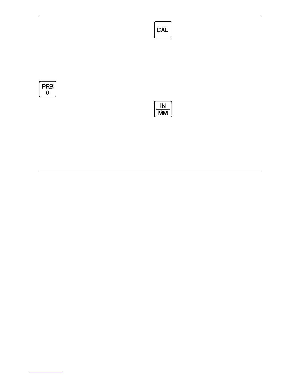
PRB-0 Key
The PRB-0 key is used to „zero“ the MINITEST 403 in
much the same way that a mechanical micrometer is
zeroed. If the gauge is not zeroed correctly, all of the
measurements that the gauge makes may be in error
by some fixed value. Refer to Section „Performing a
probe Zero“ for an explanation of this important
procedure.
Keypad
CAL Key
The CAL key is used to enter and exit the MINITEST
403’s calibration mode. This mode is used to adjust the
sound-velocity value that the MINITEST 403 will use
when calculating thickness. The gauge will either
calculate the sound-velocity from a sample of the material being measured, or allow a known velocity value to
be entered directly. Refer to section „Calibration“ for an
explanation of the two CAL functions available.
IN/MM Key
The IN/MM key is used to switch back and forth between
English and metric units. This key may be used at any
time, whether the gauge is displaying a thickness (IN or
MM) or a velocity value (IN/ms or M/s).
Page 7

E-4 ElektroPhysik
Up Arrow Key
The UP arrow key has two functions. When the MINI-
TEST 403 is in calibration mode, this key is used to
increase numeric values on the display. An auto-repeat
function is built in, so that when the key is held down,
numeric values will increment at an increasing rate.
When the MINITEST 403 is not in calibration mode, the
UP arrow key switches the SCAN measurement mode
on and off. Refer to section „SCAN Mode“ for an
explanation of the SCAN measurement mode.
Down Arrow Key
The DOWN arrow key has two functions. When the
MINITEST 403 is in the CAL mode, this key is used to
decrease numeric values on the display. An auto-repeat
function is built in, so that when the key is held down,
numeric values will decrement at an increasing rate
When the MINITEST 403 is not in calibration mode, the
DOWN arrow key switches the display backlight between
three available settings.
OFF will be displayed when the backlight is switched
off.
AUTO will be displayed when the backlight is set to
automatic mode, and ON will be displayed when the
backlight is set to stay on.
In the AUTO setting, the backlight will illuminate when
the MINITEST 403 is actually making a measurement.
2.2 Display
Keypad
Page 8

ElektroPhysik E-5
Display
The numeric portion of the display consists of 4 complete
digits preceded by a leading „1“, and is used to display
numeric values, as well as occasional simple words, to
indicate the status of various settings.
When the MINITEST 403 is displaying thickness
measurements, the display will hold the last value
measured, until a new measurement is made.
Note:
Additionally, when the battery voltage is low, the
entire display will begin to flash. When this
occurs, the batteries should be replaced
immediately.
These eight vertical bars form the Stability Indicator.
When the MINITEST 403 is idle, only the left-most bar
and the underline will be on.
When the gauge is making a measurement, six or seven
of the bars should be on.
If fewer than five bars are on, the MINITEST 403 is
having difficulty achieving a stable measurement, and
the thickness value displayed will most likely be
erroneous
Page 9

E-6 ElektroPhysik
Display
When the MM symbol is on, the MINITEST 403 is
displaying a thickness value in millimeters. If the
displayed thickness exceeds 199.99 millimeters, the
decimal point will shift automatically to the right, allowing
values up to 1999.9 millimeters to be displayed.
When the IN symbol is on, the MINITEST 403 is
displaying a thickness value in inches. The maximum
thickness that can be displayed is 19.999 inches.
When the M symbol is on, in conjunction with the /s
symbol, the MINITEST 403 is displaying a sound-velocity
value in meters-per-second
When the IN symbol is on, in conjunction with the /ms
symbol, the MINITEST 403 is displaying a sound-velocity
value in inches-per-microsecond.
Page 10

ElektroPhysik E-7
Transducer
3. Transducer
This is a bottom view of a typical transducer. The two
semicircles of the wearface are visible, as is the barrier
separating them
One of the semicircles is responsible for conducting
ultrasonic sound into the material being measured, and
the other semicircle is responsible for conducting the
echoed sound back into the transducer.
When the transducer is placed against the material being
measured, it is the area directly beneath the center of
the wearface that is being measured.
The transducer is the „business end“ of the MINITEST
403. It transmits and receives the ultrasonic sound
waves which the MINITEST 403 uses to calculate the
thickness of the material being measured. The transducer connects to the MINITEST 403 via the attached
cable, and two coaxial connectors. When using
transducers manufactured by the same supplier, the
orientation of the dual coaxial connectors is not critical:
either plug may be fitted to either socket in the MINI-
TEST 403.
The transducer must be used correctly in order for the
MINITEST 403 to produce accurate, reliable
measurements. Below is a short description of the transducer, followed by instructions for its use
Page 11

E-8 ElektroPhysik
Making Measurements
This is a top view of a typical transducer. Press against
the top with the thumb or index finger to hold the transducer in place. Moderate pressure is sufficient, as it is
only necessary to keep the transducer stationary, and
the wearface seated flat against the surface of the material being measured
4. Making Measurements
In order for the transducer to do its job, there must be
no air gaps between the wear-face and the surface of
the material being measured. This is accomplished with
the use of a „coupling“ fluid, commonly called „couplant“.
This fluid serves to „couple“, or transmit, the ultrasonic
sound waves from the transducer, into the material, and
back again. Before attempting to make a measurement,
a small amount of couplant should be applied to the
surface of the material being measured. Typically, a
single droplet of couplant is sufficient
After applying couplant, press the transducer (wearface
down) firmly against the area to be measured. The
Stability Indicator should have six or seven bars
darkened, and a number should appear in the display.
If the MINITEST 403 has been properly „zeroed“ (see
section „Probe Zero“) and set to the correct sound
velocity (see Sound Velecity Selection Table), the number
in the display will indicate the actual thickness of the
material directly beneath the transducer.
If the Stability Indicator has fewer than five bars darkened,
or the numbers on the display seem erratic, first check
to make sure that there is an adequate film of couplant
beneath the transducer, and that the transducer is seated
flat against the material. If the condition persists, it may
be necessary to select a different transducer (size or
frequency) for the material being measured. See section
„Transducer Selection“ for information on this issue.
While the transducer is in contact with the material being
measured, the MINITEST 403 will perform four
measurements every second, updating its display as it
does so. When the transducer is removed from the
surface, the display will hold the last measurement made.
Page 12

ElektroPhysik E-9
Condition and Preparation of Surfaces
Important Note:
Occasionally, a small film of couplant will be drawn out
between the transducer and the surface as the transducer is removed. When this happens, the MINITEST
403 may perform a measurement through this couplant
film, resulting in a measurement that is larger or smaller
than it should be.
This phenomenon is obvious when one thickness value
is observed while the transducer is in place, and another
value is observed after the transducer is removed.
4.1 Condition and Preparation of Surfaces
In any ultrasonic measurement scenario, the shape and
roughness of the test surface are of paramount
importance. Rough, uneven surfaces may limit the
penetration of ultrasound through the material, and result
in unstable, and therefore unreliable, measurements.
The surface being measured should be clean, and free
of any small particulate matter, rust, or scale. The
presence of such obstructions will prevent the transducer
from seating properly against the surface. Often, a wire
brush or scraper will be helpful in cleaning surfaces.
In more extreme cases, rotary sanders or grinding
wheels may be used, though care must be taken to
prevent surface gouging, which will inhibit proper
transducer coupling.
Extremely rough surfaces, such as the pebble-like finish
of some cast irons, will prove most difficult to measure.
These kinds of surfaces act on the sound beam like
frosted glass on light, the beam becomes diffused and
scattered in all directions.
In addition to posing obstacles to measurement, rough
surfaces contribute to excessive wear of the transducer,
particularly in situations where the transducer is
„scrubbed“ along the surface. Transducers should be
inspected on a regular basis, for signs of uneven wear
of the wearface. If the wearface is worn on one side
more than another, the sound beam penetrating the test
material may no longer be perpendicular to the material
surface. In this case, it will be difficult to exactly locate
tiny irregularities in the material being measured, as the
focus of the soundbeam no longer lies directly beneath
the transducer.
Page 13

E-10 ElektroPhysik
4.2 Probe Zero
Setting the Zero Point of the MINITEST 403 is important
for the same reason that setting the zero on a mechanical
micrometer is important.If the gauge is not „zeroed“
correctly, all of the measurements the gauge makes will
be in error by some fixed number.
When the MINITEST 403 is „zeroed“, this fixed error
value is measured and automatically corrected for in all
subsequent measurements. The MINITEST 403 may
be „zeroed“ by performing the following procedure:
1. Make sure the MINITEST 403 is on.
2. Plug the transducer into the MINITEST 403. Make
sure that the connectors are fully engaged. Check
that the wearface of the transducer is clean and
free of any debris.
3. On the top of the MINITEST 403, above the
display, is the metal probe-disc. Apply a single
droplet of ultrasonic couplant to the face of this
disc.
4. Press the transducer against the probe-disc,
making sure that the transducer sits flat against
the surface of the probe-disc. The display should
Probe Zero
show some thickness value, and the Stability
Indicator should have nearly all its bars
illuminated. While the transducer is firmly
coupled to the probe-disc, press the PRB-0 key
on the keypad. The MINITEST 403 will display
„Prb0“ while it is calculating its zero point.
5. Remove the transducer from the probe-disc.
At this point, the MINITEST 403 has successfully
calculated its internal error factor, and will compensate
for this value in any subsequent measurements.
When performing a „probe-zero“, the MINITEST 403 will
always use the sound-velocity value of the built-in probe-disc, even if some other velocity value has been entered for making actual measurements.
Though the MINITEST 403 will remember the last „probe-zero“ performed, it is generally a good idea to perform a „probe-zero“ whenever the gauge is turned on,
as well as any time a different transducer is used. This
will ensure that the instrument is always correctly zeroed.
Page 14

ElektroPhysik E-11
5. Calibration
In order for the MINITEST 403 to make accurate
measurements, it must be set to the correct soundvelocity for the material being measured.
Different types of material have different inherent soundvelocities. For example, the velocity of sound through
steel is about 5920 m/s (0.233 inches-per-microsecond),
versus that of aluminum, which is about 6350 m/s (0.248
inches-per-microsecond). If the gauge is not set to the
correct sound-velocity, all of the measurements the
gauge makes will be erroneous by some fixed
percentage.
The one- point calibration is the simplest and most
commonly used calibration procedure - optimizing
linearity over
large ranges.
The two- point calibration allows for greater accuracy
over small ranges by calculating the probe zero and
velocity.
The MINITEST 403 provides three simple methods for
setting the sound-velocity, described in the following
pages.
5.1 Calibration to a known thickness
Note:
NOTE: This procedure requires a sample piece of the
specific material to be measured, the exact thickness of
which is known, e.g. from having been measured by
some other means.
1. Make sure the MINITEST 403 is on.
2. Perform a Probe-Zero (see section „Probe Zero“)
3. Apply couplant to the sample piece.
4. Press the transducer against the sample piece,
making sure that the transducer sits flat against
the surface of the sample. The display should
show some (probably incorrect) thickness value,
and the Stability Indicator should have nearly all
its bars on.
5. Having achieved a stable reading, remove the
transducer. If the displayed thickness changes
from the value shown while the transducer was
coupled, repeat step 4.
Calibration
Page 15

E-12 ElektroPhysik
6. Press the CAL key. The MM (or IN) symbol should
begin flashing.
7. Use the UP and DOWN arrow keys to adjust the
displayed thickness up or down, until it matches
the thickness of the sample piece.
8. Press the CAL key again. The M/s (or IN/ms)
symbols should begin flashing. The MINITEST
403 is now displaying the sound velocity value it
has calculated based on the thickness value that
was entered in step 7.
9. Press the CAL key once more to exit the
calibration mode. The MINITEST 403 is now ready to perform measurements.
5.2 Calibration to a known velocity
Note:
This procedure requires that the operator know the
sound-velocity of the material to be measured. A table
of common materials and their sound-velocities can be
found in Appendix C.
1. Make sure the MINITEST 403 is on.
2. Press the CAL key to enter calibration mode. If
the MM (or IN) symbol is flashing, press the CAL
key again, so that the M/s (or IN/ms) symbols
are flashing.
3. Use the UP and DOWN arrow keys to adjust the
displayed velocity up or down, until it matches the
sound-velocity of the material to be measured.
4. Press the CAL key once more to exit the
calibration mode. The MINITEST 403 is now ready to perform measurements.
Note:
At any time during the calibration procedure (MM, IN,
M/s, or IN/ms flashing in the display), pressing the PRB0 key will restore the gauge to the factory default sound-
velocity for steel (5920m/s / 0.233 IN/ms).
To achieve the most accurate measurements possible,
it is generally advisable to always calibrate the MINI-
TEST 403 to a sample piece of known thickness. Material composition (and thus, its sound-velocity) sometimes
varies from lot to lot and from manufacturer to
Calibration to a Known Velocity
Page 16

ElektroPhysik E-13
manufacturer. Calibration to a sample of known thickness
will ensure that the gauge is set as closely as possible
to the sound velocity of the material to be measured.
5.3 Two Point Calibration
Note:
This procedure requires that the operator has two known
thickness points on the test piece that are representative
of the range to be measured.
1. Make sure the MINITEST 403 is on.
2. Perform a Probe-Zero (refer to section „Probe
Zero“)
3. Apply couplant to the sample piece.
4. Press the transducer against the sample piece,
at the first/second calibration point, making sure
that the transducer sits flat against the surface of
the sample. The display should show some
(probably incorrect) thickness value, and the
Stability Indicator should have nearly all its bars
on.
5. Having achieved a stable reading, remove the
transducer. If the displayed thickness changes
from the value shown while the transducer was
coupled, repeat step 4.
6. Press the CAL key. The MM (or IN) symbol should
begin flashing.
7. Use the UP and DOWN arrow keys to adjust the
displayed thickness up or down, until it matches
the thickness of the sample piece.
8. Press the Probe key. The display will flash 1OF2.
Repeat steps 3 through 8 on the second
calibration point. The MINITEST 403 will now
display the sound velocity value it has calculated
based on the thickness values that were entered
in step 7.
9. The MINITEST 403 is now ready to perform
measurements.
Two Point Calibration
Page 17

E-14 ElektroPhysik
6. Scan Mode
While the MINITEST 403 excels at making single point
measurements, it is sometimes desirable to examine a
larger region, searching for the thinnest point. The MINI-
TEST 403 includes a feature, called Scan Mode, which
allows it to do just that.
In normal operation, the MINITEST 403 performs and
displays four measurements every second, which is quite
adequate for single measurements.
In Scan Mode, however, the gauge performs sixteen
measurements every second. While the transducer is
in contact with the material being measured, the MINI-
TEST 403 is keeping track of the lowest measurement
it finds.
The transducer may be „scrubbed“ across a surface,
and any brief interruptions in the signal will be ignored.
When the transducer loses contact with the surface for
more than a second, the MINITEST 403 will display the
smallest measurement it found.
When the MINITEST 403 is not in calibration mode, press
the UP arrow key to turn Scan Mode on and off. A brief
message will appear in the display confirming the
operation. When the transducer is removed from the
material being scanned, the MINITEST 403 will (after a
brief pause) display the smallest measurement it found.
7. Transducer Selection
The MINITEST 403 is inherently capable of performing
measurements on a wide range of materials, from
various metals to glass and plastics. Different types of
material, however, will require the use of different
transducers.
Choosing the correct transducer for a job is critical to
being able to easily perform accurate and reliable
measurements. The following paragraphs highlight the
important properties of transducers, which should be
considered when selecting a transducer for a specific
job.
Generally speaking, the best transducer for a job is one
that sends sufficient ultrasonic energy into the material
being measured such that a strong, stable echo is
received by the MINITEST 403. Several factors affect
the strength of ultrasound as it travels. These are
outlined below:
Scan Mode, Transducer Selection
Page 18

ElektroPhysik E-15
· Initial Signal Strength
The stronger a signal is to begin with, the stronger its
return echo will be. Initial signal strength is largely a
factor of the size of the ultrasound emitter in the transducer. A large emitting area will send more energy into
the material being measured than a small emitting area.
Thus, a so-called „1/2-inch“ transducer will emit a
stronger signal than a „1/4-inch“ transducer.
· Absorption and Scattering
As ultrasound travels through any material, it is partly
absorbed. If the material through which it travels has
any grain structure, the sound waves will also experience
scattering. Both of these effects reduce the strength of
the waves, and thus, the MINITEST 403’s ability to detect
the returning echo.
Higher frequency ultrasound is absorbed and scattered
more than ultrasound of a lower frequency. While it may
seem that using a lower frequency transducer might be
better in every instance, low frequencies are less
directional than high frequencies. Thus, a higher
frequency transducer would be a better choice for
detecting the exact location of small pits or flaws in the
material being measured.
· Geometry of the Transducer
The physical constraints of the measuring environment
sometimes determine a transducer’s suitability for a
given job. Some transducers may simply be too large
to be used in tightly confined areas. Also, the surface
area available for contacting with the transducer may
be limited, requiring the use of a transducer with a small
wearface. Measuring on a curved surface, such as an
engine cylinder wall, may require the use of a transducer
with a matching curved wearface.
· Temperature of the Material
When it is necessary to measure on surfaces that are
exceedingly hot, high temperature transducers must be
used. These transducers are built using special
materials and techniques that allow them to withstand
high temperatures without damage. Additionally, care
must be taken when performing a „Probe Zero“ or
„Calibration to Known Thickness“ with a high temperature
transducer. See Appendix B for more information on
measuring materials with a high temperature transducer.
Transducer Selection
Page 19

E-16 ElektroPhysik
Selection of the proper transducer is often a matter of
tradeoffs between various characteristics. It may be
necessary to experiment with a variety of transducers in
order to find one that works well for a given job.
ElektroPhysik can provide assistance in choosing a
transducer, and offers a broad selection of transducers
for evaluation in specialized applications.
Product Specifications
8. Product Specifications
Product Specifications
Weight of Gauge: 284 g / 10 ounces
S ize of Gauge (W x H x D ) :
64 mm x 121 mm x 32 mm /
2.5 x 4.75 x 1.25"
Operating Temperature: -20 to 50 °C ( -20 to 120 °F)
Case:
Extruded aluminum body / nickel plated
aluminum end caps.
Keypad:
Sealed mebrane, resistant to water and
petroleum products.
Power Source:
2 x "AA", 1.5 Volt alcaline cells (typical
operting time: 200 hours) or
2 x 1.2 Volt NiCad cells (typical operating
time: 12 0 hours )
Display:
Liquid-Crystal-Display, 4.5-igits, 1.27cm /
0,500" high numerals, LED-backlight
Measuring Range: 0.63 to 500 mm (0.025 to 19.999")
Resolution: 0.01 mm (0.001")
Accuracy:
± 0.01 mm (0.001"), depends on material
and conditions
Sound Velocity Range:
1250 to 10.000 m/s (0.0492 to 0.3930
in/µs)
Page 20

ElektroPhysik E-17
Application Notes
9. Application Notes
9.1 Measuring Pipe and Tubing
When measuring a piece of pipe to determine the
thickness of the pipe wall, orientation of the transducers
is important. If the diameter of the pipe is larger than
approximately 100 mm/ 4 inches, measurements should
be made with the transducer oriented so that the gap in
the wearface is perpendicular (at right angle) to the long
axis of the pipe.
For smaller pipe diameters, two measurements should
be performed, one with the wearface gap perpendicular,
another with the gap parallel to the long axis of the pipe.
The smaller of the two displayed values should then be
taken as the thickness at that point.
perpendicualar parallel
9.2 Measuring Hot Surfaces
The velocity of sound through a substance is dependant
upon its temperature. As materials heat up, the velocity
of sound through them decreases. In most applications
with surface temperatures less than about 100°C
(200°F), no special procedures must be observed. At
temperatures above this point, the change in sound
velocity of the material being measured starts to have a
noticeable effect upon ultrasonic measurement.
At such elevated temperatures, it is recommended that
the user perform a calibration procedure (refer to
section „Calibration“) on a sample piece of known
thickness, which is at or near the temperature of the
material to be measured. This will allow the MINITEST
403 to correctly calculate the velocity of sound through
the hot material.
When performing measurements on hot surfaces, it may
also be necessary to use a specially constructed hightemperature transducer. These transducers are built
using materials which can withstand high temperatures.
Even so, it is recommended that the probe be left in
contact with the surface for as short a time as needed to
acquire a stable measurement. While the transducer is
in contact with a hot surface, it will begin to heat up itself,
Page 21

E-18 ElektroPhysik
and through thermal expansion and other effects, may
begin to adversely affect the accuracy of measurements.
9.3 Measuring Laminated Materials
Laminated materials are unique in that their density (and
therefore sound-velocity) may vary considerably from
one piece to another. Some laminated materials may
even exhibit noticeable changes in sound-velocity across
a single surface. The only way to reliably measure such
materials is by performing a calibration procedure on a
sample piece of known thickness. Ideally, this sample
material should be a part of the same piece being
measured, or at least from the same lamination batch.
By calibrating to each test piece individually, the effects
of variation of sound-velocity will be minimized.
An additional important consideration when measuring
laminates, is that any included air gaps or pockets will
cause an early reflection of the ultrasound beam.
This effect will be noticed as a sudden decrease in
thickness in an otherwise regular surface. While this
may impede accurate measurement of total material
thickness, it does provide the user with positive indication
of air gaps in the laminate.
Application Notes
Page 22

ElektroPhysik E-19
10. Sound Velocities
Sound Velocities
Material Sound Velocities
m/s in/µ
s
Aluminum 6350 0,250
Bismuth 2180 0,086
Brass 4400 0,173
Cadmium 2770 0,109
Cast Iron (approx.) 4570 0,180
Constantan 5230 0,206
Copper 4670 0,184
Epoxy resin (approx.) 2540 0,100
German silver 4750 0,187
Glass, crown 5660 0,223
Glass, flint 4270 0,168
Material Sound Velocity
m/s in/µ
s
Gold 3240 0,128
Ice 3990 0,157
Iron 5890 0,232
Lead 2160 0,085
Magnesium 5800 0,228
Mercury 1450 0,057
Nickel 5630 0,222
Nylon (approx.) 2590 0,102
Paraffin 2210 0,087
Platinum 3960 0,156
Plexiglass 2690 0,106
Page 23

E-20 ElektroPhysik
Sound Velocities
Material Sound Velocity
m/s in/µ
s
Polystyrene 2340 0,092
Porcelain (approx.) 5890 0,230
PVC 2395 0,094
Quartz glass 5640 0,222
Rubbe r,
vulcanized
2300 0,09
1
Silver 3600 0,142
Steel, common 5920 0,233
Steel, stainless 5660 0,223
Stellite (approx.) 6985 0,275
Teflon 1420 0,056
Tin 3320 0,13
1
Material Sound Velocity
m/s in/µ
s
Titanium 6100 0,240
Tungsten 5330 0,210
Zinc 4190 0,166
Water 1480 0,058
Page 24

ElektroPhysik E-21
11. After-Sales Service
St ate-of-the-art methods using high-quality component s
as well as a quality management system certified to DIN
EN ISO 9001 ensure an optimum quality of the gauge.
Should you nevertheless detect an error or malfunction
on your gauge, please inform the ElektroPhysik Service
responsible for your products, giving the details including
a description of the error or malfunction.
If there is anything specific you would like to know about
the use, handling, operation or specifications of the
gauges, please contact your nearest ElektroPhysik
representative, or the following addresses direct:
After-Sales Service
Germany
ElektroPhysik
Dr. Steingroever GmbH & Co. KG
Pasteurstr. 15
50735 Köln
T el.: +49 (0) 2 21 - 7 52 04 - 0
Fax: +49 (0) 2 21 - 7 52 04 - 67
mail: info@elektrophysik.com
web: www.elektrophysik.com
USA
ElektroPhysik USA Inc.
770 West Algonquin Road
Arlington Heights, IL 60005
Tel.: +1- 8 47 - 4 37 -66 16
inside USA: 1 -800 -7 82 -15 06
Fax: +1 - 8 47 - 4 37 - 00 53
mail:epusa@elektrophysik.com
web: www.elektrophysik.com
Page 25

E-22 ElektroPhysik
Index
Symbole
1OF2 E-13
A
Absorption E-15
accuracy over small ranges E-11
auto-powerdown E-3
B
battery life E-3
battery voltage E-5
C
CAL E-3
CAL key E-3
CAL Taste E-3
coaxial connector E-7
couplant E-8, E-9, E-10, E-11, E-13
coupling fluid E-2
D
display backlight E-4
E
echoed sound E-7
excessive wear E-9
F
frequency E-8, E-15
G
Geometry E-15
I
IN/MM Taste E-3
inherent sounE-velocities E-11
Initial Signal Strength E-15
Initial signal strength E-15
internal error factor E-10
L
linearity over large ranges E-11
M
Material composition E-12
metric units E-2, E-3
Page 26

ElektroPhysik E-23
P
Pfeil-Rauf Taste D-4
PRB-0 D-3
PRB-0 Taste D-3
Probe Zero D-3
probe-disc D-10
Probe-Zero D-11, D-13
probe-zero D-10
R
return echo D-15
rough surfaces D-9
S
SCAN Mode D-4
Scan Mode D-14
Scattering D-15
scattering D-15
Signal D-15
signal D-15
single measurement D-14
socket D-7
sound velocity D-3
soundbeam D-9
Stability Indicator D-5, D-8, D-10, D-1 1 , D-13
T
Temperature of the Material D-15
temperature of the material D-17
Transducer D-7, D-8, D-9, D-14, D-15
transducer D-1, D-2, D-7, D-8, D-9, D-10, D-11, D-
13, D-14, D-15, D-16, D-17
U
ultrasonic sound waves D-7, D-8
V
vertical bars D-5
W
wearface D-7, D-8, D-9, D-10, D-15, D-17
D
display backlight D-4
E
echoed sound D-7
excessive wear D-9
F
frequency D-8, D-15
Page 27

E-24 ElektroPhysik
P
Pfeil-Rauf Ta ste E-4
PRB-0 E-3
PRB-0 Taste E-3
Probe Zero E-3
probe-disc E-10
Probe-Zero E-11, E-13
probe-zero E-10
R
return echo E-15
rough surfaces E-9
S
SCAN Mode E-4
Scan Mode E-14
Scattering E-15
scattering E-15
Signal E-15
signal E-15
single measurement E-14
socket E-7
sound velocity E-3
soundbeam E-9
Stability Indicator E-5, E-8, E-10, E-11, E-13
T
Temperature of the Material E-15
temperature of the material E-17
Transducer E-7, E-8, E-9, E-14, E-15
transducer E-1, E-2, E-7, E-8, E-9, E-10, E-11, E-
13, E-14, E-15, E-16, E-17
U
ultrasonic sound waves E-7, E-8
V
vertical bars E-5
W
wearface E-7, E-8, E-9, E-10, E-15, E-17
 Loading...