

Page 1
ElektroPhysik
Operating instructions
Coating thickness gauges
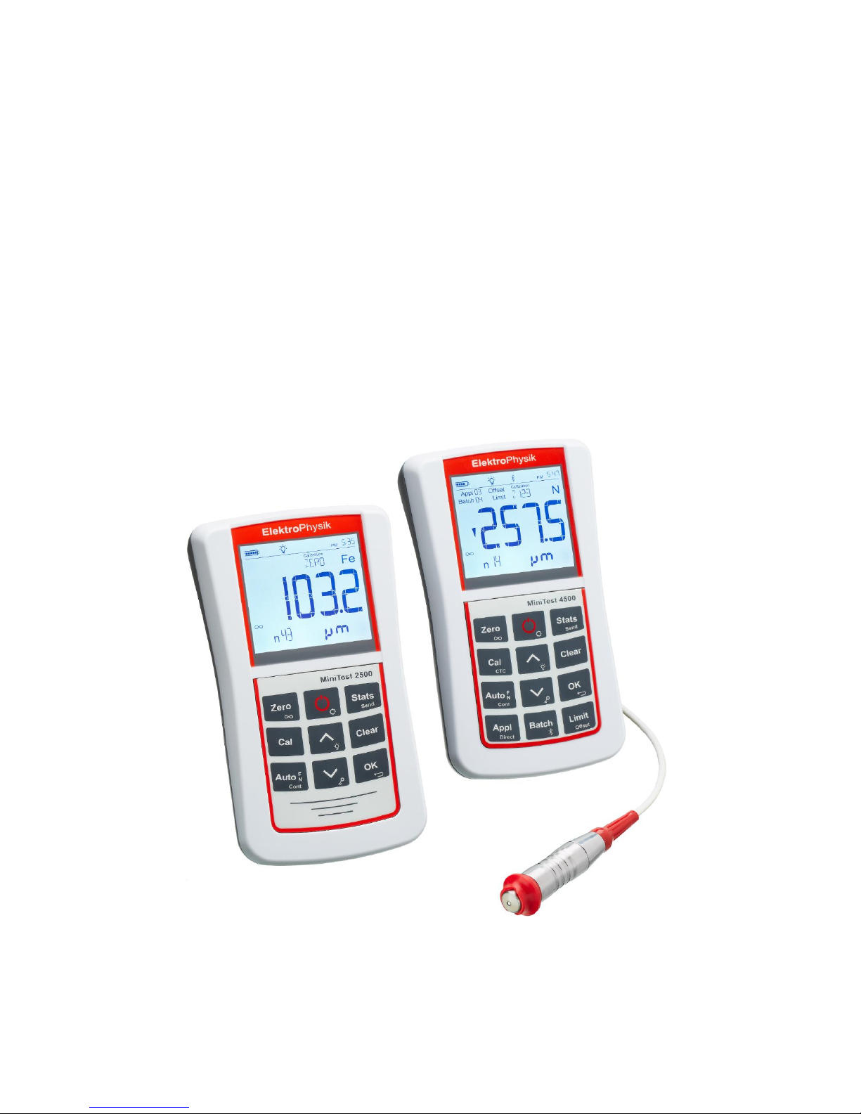
MiniTest 2500 and MiniTest 4500
Page 2

© ElektroPhysik MiniTest 2500 - MiniTest 4500 2 of 73
© ElektroPhysik
Version 1.0 14.06.2018
Gauge software Version: from 1.0.1
Sensor Software: from 1.0
Subject to technical change without notice.
ElektroPhysik
Dr. Steingroever GmbH & Co. KG
Pasteurstr. 15
50735 Cologne
Germany
Tel.: +49 221 752040
Fax.: +49 221 7520467
Internet: http://www.elektrophysik.com/
Mail:: info@elektrophysik.com
Page 3

Index
© ElektroPhysik MiniTest 2500 - MiniTest 4500 3 of 73
Index
1. Introduction ............................................................................................................................... 8
2. First steps .................................................................................................................................. 9
2.1 Inserting batteries and connecting the sensor ....................................................................... 9
2.2 Operation of the gauge ........................................................................................................ 10
3. Description of the measuring system.................................................................................... 11
3.1 Gauge ................................................................................................................................. 11
3.1.1 General ....................................................................................................................... 11
3.1.2 Front view ................................................................................................................... 11
3.1.3 Operating keys ............................................................................................................ 12
3.1.3 Interfaces .................................................................................................................... 12
3.1.4 Power supply .............................................................................................................. 12
3.1.4.1 Batteries and rechargeable batteries ........................................................................ 12
3.2 Sensors ............................................................................................................................... 13
3.2.1 Sensors of the MiniTest 1100 – 2100 - 3100 - 4100 series.......................................... 13
3.2.1.1 Adaptation of sensor types F05, F1.6, F3, F1.6/90, F2/90, F10, F20, N.08 Cr,
N02, N1.6, N1.6/90, N2/90, CN02 and FN1.6, FN1.6P, FN 1.6/90, FN2/90 ....................... 13
3.2.1.2 Adaptation of sensor types N10, N20 and N100. ................................................ 14
4. Measuring, Storage and Data Processing in DIRECT or APPL-BATCH mode .................... 15
4.1 Switch on / start-up screen .................................................................................................. 15
4.2 Structure of the APPL-BATCH system ........................................................................... 17
4.3 Switching APPL-BATCH mode on / off ................................................................ .......... 18
4.4 Displaying the number of active APPL-BATCH .............................................................. 19
4.5 Selection of an APPL memory ....................................................................................... 19
4.6 Selection of a BATCH memory ...................................................................................... 19
5. Measuring ................................................................................................................................ 20
5.1 Important Notes on Coating Thickness measurement ......................................................... 20
5.1.1 Interpretation of readings ............................................................................................ 20
5.2 Basic settings ...................................................................................................................... 20
5.3 Preparing measurement ...................................................................................................... 21
5.3.1 Calibration ................................................................................................................... 21
5.4 Taking readings ................................................................................................................... 21
5.4.1 Taking readings without using the sensor stand .......................................................... 21
5.4.2 High-precision stand ................................................................................................... 22
5.4.3 Duplex coating systems .............................................................................................. 22
5.5 Errors during measurement ................................................................................................. 22
5.6 Measurement on high temperatures using high-temp sensors ............................................ 22
Page 4

Index
© ElektroPhysik MiniTest 2500 - MiniTest 4500 4 of 73
6. Calibration ............................................................................................................................... 24
6.1 General notes on calibration ................................................................................................ 24
6.2 Calibration methods ............................................................................................................ 25
6.2.1 Factory pre-setting ...................................................................................................... 25
6.2.2.1 Zero Calibration ..................................................................................................... 25
6.2.2.2 Two-point Calibration ............................................................................................. 25
6.2.2.3 Multi-point Calibration ............................................................................................ 25
6.2.2.4 Two-point Calibration without zero ......................................................................... 26
6.2.2.5 Calibration through a coating (CTC) ...................................................................... 26
6.4.3.1 Calibration of FN-type sensors ................................................................ ............. 26
7. Calibration ............................................................................................................................... 27
7.1 Activate factory settings ................................................................................................. 27
7.2 Zero Calibration ............................................................................................................. 27
7.3 Two-point calibration (zero setting plus one calibration foil) ........................................... 28
7.3 Multi-point calibration (zero setting plus up to four calibration foils) ............................... 29
7.5 Two-point calibration using two calibration foils without zero calibration ........................ 30
7.6. Calibration Through the Coating .................................................................................... 33
7.7. Sensors N10 and N20 ................................................................................................... 34
7.7.1 Standardization (Acquisition of Infinite Value) ............................................................. 34
7.7.2 Two-point calibration (zero setting plus one calibration foil) ................................... 34
7.7.3 Elimination of dielectric interferences of the coating material ................................. 35
7.8 N100 Sensor ................................................................................................................. 35
7.8.1 Standardization (Acquisition of Infinite Value) ........................................................ 35
7.8.2 Two-point calibration (zero setting plus one calibration foil) ................................... 36
7.8.3 Elimination of dielectric interferences of the coating material ................................. 36
7.9 Sensor F20 .................................................................................................................... 37
7.10 Sensor F50 .................................................................................................................... 37
7.11 Tube sensors F1.6/90, F2/90, N1.6/90 and N2/90 ................................ ......................... 38
7.12 Chrome Coatings on Copper ......................................................................................... 38
7.13 Sensor CN02 ................................................................................................................. 38
7.14 Recalibration in an APPL memory line .............................................................................. 38
7.15 Shot-blasted and rough surfaces .................................................................................. 40
7.15.1 General .................................................................................................................. 40
7.15.2 Method A (roughness Rz > 20µm) ......................................................................... 40
7.15.3 Method B (roughness Rz < 20µm) ......................................................................... 40
7.15.3 Method C Calibration with two calibration foils of different thickness ...................... 40
8. Data Management ................................................................................................................... 41
8.1 Batches ............................................................................................................................... 41
Page 5

Index
© ElektroPhysik MiniTest 2500 - MiniTest 4500 5 of 73
8.1.1 General ....................................................................................................................... 41
8.2 Offset .................................................................................................................................. 41
8.3 Block size ............................................................................................................................ 41
8.4 Upper limit / Lower limit ................................................................................................. 41
8.5 Single values / Continuous measurement mode ............................................................ 42
8.6 Measuring with statistics ..................................................................................................... 42
8.7 Taking a series of measurement with statistical calculation ........................................... 43
8.8 Deleting outliers or erratic readings ............................................................................... 43
8.9 Storage capacity overflow .............................................................................................. 44
8.10 Display or print-out of a series of measurements ............................................................... 44
8.10.1 Single value statistics ............................................................................................. 44
8.10.2 Block value statistics .................................................................................................. 45
9. Deletion.................................................................................................................................... 46
9.1 Deleting the last reading ................................................................................................ 46
9.2 Deleting statistical values ................................ .............................................................. 46
9.4 Deleting a series of measurements including limits and statistics within an APPL-BATCH
memory ..................................................................................................................................... 46
9.5 Deleting limit values within an APPL-BATCH memory ......................................................... 46
9.6 Deleting all series of measurements incl. statistics, limits and calibration values of an
APPL memory ........................................................................................................................... 47
9.7 Total Reset .................................................................................................................... 47
10. Data output and transfer ....................................................................................................... 48
10.1 Printing data ...................................................................................................................... 48
10.2 Data transfer to PC (terminal program) .............................................................................. 48
10.3 Read out data via a PC ..................................................................................................... 49
11. Further functions .................................................................................................................. 50
11.1 Initialization ....................................................................................................................... 50
Initial functions and settings ................................................................................................. 50
11.1.1 Total Reset ........................................................................................................ 50
11.1.2 LCD Segment Test ............................................................................................ 50
11.2 Gauge configuration .......................................................................................................... 50
11.2.1 Blockgröße ................................................................................................................ 50
11.2.2 Display illumination ................................ ................................................................ 51
11.2.3 Keypad illumination ................................................................................................ 51
11.2.4 Acoustic signal ....................................................................................................... 51
11.2.5 Time and date stamp ............................................................................................. 51
11.2.6 Time and date ........................................................................................................ 51
11.2.7 Measuring unit: ‘metrical’ - Inch’ (imperial) ............................................................. 52
11.2.8 Automatic data transfer in continuous mode .......................................................... 52
Page 6

Index
© ElektroPhysik MiniTest 2500 - MiniTest 4500 6 of 73
11.2.9 Timestamp ............................................................................................................. 52
11.2.10 Setting of display colours for measurements ...................................................... 52
11.2.11 Setting of display colours for readings above preset limits ................................. 53
11.2.12 Setting of display colours for readings below preset limits .................................. 53
11.2.13 Optional alarm output – Setting of signal length of the measuring value............. 53
11.2.14 Optional alarm output – Setting of signal length for readings above limits .......... 53
11.2.15 Optional alarm output – Setting of signal length for readings below limits .......... 53
11.2.16 Configuration of the optional foot switch ............................................................. 53
11.2.17 Pairing of a BLUETOOTH printer ....................................................................... 53
11.2.19 Format of logged measuring values ................................................................... 54
11.2.20 SENSOR INIT .................................................................................................... 54
11.2.21 „POWER SUPPLY“ Setting ................................................................................ 54
11.2.22 „POWER OFF“ Switch off time ........................................................................... 55
11.2.23 SYSINFO ........................................................................................................... 55
11.2.24 Table of basic settings for MiniTest 4500 ................................................................ 56
11.2.25 Table of basic settings for MiniTest 2500 ................................................................ 57
12. Accessories ........................................................................................................................... 58
12.1 General ............................................................................................................................. 58
13. Care and maintenance .......................................................................................................... 59
13.1 Care ................................ ................................................................................................ .. 59
13.1.1 Using NiMH rechargeable batteries ........................................................................... 59
13.2 Maintenance...................................................................................................................... 60
14. Technical data ....................................................................................................................... 61
14.1 Gauge specification ........................................................................................................... 61
14.2 Sensor specifications ................................................................................................ ........ 62
14.3 Standard supply ................................................................................................................ 65
14.3.3 Coating thickness gauge MiniTest 2500/ 4500 with interchangeable sensor ............. 65
14.3.4 Interchangeable sensors for MiniTest 2500/4500 ................................ ...................... 65
14.4 Accessories ....................................................................................................................... 66
15. Annexe ................................................................................................................................... 67
15.1 Error messages and trouble shooting ................................................................................ 67
15.2 Statistical terms ................................................................................................................. 68
15.3 Safety notes ................................ ................................................................ ...................... 69
15.4 Declaration of conformity according to EU directive ........................................................... 70
15.5 Return of used equipment ................................................................................................. 70
15.6 Service-Adressen ................................ ................................................................ .............. 71
16. Change history ...................................................................................................................... 72
17. Index ...................................................................................................................................... 73
Page 7

Index
© ElektroPhysik MiniTest 2500 - MiniTest 4500 7 of 73
Page 8

1. Introduction
© ElektroPhysik MiniTest 2500 - MiniTest 4500 8 of 73
1. Introduction
The new coating thickness gauges MiniTest 2500 and MiniTest 4500 combine high precision modern
measuring technique and a classic handling concept.
Coating thickness gauges MiniTest 2500 and MiniTest 4500 measure non-destructively according
to the magnetic induction or the eddy current principle depending on the sensor type connected to
the gauge. The gauges comply with the following standards:
DIN EN ISO 1461
DIN EN ISO 2064 DIN EN ISO 2178
DIN EN ISO 2360
DIN EN ISO 2808
DIN EN ISO 19840
ASTM B244
ASTM B499
ASTM D7091
ASTM E376-03
AS 3894.3-2002
SS 18 41 60
SSPC-PA 2
The portable gauge is used for quick and precise non-destructive coating thickness measurement in
the field of industrial corrosion protection and is used by manufacturers and end users of corrosion
protected products, by authorities and inspectors,in electroplating and paint shops as well as in
chemical industry, automotive production, ship building, aviation and tool and machine engineering.
MiniTest coating thickness gauges are equally qualified for use in a laboratory as well as in rough
industrial environments or construction sites thanks to their particularly rugged housing designed in
protection class IP65.
A broad selection of measuring sensors is available for the MiniTest 2500/4500 line of coating
thickness gauges allowing to handle standard applications as well as more complex measuring tasks
as for example measurement in tubes or thick coatings up to 100mm coating thickness.
The intelligent MiniTest-sensors also cope with sophisticated applications such as measurement of
objects with unusual geometry or coatings with special material properties. This wide range of
applications is possible through memorization of corresponding key data within the sensor which are
automatically taken into account at each measurement
The scope of application is determined by the sensor connected to the gauge:
F-type sensors work according to the principle of magnetic induction and can measure non-
magnetic coatings such as paint, enamel, rubber, aluminum, chrome, copper, zinc etc applied on
iron and steel (including steel alloys and hardened magnetic steels).
N-type sensors work according to the eddy current principle and measure insulating coatings
such as paint, anodizing, ceramics etc. applied on all non-ferrous metals (for example aluminum,
copper, zinc die cast, brass etc.) including austenitic steels.
FN-type sensors combine both principles and identify the substrate underneath the coating thus
automatically switching to the correct measuring principle to measure on base material steel or
non-ferrous metal.
Modern data administration allows simple access to the internal data memory with maximum
storage capacity of up to 2 million measuring values. MiniTest 4500 features a data memory with
‘APPL-BATCH mode’ allowing measurement and storage of readings in a user definable memory.
A total of up to 2,000,000 readings and more than 9,800 batches can be evaluated according to
different statistical principles. The option limit setting (LIMIT) offers to determine Cp and Cpk
values.
Both models feature a USB interface to connect to notebooks and PCs. MiniTest 4500 additionally
offers a Bluetooth interface for wireless data transfer to mobile devices like Smartphones and
printers directly on site..
Page 9
2. First steps
© ElektroPhysik MiniTest 2500 - MiniTest 4500 9 of 73
2. First steps
This section addresses first time users of a MiniTest coating thickness gauge introducing the basic
functions of the gauge and demonstrating how to take readings.
2.1 Inserting batteries and connecting the sensor
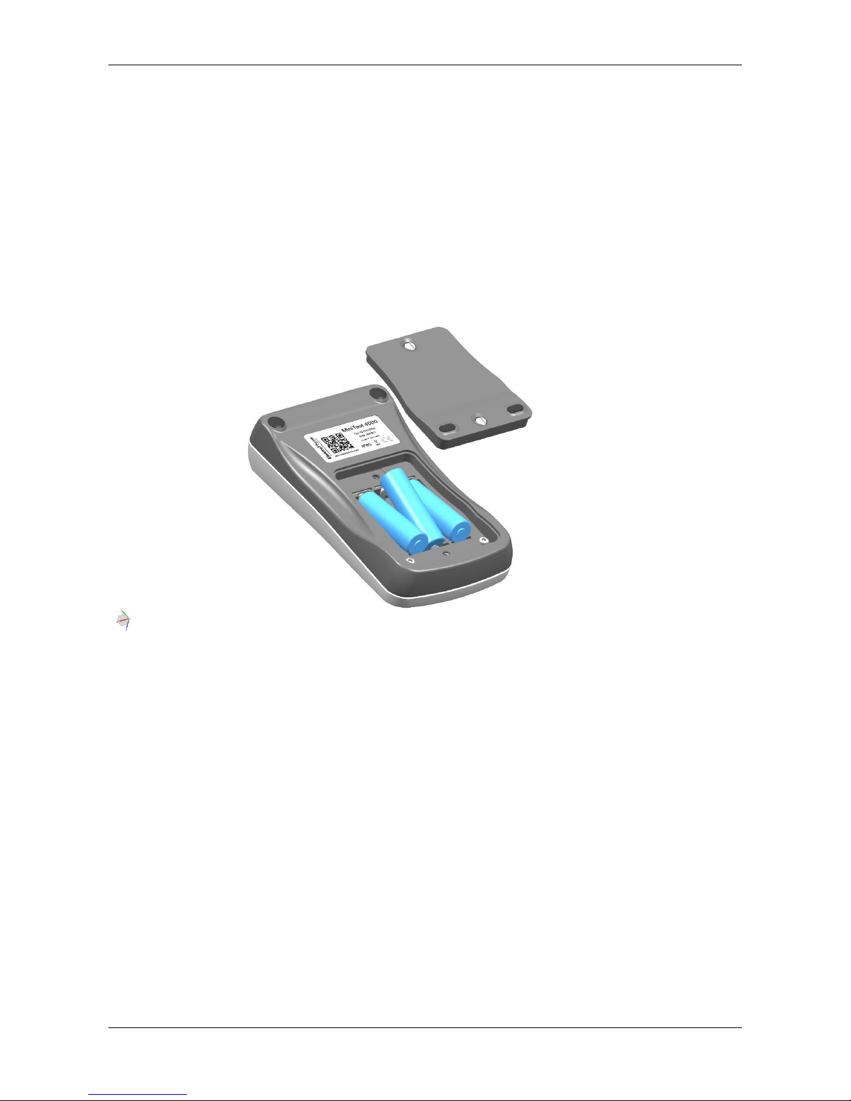
a) Withdraw the gauge and the batteries from the storage case.
b) Untighten the screws of the battery compartment on the back of the gauge using for example a
coin and open the battery compartment.
c) Insert the batteries from the supply schedule observing correct polarity (see illustration).
d) Close the battery compartment and fix the lid with the screws.
Page 10
2. First steps
© ElektroPhysik MiniTest 2500 - MiniTest 4500 10 of 73
2.2 Operation of the gauge
Press the red ON-OFF key to switch the gauge on.
a) The gauge is now switched to measuring mode (see illustration.) and is ready to measure. The
display shows the measurement screen without measuring value.
b) Upon initial operation the measuring series is set to „Direct Mode“ and factory calibration is
preset (For more detailed information on „Calibration” refer to chapter 6).
c) The factory pre-setting is recommended for quick and easy measurement and if a medium
measuring accuracy is sufficient. For a detailed description of different calibration methods refer
to chapter 6.2.
d) To take readings, place the sensor in right angle onto the measuring object. The coating
thickness will be displayed on the screen after a short while (less than a second). Remove sensor
and take next reading.
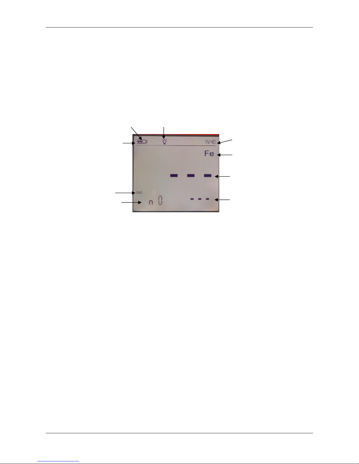
Status bar
Display Illumination
Battery-
level
Activated measuring
principle: Fe
Time
Number of
readings
Measuring
unit
current
reading
Sensor is lifted
from surface
Page 11

3. Description of the measuring system
© ElektroPhysik MiniTest 2500 - MiniTest 4500 11 of 73
3. Description of the measuring system
3.1 Gauge
3.1.1 General
A large optionally backlit display allows easy reading of measuring values and statistical data.
The colour of the backlit display is user definable thus offering for example quick marking of a
reading within limits in green and outside limits in red.
The housing is made of an impact-proof and scratch-resisting material and conforms to protection
class IP 65.
3.1.2 Front view
1. USB-Interface
2. Battery charge level
3. Note: Selected APPL-Batch group
4. Offset note: Offset is activate
5. Limit note: Limits are active
6. Note: Reading is within, above or below preset limits
7. Note: Statistical value (here: Mean value)
8. Note: Readings are blocked
9. Note: Number of readings
10. Zero key to calibrate zero without calibration standard/
Double assignment Recording of infinite value when
working with sensor types N10, N20, N100
11. Calibration key for calibration with precision standards /
Double assignment Calibration through a coating (CTC)
12. Key to select measuring principle Ferrous, Non-Ferrous
or Auto FN when using FN sensors /
Double assignment Switch to continuous mode
13. Activation key for DIRECT- or APPL-BATCH Mode
14. Key to access a subgroup (BATCH) within an
APPLICATION /
Double assignment Activate / Deactivate Bluetooth
Interface
15. Key to enter limit values /
Double assignment Key to enter an Offsets
16. Arrow keys for navigation in settings, e.g. calibration and
limit values, key lock
17. Key to confirm an action /
Double assignment ESCAPE or QUIT function
18. Arrow keys for navigation in settings, e.g. calibration and
limit values, key lock
19. Delete key
20. ON/OFF switch and initial functions
21. Key to visualize statistical values and transfer measuring
and statistical values to printer, PC or APP Miniview
22. Measuring unit: Automatically selected according to
preselection of the sensor connected: µm, mm or mils,
inches
23. Current reading
24. Active calibration method is displayed; here ZERO
25. Active measuring principle N-Fe (when measuring on
non-ferrous metal) or FERROUS (when measuring on
steel
26. Display of time
27. Sensor plug
28. Note: Bluetooth active/paired
29. Optional socket: 1. To connect an external trigger (e.g.
footswitch), 2. To trigger a signal confirming the
measuring value (optical or acoustical), RS 232 Interface
30. Note: PC connection via USB active
31. Note: Keypad locked
2
3
4
5
7
8
22 6 9
15
14
16
17
18
19
21
20
10
11
12
13
23
24
25
1
26
27
29
28
30
31
Page 12

3. Description of the measuring system
© ElektroPhysik MiniTest 2500 - MiniTest 4500 12 of 73
3.1.3 Operating keys
MiniTest 2500 and MiniTest 4500 are equipped with a generous keypad. One key pressure is
sufficient to access functions like calibration, limit setting, and display of statistics.
The ON-OFF-key serves to switch the gauge on or off. Switching the gauge on by simultaneously
pressing the ON-OFF key and the keys + Clear, a total reset is carried out and the gauge returns
factory settings (For more detailed information on initial functions refer to section 11.1).
All keys have a double assignment. Simple pressure of a key will access the functions shown in
major writing like ‘Zero’ and ‘Stats’ (Statistics). Functions shown in minor grey writing like ‘ ’ and
‘Send’ are accessed by keeping the key depressed for approximately 0.5 seconds.
- ‘OK’ confirms settings and selects menu points.
- ‘ ’ quits an action or a menu.
- ‘ ’ or ‘ ’ modify settings and navigate within initial functions.
- ‘Clear’ deletes the last reading, the statistics, an application ‘Appl’, a series of measurements
‘Batch’ or limit and offset values.
- ‘ ’ opens the table of initial functions
- ‘ ’ activates and deactivates display and keypad illumination
- ‘ ’ locks the keypad with a password
- ‘ ’ activates and deactivates the Bluetooth Interface (only MiniTest 4500).
3.1.3 Interfaces
The model MiniTest 4500 is equipped with a USB and Bluetooth interface. MiniTest 2500 is only
equipped with a USB interface.
3.1.4 Power supply
3.1.4.1 Batteries and rechargeable batteries
Coating thickness gauges MiniTest 2500 and 4500 are powered by three alkaline-manganesebatteries 1.5V, type AA / LR6 (included in standard supply); alternatively, the gauge can be operated
on rechargeable NiMH batteries type AA / HR6. Please use only the battery types recommended
by ElektroPhysik (see section 13.1 Accessories).
When working with rechargeable batteries, the settings of the gauge must be adapted to
rechargeable batteries (section 13.1.1). An external charger is required to recharge the batteries
(Accessories).
For more detailed information on the use of batteries and rechargeable batteries, refer to section
13.1.1.
Note:
- Remove batteries or rechargeable batteries from the instrument if not in use for extended
periods.
- The battery symbol indicates 5 different battery states. l.
- When reaching the lowest battery state, the battery level symbol will start to flash. In this
state, voltage is insufficient for powering the display backlight and keypad illumination. The
symbol is no longer displayed.
Page 13

3. Description of the measuring system
© ElektroPhysik MiniTest 2500 - MiniTest 4500 13 of 73
- If batteries are completely discharged, the messages „E06“ and „Low Batt“ appear and the
gauge switches off.
- Insert fresh batteries within one minute immediately after removing the used ones. If you
wait for longer than one minute, time settings may be lost. However, readings and
calibration values will remain in memory.
- For field use, replacement batteries should always be at hand
- Erratic readings due to low battery do not occur as the gauge switches off automatically or
does not switch on at all if batteries are too low.
- Used or defective batteries or rechargeable batteries may contain hazardous substances
and must be disposed of according to the legal provisions of your country.
3.2 Sensors
Select a sensor suitable for your measuring task, plug to the gauge and screw on.
Important: Whenever a sensor is connected or removed, the gauge must be switched off.
All sensor systems (except sensor type CN02 and customized designs) are spring-mounted in the
handling sleeve. This construction ensures stable positioning of the sensor with a constant contact
pressure. The V-groove at the top of the handling sleeve allows reliable measurement on objects
of cylindrical shape.
Hold the sensor at the handling sleeve and place on the object to be measured.
Note: Sensors are equipped with a hard, wear-proof sensor pole. However, sliding sensors across
rough and hard surfaces, for example shot blasted surfaces, should be avoided.
3.2.1 Sensors of the MiniTest 1100 – 2100 - 3100 - 4100 series
All sensors of the predecessor series are compatible with coating thickness gauges MiniTest 2500
and MiniTest 4500. However, it is required to perform a one-time adaptation of the sensor to the
measurement electronics.
3.2.1.1 Adaptation of sensor types F05, F1.6, F3, F1.6/90, F2/90, F10, F20, N.08 Cr, N02, N1.6,
N1.6/90, N2/90, CN02 and FN1.6, FN1.6P, FN 1.6/90, FN2/90
Upon initial connection of the sensor to the gauge, the MiniTest 2500 or 4500 will display “INF”
flashing as well as “SET” and “SENSOR IN AIR” when switched on.
Hold the sensor in a sufficient distance to any metal and press the OK key.
‘INF’ and ‘WAIT’ will continue to flash on the display and a counter will count down from 30 to 0.
Keep the sensor away from any metal until the counter has reached ‘0’.
Once the ‘INF’ adaptation is completed, ‘ZERO”, ‘NFe” and ‘ALUMINIUM-PLATE’ will flash on the
display when an N-type or FN-type sensor is connected to the gauge.
Place the sensor on the aluminum zero standard.
‘ZERO’ and ‘ALUMINIUM-PLATE’ will continue to flash on the display and a counter will count
down from 30 to 0. Do not remove the sensor from the standard until the counter has counted
down to ‘0’.
Once the aforesaid adaptation is completed, ‘ZERO”, ‘Fe” and ‘STEEL-PLATE’ will flash on the
display when an F-type or FN-type sensor is connected to the.
Place the sensor on the steel zero standard.
Page 14

3. Description of the measuring system
© ElektroPhysik MiniTest 2500 - MiniTest 4500 14 of 73
‘ZERO’ and ‘STEEL-PLATE’ will continue to flash on the display and a counter will count down
from 30 to 0. Do not remove the sensor from the standard until the counter has counted down to
‘0’.
‘SAVE’ and ‘OK’ will flash on the display.
Press ‘OK’ in order to complete the adaptation of the sensor. Gauge and sensor are now ready to
measure.
Adaptation of a sensor to the series MiniTest 2500 / 4500 does not affect the use of the same
sensor with a gauge from the series MiniTest 1100 / 2100 / 3100 / 4100.
The adaptation procedure can be repeated at any time in point 20 of the initial settings.
Note: Sensor type F 20 requires a multi-point calibration according to section 7.4 in order to
adhere to the tolerances. Sensor type F 50 is only supported by the MiniTest 2500 / 4500 series
beginning from software version 1.1.
3.2.1.2 Adaptation of sensor types N10, N20 and N100.
To adapt the sensor to the gauge, the zero standard and the three precision standards from the
calibration set supplied with the sensor is required.
When a sensor from the MiniTest 1100-4100 series is connected to a MiniTest 2500 or 4500 for
the first time, the gauge will display ‘INF”, ‘SET’ and ‘ON COATING WITHOUT SUBSTRATE‘ after
being switched on.
Place the sensor on the three precision standards stacked on top of each other and hold the
sensor and the precision standards in the air keeping a sufficient distance to any metal objects or
place the three standards on a polystyrene plate. Press the OK key. This procedure eliminates
dielectric influences oft he coating material as described in section 7.7.3.
‘INF’ and ‘WAIT’ will continue to flash on the display and a counter will count down from 30 to 0.
Keep the sensor away from any metal until the counter has reached ‘0’.
Once the ‘INF’ adaptation is completed, ‘ZERO”, ‘NFe” and ‘ALUMINIUM-PLATE’ will flash on the
display when an N-type or FN-type sensor is connected to the gauge.
Place the sensor on the aluminum zero standard.
‘ZERO’ and ‘ALUMINIUM-PLATE’ will continue to flash on the display and a counter will count
down from 30 to 0. Do not remove the sensor from the standard until the counter has counted
down to ‘0’.
‘SAVE’ and ‘OK’ will flash on the display.
Press ‘OK’ in order to complete the adaptation of the sensor. Gauge and sensor are now ready to
measure.
Adaptation of a sensor to the series MiniTest 2500 / 4500 does not affect the use of the same
sensor with a gauge from the series MiniTest 1100 / 2100 / 3100 / 4100.
The adaptation procedure can be repeated at any time in point 20 of the initial settings.
Hold the sensor in a distance to any metal and press ‘OK’.
Precision standards
Polystyrene plate
Page 15
4. Measuring, Storage and Data Processing in DIRECT or APPL-BATCH mode
© ElektroPhysik MiniTest 2500 - MiniTest 4500 15 of 73
4. Measuring, Storage and Data Processing in DIRECT or
APPL-BATCH mode
The following section describes:
the DIRECT mode
the APPL-BATCH mode
the structure of APPL-BATCH memory system
How to change from DIRECTto APPL-BATCH mode
How to select a scertain memory in APPL-BATCH mode
How to enter calibration values and limits
Special features of the APPL-BATCH memory system.
APPL = Application memory
BATCH = Memory for series of measurement
4.1 Switch on / start-up screen
Being switched on the unit will display the measurement mode of the last active series of
measurements („Batch“).
The model MiniTest 4500 offers two different working modes: ‘DIRECT mode’ and ‘APPL-
BATCH mode’.
‘DIRECT mode’ is intended for quick occasional readings. Readings as well as the 6
statistical values (8 if limits have been set) can be shown on the display and printed by
pressing STATS’. The statistical analysis function can evaluate up to 9,999 readings.
In ‘APPL-BATCH mode’ a maximum of 10,000 single readings and approx. 500 separate
series of measurements can be stored in data memory individually. Single readings,
statistical values and the related histogram can be printed directly or at a later point.
Important note:
Working in APPL-BATCH mode (e. g. calibrating, measuring setting of limits etc.) is only possible,
when the display shows „APPL BATCH“. Otherwise, activate the APPL-BATCH memory using the
keys APPL and BATCH. Also refer to Section 3.4 and 3.5.
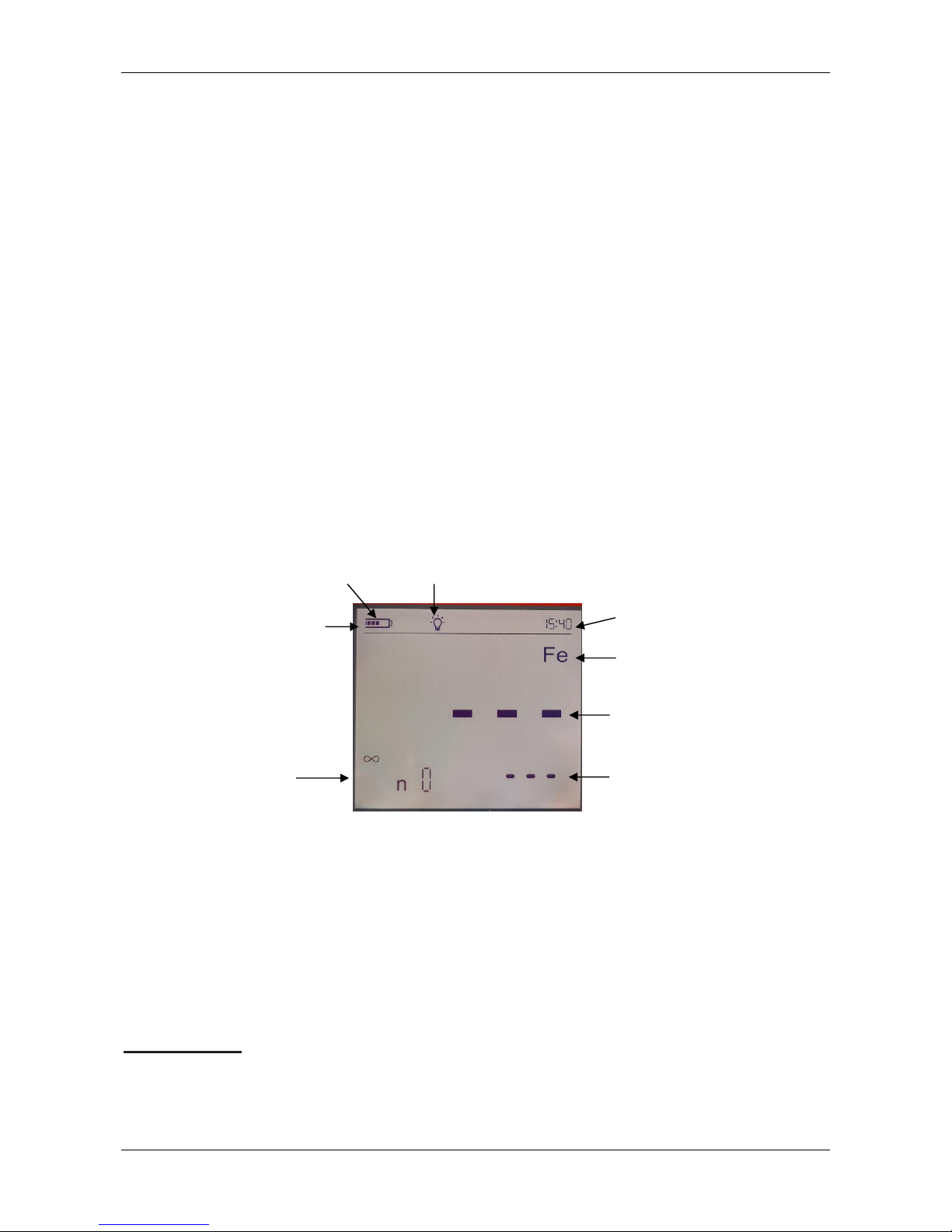
Status line
Display Illumination
Batterylevel
Active measuring
principle: Fe
Time
Number of
readings
Measuring
unit
Current
reading
Page 16

4. Measuring, Storage and Data Processing in DIRECT or APPL-BATCH mode
© ElektroPhysik MiniTest 2500 - MiniTest 4500 16 of 73
Status after Switch on
Press ON key while holding the probe in the air. The gauge automatically resumes the mode
selected previously (either ‘DIRECT-’ or ‘APPL-BATCH’).
If start-up proceeds in ‘APPL-BATCH mode’, the gauge will select the ‘APPL-BATCH’ memory
previously selected and the last ready (if available) will be displayed.
Calibration values and statistics are stored in memory.
Measurement can start directly in ‘DIRECT mode’ or be continued in ‘APPL-BATCH’ mode
provided the gauge works with a valid calibration.
If all data have been deleted, only the measuring unit, e.g. < µm > along with the measuring mode
FERROUS or NONFERROUS will be shown depending on the sensor connected to the gauge.
Note:
If you switch from ‘DIRECT’ mode to ‘APPL-BATCH’ mode, all statistical data will be kept in
memory.
The statistical data will not be stored if you change the probe.
When pressing the APPL-BATCH key, the pair of numbers of the last active APPL-BATCH
memory will be shown on the display.
The gauges switches off automatically according to the selected switch-off-time after the last
measurement (see also section 11.1 initial settings).
Page 17
4. Measuring, Storage and Data Processing in DIRECT or APPL-BATCH mode
© ElektroPhysik MiniTest 2500 - MiniTest 4500 17 of 73
4.2 Structure of the APPL-BATCH system
MiniTest 2500 and MiniTest 4500 generally group reading in series of measurements in one
memory batch. MiniTest 2500 features one fixed memory (DIRECT) whereas MiniTest 4500
features one DIRECT memory and 99 application memories (APPL) combined with memories for
series of measurements (BATCH).
New readings are always added to the active memory and stored. The gauge will preserve the
active memory when switched off and automatically resume this memory when switched on again
not requiring any further settings. The following actions are possible:
- Continue to measure in active memory
- Set up a new series of measurement (BATCH) within an application memory (APPL)
- Set up of a new application memory (APPL) with corresponding series of measurement
(BATCH)
- Selection of an existing series of measurement (BATCH) within an application memory
(APPL)
- Selection of an existing application memory (APPL) with corresponding series of
measurement (BATCH))
Perform one of the above mentioned actions in order to specify the active series of measurement
(BATCH) for measurements hereinafter.
The application memories (APPL) with their corresponding batch memories (BATCH) allow to
store calibration settings for different applications in an application memory (APPL). The batch
memory (BATCH) stores single readings of a series of measurement along with their statistical
analysis (see illustration: APPL-BATCH memory).
BATCH memory columns
APPL
(application) memory
lines
1 2 3
...
97
98
99
1
1 2 3 97
98
99 2 1 2 3 97
98
3 1 2 3 97
98
.
.
.
Page 18

4. Measuring, Storage and Data Processing in DIRECT or APPL-BATCH mode
© ElektroPhysik MiniTest 2500 - MiniTest 4500 18 of 73
97
1 1 1 97
98
98
1 1 1 97
98
99
1 1 1 97
98
99
Illustration: APPL-BATCH memory
With MiniTest 4500 99 application memories (APPL-memory lines) – subdivided in 99 BATCH-
memory columns each, i.e. 9,801 memories in total, are available.
Several million readings can be logged to the memory.
APPL memory line
(for saving calibration values only)
Each of the 99 application memory lines can be allotted a calibration and an OFFSET setting for
one probe. A selection of calibrations are thus instantly available for different tasks, e.g. for
measuring coating thickness on flat or curved surfaces or for taking measurements using a range
of probe types. Once a calibration has been entered into an APPL memory line it remains there
and can be activated at any time simply by entering the corresponding APPL number. After this,
readings can start immediately within a selected group (BATCH) of particular application memory
BATCH-(Group) Memory
(for storing limits and readings)
Each of the application memories (APPL memory lines) is subdivided into BATCH memories. Each
BATCH memory can store a series of readings using one calibration and also evaluate them in
statistical form. In addition, a set of two tolerance limits (LO and HI) can be stored in each BATCH
memory. The BATCH subdivisions provide for individual assessment of the coatings of a number
of product samples measured with one probe and based on the same calibration.
4.3 Switching APPL-BATCH mode on / off
When the gauge is switched on it will resume the previously selected mode, i.e. either APPL-
BATCH or DIRECT mode.
In order to switch from DIRECT to APPL-BATCH mode, press ‘APPL’. The last APPL-BATCH
number will appear, e.g. < 2 : 1 >.
Either continue taking readings in this APPL-BATCH memory or select a different memory (see
section 4.5). Confirm your choice by pressing ‘APPL’ again. Readings can be taken as soon as
“APPL-BATCH” appears on display.
Page 19

4. Measuring, Storage and Data Processing in DIRECT or APPL-BATCH mode
© ElektroPhysik MiniTest 2500 - MiniTest 4500 19 of 73
To switch from APPL-BATCH mode to DIRECT mode, press and hold the APPL key while the
gauge is switched on. DIRECT mode is activated and the gauge is ready to measure.
4.4 Displaying the number of active APPL-BATCH
If the gauge is switched on and is already functioning in APPL-BATCH mode, a reading will
normally be displayed.
Press either APPL or BATCH to display the two-number memory in current use, e.g.<2 : 1>. Press
the same key again to confirm your choice. Readings can be taken as soon as APPL-BATCH
appears on the display.
4.5 Selection of an APPL memory
1. Press the APPL key in order to display the two-number designation of the active APPL-BATCH
memory. Use the arrow keys to select a new APPL memory.
2. If you hold down the key you can quickly scroll through the memory showing a running display
of numbers already occupied until a free APPL address is found. The number of this memory
will then appear on screen, e.g. < 5 : 1>. Free memories can be distinguished by a flashing
APPL number.
Note:
An APPL memory can be activated directly by connecting the sensor that served to create the
APPL memory originally. If another sensor even of the same sensor type is connected, the
message “LOC“ will be displayed along with sensor type and serial number.
This also happens if the probe which has been used for APPL-memory creation has been
repaired.
To delete or select APPL-memories please refer to section 9.6
3. The calibration valid for your selected APPLmemory is shown on display, e.g. one-point or
twopoint calibration. If the standard calibration is valid, there will be no indication on the
display.
Either maintain the currently valid calibration or recalibrate according to one of the methods
described in section 7.1 to 7.13.
4. All following readings will be stored in the selected APPL-BATCH memory.
4.6 Selection of a BATCH memory
1. Select an APPL memory line if this has not been done.
2. Press BATCH. The number of the previously selected number will now appear, e.g. <3 : 2>.
If, for example, APPL memory line number 3 has not yet been used, the gauge automatically
selects the first BATCH memory, e.g. <3 : 1 >. A free BATCH is indicated by flashing numbers
on the display.
3. If required, use the arrow keys to select a new BATCH no. Keep the key pressed down for
quickly scrolling through the memory until a free BATCH number is found. The number will
then be displayed, e.g. <3 : 8>. Press BATCH to confirm.
Page 20

5. Measuring
© ElektroPhysik MiniTest 2500 - MiniTest 4500 20 of 73
5. Measuring
5.1 Important Notes on Coating Thickness measurement
Make sure the operator has been properly instructed regarding the use of coating thickness
gauges and has basic knowledge of the specific requirements for measurement of the application.
The operator should have basic knowledge of the following:
Appropriate selection of a measuring device suitable for his application
Fundamentals on the electro-magnetic measuring principle
Influences through magnetic fields and the surrounding fields
Influence through the surface properties of the object to be tested (roughness, shape and
build-ups on the surface)
Statistical evaluation of measuring series
5.1.1 Interpretation of readings
The information obtained from the coating thickness measurement only refers to those parts of the
test object that have been covered by the sensor. For that reason, conclusions may not be drawn
on parts of the measuring object that have not been covered by the sensor during measurement.
In general, such conclusions are only admissible if comprehensive experience and approved
methods of statistical data acquisition are available.
5.2 Basic settings
Before taking readings, it is necessary to adjust a few settings:
Fix the data format for data storage before the first use of the gauge.
Either comma or point are available. This setting is important for later transfer of data to a
spreadsheet calculation for example Microsoft Excel (see section 10.2)
If required or necessary, the following settings can also be performed at initial set-up:
Definition of block statistics (see section 8.3)
Limit setting (see section 8.4)
Offset setting (see section 8.2)
All readings will be stored to the active APPL-BATCH memory.
Note:
Limits can still be set after readings have been taken.
Page 21

5. Measuring
© ElektroPhysik MiniTest 2500 - MiniTest 4500 21 of 73
5.3 Preparing measurement
5.3.1 Calibration
According to your setting of task, you may use different calibration methods. Measuring accuracy
depends on the selected calibration method. .
The following calibration methods are available. (see section 6.2):
- Factory presetting
- Zero point calibration
- Two-point calibration
- Multi-point calibration
- Calibration through a coating when the base material is not accessible (CTC)
5.4 Taking readings
5.4.1 Taking readings without using the sensor stand
All sensor systems are spring-mounted to ensure a safe contact pressure on the measuring object
without tilting. The V-groove of the sensor ensures correct positioning of the sensor on cylindrical
objects.
To take readings, place the external sensor onto the object to be measured. As soon as the sensor
has been placed onto the object, a reading will be displayed and will be registered for statistics
when working in “single value” mode. Lift the sensor briefly from the surface and take the next
reading.
In „continuous mode”, readings are displayed continuously as long as the sensor scans the
surface. To store the single reading being displayed into the statistics, press the „OK” key.
Note that grinding movements on the measuring object will affect the sensor pole (small pin in the
center of the sensor end surface touching the measuring object) and lead to abrasion which should
be prevented in order to maintain the high precision of the gauge.
Page 22

5. Measuring
© ElektroPhysik MiniTest 2500 - MiniTest 4500 22 of 73
5.4.2 High-precision stand
In order to take readings on small objects and small geometries, it is recommended to use the
external sensor in connection with the high-precision stand.
Measurement with standard sensor
5.4.3 Duplex coating systems
To add additional corrosion protection to a product or for design reasons, it is common practice to
apply a zinc coating to a steel product before painting. For measurement of zinced steel with
additional surface finish, please use the dual sensor FN 1.6. This sensor type allows to determine
the total coating thickness working in „Ferrous” mode and then the thickness of the paint coating on
the zinc substrate working in „Non-Ferrous”mode. The thickness of the zinc coating is calculated by
subtracting the paint thickness from the total thickness value.
Verify the zero value in non-ferrous setting with a zinc-coated but not yet painted sample. Starting
from a 50µm zinc thickness, the zero value is sufficiently good so that you can measure your duplex
coating as described aboven.
5.5 Errors during measurement
After the sensor has been calibrated, you can proceed on taking readings in the measuring mode.
Readings will be correct as long as the sensor specifications will be observed. Please refer also to
section 6.1 Calibration “General remarks“ and Section 13 “Technical specifications“.
5.6 Measurement on high temperatures using high-temp sensors
The measuring system MiniTest 2500 / MiniTest 4500 (gauge + sensor) is designed for a
maximum operating temperature of 50°C / 122°F for the gauge and 70°C / 158°F, at short periods
120 °C / 248°F for the sensor. Whilst the current operating temperature of the gauge depends on
the ambient temperature of the air, the current operating temperature of the sensor is also
influenced by the surface temperature of the object to be measured. This is due to the heat transfer
taking place when the sensors comes into contact with the object to be measured.
Measurements on objects with surface temperatures higher than the specified sensor operating
temperature are permissible with the special high-temperature sensors
80-0A1-1202 - F2 HT up to 250°C / 482°F and
80-0A1-1302 - F2 HT up to 350°C / 662°F
under the following conditions.
1. When taking readings, a measuring signal will sound approx. 1 second after placing the
sensor onto the object to be measured in order to confirm acquisition of the reading. Make
sure to lift the sensor immediately after the bleep sounds. This is to keep the heat transfer
from the object to the sensor as low as possible. Do not keep the senor in contact with the
measuring object for longer than one second.
2. Note that between two subsequent measurements on hot surfaces, a recovery time is
required to cool down the sensor. Please refer to the table below for the temperature
Page 23

5. Measuring
© ElektroPhysik MiniTest 2500 - MiniTest 4500 23 of 73
depending recovery times. If the below recovery times are respected, a virtually unlimited
number of subsequent measurements can be taken.
3. During a measurement pause, make sure not to place the sensor on hot surfaces to prevent
heating up. Keep the sensor away from hot measuring objects to prevent heating up through
heat radiation.
Sensor recovery times in high-temp operation
Temperature / °C
100
150
200
250
300
350
Temperature / °F
212
302
392
482
572
662
Recovery time / s
1
2.5 6 12
20
30
Page 24

6. Calibration
© ElektroPhysik MiniTest 2500 - MiniTest 4500 24 of 73
6. Calibration
6.1 General notes on calibration
The MiniTest 2500/4500 series offers a number of calibration methods to meet the individual
requirements of various applications, procedures and industrial standards.. When a batch is being
created you can select a suitable calibration method for this batch. The calibration can be carried
out immediately after you have created a batch or at a later time in measuring mode using the
„CAL” key. The calibration method can be changed as long as no readings are stored in the
currently active batch.
A calibration is made in the currently active batch and is directly related to this batch.
To ensure an optimum calibration, the following points should be observed:
Correct calibration is vital for accurate measurement. For calibration, a sample similar to the
later object to be measured should be used, i.e. both, calibration sample and the object to be
measured should be of the same shape and geometry. As a rule, you can say that the more
similar the calibration sample and the later object to be measured are, the more accurate
calibration and thus accuracy of readings will be.
Make sure the calibration sample and the later object to be measured have same
characteristics such as:
· identical curvature radius of surface
· identical substrate materials (such as magnetic permeability, electrical
· conductivity; in the ideal case, they should be made of the same material)
· identical substrate thickness
· identical size of measuring area
Before starting calibration, make sure the calibration spot, the sensor tip and the calibration
standard are clean. If necessary, remove any built-ups such as grease, metal chips, etc. Any
impurities might affect calibration and lead to erratic calibration.
Make sure the calibration position and the measuring position are always the same, this
applies especially for measurement on small parts and measurements at edges and
corners.
Keep away from strong magnetic fields during the calibration procedure.
For maximum accuracy of calibration and later measurements, choose the thickness of
calibration standard within the same thickness range as the later measuring sample.
For measuring thick non-ferrous metal coatings on steel or ferrous substrates according to
the magnetic induction method (using sensor type F 1.6, FN 1.6, F3, F10 or F20) a multipoint calibration must be carried out. The thickness standards must be of the same metal as
the later object to be measured.
If using calibration foils, make sure they are placed in plane position on the substrate material.
Any air gap below the foils must be avoided as this would lead to erratic readings. If the foils
are curved, make sure to place on them on the substrate as shown below (see illustration).
The precision thickness standards must be handled with care. Any wear-and tear of the
thickness standard will be reflected as erratic calibration value. Do not fold calibration foils.
Page 25

6. Calibration
© ElektroPhysik MiniTest 2500 - MiniTest 4500 25 of 73
Any buckling will cause air gaps below the foil and result in erratic readings. Keep thickness
standard clean, free from grease, oil, dust or other build-ups. Build-ups on the foils will be
considered as thickness and will lead to a measuring error of the same value as thickness of
build-up. To give you a rough idea: a build-up from a finger-print will be enough to add an
additional thickness of some microns.
Please note:
If the gauge switches off during the calibration procedure due to low battery, the calibration
procedure must be repeated after batteries inserting fresh batteries .
6.2 Calibration methods
According to your setting of task, you may use different calibration methods. Measuring accuracy
depends on the selected calibration method. For more details see sensor-specifications, section
14.2.
6.2.1 Factory pre-setting
The status line shows: „„.
The factory pre-setting is used for quick and easy measurement with a medium accuracy (for more
details please refer to section 14.2 Sensor Specifications). This calibration mode setting will be
valid as long as you do not choose and/or activate another calibration mode.
6.2.2.1 Zero Calibration
The status line shows: „ZERO „.
Calibration point: zero point (directly on the substrate material).
Calibration is to be made on an uncoated calibration sample of the same geometry and material as
the later measuring object. Only one calibration point is to be taken directly on the substrate to give
you the zero point
Zero calibration - is for quick calibration if a medium accuracy is sufficient.
6.2.2.2 Two-point Calibration
The status line shows: ”Z 1 „.
Calibration points: zero point (directly on the substrate material) and on the precision standard.
Calibration is to be made on an uncoated calibration sample of the same geometry and material as
the later measuring object. Two calibration points are to be taken: one directly on the substrate to
give you the zero point, the other one on a precision standard which is put on the substrate.
Compared to the zero calibration, this calibration method implies a higher accuracy. Accuracy will
increase if the thickness of the precision standard is close to the thickness of the later object to be
measured.
6.2.2.3 Multi-point Calibration
The status line shows: „Z 1“ „Z 2“ „Z 3“ „Z 3“
Calibration points: zero point (directly on the substrate material) and on two to four precision
standards.
Calibration is to be made on an uncoated calibration sample of the same geometry and material as
the later measuring object. Three calibration points are to be taken: one directly on the substrate to
give you the zero point, and two further ones on two precision standards to be put on the substrate.
It is recommended to choose a precision standard to cover the lower half of expected thickness
range, the other one should be in the higher half of expected thickness range.
Page 26

6. Calibration
© ElektroPhysik MiniTest 2500 - MiniTest 4500 26 of 73
This calibration method should be used if readings are to be taken over an extended thickness
range and if a high accuracy is required.
6.2.2.4 Two-point Calibration without zero
The status line shows: “12“.
Calibration points: two precision standards) (no zero point).
Calibration is to be made on an uncoated calibration sample of the same geometry and material as
the later measuring object. Two calibration points are to be taken on two precision standards which
are to be put on the substrate. The first precision standard should be thinner than the thickness to
be expected, the other one should be thicker than the thickness to be expected. There is no zero
point to be taken directly on the uncoated sample. There is no zero point to be taken directly on the
uncoated sample.
This specific calibration method should be used when taking readings on rough surfaces. Taking
zero point on rough surfaces would imply strong deviations due to the uneven surface. That’s why
zero point is omitted in this calibration method as this would lead to erratic calibration and thus
affect accuracy.
6.2.2.5 Calibration through a coating (CTC)
The status line shows: “CTC“.
Calibration using a calibration foil. Recommended if the test sample is coated and no uncoated
sample is available for comparison. This method is suitable for the following probes. F05, F1.6,
F1.6/90, F3 and FN1.6 (only F-part), F1.6/90, F10, F20 and F50.
6.4.3.1 Calibration of FN-type sensors
Calibration can be performed in direct mode or in an active batch for
the F-part as well as for the N-part of the system.
If “Auto FN“ is activated, pressing of the “Zero” or the “Cal” key will
display the message “Substrate”. Select Fe or NFe using the keys „
“or „ “ and confirm with the “OK” key. .
If no selection is made at all, the gauge will automatically display
FERROUS after about 5 secs. And select the magnetic induction
method.
Page 27

7. Calibration
© ElektroPhysik MiniTest 2500 - MiniTest 4500 27 of 73
7. Calibration
7.1 Activate factory settings
Applies to all sensor types (except CN02).
1. 2. 3.
Take a reading
Calibration using a calibration foil. Recommended if the test sample is coated and no uncoated
sample is available for comparison. This method is suitable for the following probes.
Note:
Verify on an uncoated sample if zero is read with sufficient accuracy. In case zero is not read
correctly, perform a zero or two-point calibration.
7.2 Zero Calibration
Applies to all sensors (except CN02 and continuous mode).
1. Press ZERO to initialise ZERO calibration. The display will show ‘Calibration ZERO’ (flashing).
2. Place the probe on uncoated sample (zero coating thickness) and raise it after the bleep.
Repeat this procedure several times. The display always shows the mean value of the previous
readings.
3. Press ZERO to complete Zero calibration. ‘ZERO’ is displayed steadily.
4. Now take readings by placing the probe on the object to be measured and raise the probe
after the bleep. The reading is shown on display.
Deleting a zero calibration: (for example necessary if an incorrect zero value has been entered.):
a) Press ZERO and then CLEAR for a longer time to delete the zero calibration and any existing
CAL calibration.
Note:
This will reactivate the default standard calibration for use on even surfaces.
b) or restart ZERO calibration by repeating steps 1 to 3 above. This automatically deletes the old
calibration and saves the new one.
Note:
ZERO calibration deletes any existing CAL calibration.
ZERO
flashes.
ZERO
steady
ZERO
flashes
n x
Press Clear for some
seconds
Page 28

7. Calibration
© ElektroPhysik MiniTest 2500 - MiniTest 4500 28 of 73
7.3 Two-point calibration (zero setting plus one calibration foil)
Applies to all sensors (except CN02 and continuous mode).
This method is recommended for high precision measurements, measurements on small parts and
on hardened and low-alloy.
1. Press ZERO to initialize ZERO calibration. ‘ZERO’ flashes
2. Place the probe on uncoated sample (zero coating thickness) and raise it after the bleep.
Repeat this procedure several times. The display always shows the mean value of the
previous readings.
3. Press the OK key to complete zero calibration. ‘ZERO’ is displayed steadily.
4. Press CAL to initialize foil calibration. ‘CAL’ flashes
5. Place the calibration foil on an uncoated sample, apply the probe and raise it after the
bleep. The thickness of the foil should be roughly equivalent to the estimated coating
thickness. Apply the probe to the test sample several times. The display always shows the
mean value of the previous readings. To discontinue calibration, press CLEAR.
6. Adjust to the thickness of the calibration foil using the ARROW keys.
7. Press the OK key to complete CAL calibration. ‘CAL’ is displayed steadily.
8. Now take readings by placing the probe on the coating and raise it after the bleep.
It may be necessary to delete CAL calibration, e.g. after entry of a faulty calibration value:
a) Press CAL key followed by CLEAR key. CAL calibration is now deleted.
ZERO calibration is now activated.
b) Restart CAL calibration by repeating steps 4 to 7 above.
Note:
Even while a series of measurements is being taken, foil calibration can be carried out as often as
necessary. The old calibration will be overwritten; the ZERO calibration remains in memory.
Special remark
When using F10, F20 or F50 probes for measuring on metal coatings, it is essential to carry out
two-point calibration. The calibration standards must be of the same metal as the actual coating.
Under certain circumstances, this may also apply to F probes with a low measuring range.
Folie
ZERO
steady
ZERO
flashes
ZERO
n x
CAL
steady
CAL
flashes
Adjust to value of
calibration foil
n x
Page 29

7. Calibration
© ElektroPhysik MiniTest 2500 - MiniTest 4500 29 of 73
7.3 Multi-point calibration (zero setting plus up to four calibration
foils)
Applies to all sensors (except CN02).
This calibration method is recommended for high precision measurement and measurements
taken over a larger scale of coating thickness values.
1. Press ZERO to initialise ZERO calibration. ‘ZERO’ flashes
2. Place the probe on uncoated sample (zero coating thickness) and raise it after the bleep.
Repeat this procedure several times. The display always shows the mean value of the
previous readings.
3. Press the OK key to complete zero calibration. ‘ZERO’ is displayed steadily..
4. Press CAL to initialize foil calibration. ‘CAL’ flashes.
5. Place the calibration foil on an uncoated sample, apply the probe and raise it after the
bleep. The thickness of the foil should be roughly equivalent to the estimated coating
thickness. Apply the probe to the test sample several times. The display always shows the
mean value of the previous readings. To discontinue calibration, press CLEAR.
Folie
ZERO
steady
ZERO
flashes
ZERO
n x
n x
CAL2 flashes
CAL1 flashes
Adjust to thickness value
of the calibration foil
4 steady
2 steady
3 steady
Or quit calibration
pressing
Or quit calibration
pressing
CAL3 flashes
Adjust to thickness value
of the calibration foil
Adjust to thickness value
of the calibration foil
CAL4 flashes
Adjust to thickness value
of the calibration foil
n x
n x
n x
n x
n x
Page 30

7. Calibration
© ElektroPhysik MiniTest 2500 - MiniTest 4500 30 of 73
6. Adjust to the thickness of the calibration foil using the ARROW keys.
7. Press the Cal key in order to initialize the following calibration point. ‘CAL2’ flashes.
8. Repeat steps 5 and 6.
9. Press the Cal key in order to initialize the following calibration point. ‘CAL3’ flashes. If the
OK key is pressed instead of the CAL key, the calibration procedure will be completed with
at the previous point. ‘Z 2’ is displayed.
10. Repeat steps 5 and 6.
11. Press the Cal key in order to initialize the following calibration point. ‘CAL4’ flashes. If the
OK key is pressed instead of the CAL key, the calibration procedure will be completed with
at the previous point. ‘Z 3’ is displayed.
12. Repeat steps 5 and 6.
13. Press the OK key in order to confirm that calibration is completed, ‘Z 4’ is displayed.
14. Now position the sensor on the coating to be measured and lift after the bleep.
It may be necessary to delete CAL calibration, e.g. after entry of a faulty calibration value:
c) Press CAL key followed by CLEAR key for some seconds. CAL calibration is now deleted.
ZERO calibration is now activated.
d) Restart CAL calibration by repeating steps 4 to 13 above.
Note:
Even while a series of measurements is being taken, foil calibration can be carried out as often as
necessary. The old calibration will be overwritten; the ZERO calibration remains in memory.
Note:
Measurement of metallic coatings using sensor types F10, F20 or F50 requires a two-point
calibration. This may also apply to F type probes for smaller measuring ranges. Calibration
standards must be made of the same metal as the coating to be measured.
7.5 Two-point calibration using two calibration foils without zero
calibration
Applicable to all sensors (except CN02)
Calibration is only possible in single measurement mode. If necessary switch to the mode as in
section 4.1. This method requires the use of two different foils. The thicker one should be, if
possible, twice as thick as the thin one. According to probe, the following foils should be used:
F05, F1.6, FN 1.6, N02, N1.6 (as of production date
26.08.04):
min. 10µm
F10, N10:
min. 100µm
F20, N20:
min. 400µm
F50:
min. 1000µm (1mm)
N100:
min. 5000µm (5mm)
All other sensors:
min. 25µm
For best results, the thickness to be expected should be somewhere between the two calibration
values.
Page 31

7. Calibration
© ElektroPhysik MiniTest 2500 - MiniTest 4500 31 of 73
This method is especially suitable for taking measurements on rough shot-blasted surfaces or for
high-precision readings. It is advisable to take a mean of CAL values. This considerably reduces
the effect of scattering which occurs during calibration of upper and lower values.
Note:
Before carrying out the two-foil calibration, the factory set standard calibration should be enabled
(see also 4.2.1).
Press ZERO key followed by ”Clear“ and “OK“. Proceed with step 1.
The calibration foils may be used in any order.
1. Press the CAL key to initialize the calibration procedure. ‘CAL I’ flashes.
2. Place the thinner of the two foils (e.g. approx. 30μm) on the uncoated test sample, apply the
probe and raise it after the bleep. Repeat this procedure several times. The display will show
the mean value of readings taken previously.
3. To discontinue calibration at any time, press CLEAR. All calibration values entered so far will
be deleted and the calibration procedure can be continued taking new readings. In order to
discontinue and quit the calibration procedure, press “OK/ “ for several seconds.
4. If necessary, adjust the value displayed to the thickness value of the calibration foil using the
arrow keys.
5. Press the CAL key in order to calibration with the second foil. ‘CAL2’ flashes on the display.
6. Place the thicker of the two foils (this should be at least twice as thick as the other foil) on the
uncoated sample, apply the probe and raise it after the bleep.
To discontinue calibration at any time, press CLEAR. All calibration values entered so far will
be deleted and the calibration procedure can be continued taking new readings. In order to
discontinue and quit the calibration procedure, press “OK/ “ for several seconds.
7. If necessary, adjust the value displayed to the thickness value of the calibration foil using the
arrow keys.
8. Press OK, Calibration ‘2’ is displayed steadily.
9. Now take readings placing the sensor on the coating to be measured, lift after the bleep and
read the measuring value on the display.
It may be necessary to delete CAL calibration, e.g. after entry of a faulty calibration value:
a) Press CAL and CLEAR key followed by OK key. The second calibration value is now deleted.
CAL
steady
n x
1. Foil
CAL
flashes
Adjust to thickness value
of the calibration foil
n x
2. Foil
CAL
flashes
CAL
steady
Adjust to thickness value
of the calibration foil
Page 32

7. Calibration
© ElektroPhysik MiniTest 2500 - MiniTest 4500 32 of 73
b) Pressing the CLEAR key for a longer time will delete both calibration values.
Note:
The default standard calibration for flat surfaces is now active.
c) For a new CAL calibration repeat steps 2 -7. The previous calibration is deleted and the new
calibration is active.
Page 33

7. Calibration
© ElektroPhysik MiniTest 2500 - MiniTest 4500 33 of 73
7.6. Calibration Through the Coating
(CAL-THROUGH-COATING: CTC: Procedure according license patent DE3404720C2)
This method is recommended when an uncoated test sample is not available. It can be employed
with the probe types F06, F1.6, F3, FN1.6 and FN2 (F-part), F1.6/ 90, F2/90, F10, F20 and F50.
The CTC method may, however, only be used when the coating is smooth at the calibration point
and measured values are reproducible. Do not use for textured coatings.
1. Press CAL/CTC key for some seconds to initialize CTC calibration. CTC1 flashes.
2. Place the probe on the calibration point of the test sample and raise it after the bleep. Repeat
this procedure several times. The display always shows the mean value of the previous
readings.
3. Press CAL key.
4. Place the calibration foil on the same point, apply the probe and raise it after the bleep.The
thickness of the foil should be roughly equivalent to the estimated coating thickness. Apply the
probe to the test sample several times. The display always shows the mean value of the
previous readings.
To discontinue calibration, press CLEAR.
All calibration values entered so far will be deleted and the calibration procedure can be
continued taking new readings. In order to discontinue and quit the calibration procedure,
press „OK/ “ for several seconds.
1. If necessary, adjust the value displayed to the thickness value of the calibration foil using the
arrow keys.
2. Press OK key shortly to confirm and complete CTC calibration. ‘CTC1’ is displayed steadily.
1.
3.
2.
5.
6.
7.
Calibraion
foil
CTC2 flashes
CTC1 flashes
CAL
steady
Adjust to value oft
he calibration foil
n x
n x
Page 34

7. Calibration
© ElektroPhysik MiniTest 2500 - MiniTest 4500 34 of 73
3. Now take readings placing the sensor on the coating to be measured, lift after the bleep and
read the measuring value on the display.
It may be necessary to delete CAL calibration, e.g. after entry of a faulty calibration value:
a) Press CAL for several seconds and then CLEAR key for several seconds. CTC calibration
value is now deleted.
Note:
The default standard calibration for flat surfaces is now active.
a) For a new CTC calibration repeat steps 2 -7. The previous calibration is deleted and the new
calibration is active.
7.7. Sensors N10 and N20
Switch on gauge. The gauge automatically switches to „Continuous Mode“. This mode will be of
advantage when measuring with the N10 and N20 probes. The “Continuous Mode“ will be
indicated by 3 strokes flashing (- - -) in the area of the measuring unit (µm, mm, cm). Readings
beyond the measuring range will be indicated by 3 steady strokes (- - -).
After the gauge has been switched on, the display will show “INF“ and “Sensor in Air“. Hold the
sensor away from any kind of metal and press the key ZERO/ key for several seconds.
To switch to “Single measurement mode“ press “Auto FN/ Cont“ for several seconds.
During calibration with N10 and N20 probes the dielectric properties of the calibration standard and
of the coating material must be taken into consideration
7.7.1 Standardization (Acquisition of Infinite Value)
Place the probe on the thicker of the two supplied standards, without any metal underneath. To
avoid any external dielectric influences, an effective base for the standard is a polystyrene block of
at least 3cm thickness and press ZERO/ key for several seconds.
7.7.2 Two-point calibration (zero setting plus one calibration foil)
2.
1.
Calibraton
standard
polysyrene
4.
5.
3.
ZERO steady
ZERO flashes
8.
6.
CAL steady
CAL flashes
Press ZERO key several seconds
Adjust thickness value
Lift sensor
Press OK key
n x
7.
Press OK key
n x
10.
9.
11.
13.
12.
Page 35

7. Calibration
© ElektroPhysik MiniTest 2500 - MiniTest 4500 35 of 73
7.7.3 Elimination of dielectric interferences of the coating material
Place the sensor on the coated sample avoiding any kind of metal support! Press ZERO/ key for
several seconds.
Note:
The automatic compensation of temperature related interferences is now disabled. In case of
changes in working temperature, repeat the calibration if necessary.
7.8 N100 Sensor
For coating or wall thickness measurement with the N100 probe, the base material can be of
ferrous or non-ferrous metal.
The base must be a minimum 300x300 mm. With smaller areas, the measuring tolerance will be
greater. For minimum error the following is recommended:
1. For calibration choose a spacer whose thickness is similar to the expected coating or wall
thickness, respectively (see following calibration principle).
2. Make a two point calibration (7.3) with two spacers. Here the expected thickness should lie
between that of the two spacers.
3. Switch the gauge on. The gauge automatically switches to “Continuous Mode“. This mode
will be of advantage when measuring with this probe. The “Continuous Mode“ will be
indicated by 3 strokes flashing (- - -) in the area of the measuring unit (µm, mm, cm).
Readings beyond the measuring range will be indicated by 3 steady strokes (- - -).
4. After the gauge has been switched on, the display will show “INF“ and “Sensor in Air“. Hold
the sensor away from any kind of metal and press the key ZERO/ key for several
seconds.
5. To switch to “Single measurement mode“ press „Auto FN/ Cont“ for several
seconds.
7.8.1 Standardization (Acquisition of Infinite Value)
Hold the sensor in the air and press ZERO/ key for several seconds.
14.
15.
ZERO key
lange drücken
Press ZERO key for
several seconds
1.
2.
Page 36

7. Calibration
© ElektroPhysik MiniTest 2500 - MiniTest 4500 36 of 73
7.8.2 Two-point calibration (zero setting plus one calibration foil)
Press the ZERO key and place the sensor on the zero standard. Press the OK key shortly several
time, the mean value of readings is calculated. Lift the sensor and press OK key shortly.
Press CAL key. CAL flashes.
Place the spacer supplied - e.g. 50 mm - in the recess in the base of the probe. The thickness of
the spacer should be similar to that of the expected thickness to be measured. Place the sensor
along with the spacer on the zero plate (measuring reflector) holding the sensor bottom plate in a
parallel line to the reflector. Press the OK key several times shortly to calculate the mean value.
Adjust to the spacer thickness with arrow keys and confirm pressing OK.
CAL calibration is completed, CAL is displayed steadily.
7.8.3 Elimination of dielectric interferences of the coating material
Place the sensor on the coating material (min. 30 mm) avoiding any metal support!
Press ZERO/ key several seconds.
The elimination of dielectric interferences must be carried out for both calibration procedures
6.2.2.2 and also 6.2.2.3. The gauge is now ready to measure.
Note:
It is recommended that you check and repeat the calibration occasionally, e.g. after using the
gauge for more than two hours or in case of variations of temperature of more than 10°C. If the
gauge is to be used on other types of material, point 7.8.3 must be repeated.
Calibration standard
ZERO steady
ZERO flashes
Zero calibration
9.
7.
8.
6.
Lift sensor
CAL flashes
Adjust value
4.
5.
3.
Cal 1 steady.
Press OK key
Lift sensor
Press OK key
Press ZERO key
several seconds
Page 37

7. Calibration
© ElektroPhysik MiniTest 2500 - MiniTest 4500 37 of 73
7.9 Sensor F20
Switch on gauge. The gauge automatically switches to “Continuous Mode“. This mode will be of
advantage when measuring with the F20 probes. The “Continuous Mode“ will be indicated by 3
strokes flashing (- - -) in the area of the measuring unit (µm, mm, cm). Readings beyond the
measuring range will be indicated by 3 steady strokes (- - -).
After the gauge has been switched on, the display will show “INF“ and „Sensor in Air“. Hold the
sensor away from any kind of metal and press the key ZERO/ key for several seconds.
To switch to “Single measurement mode“ press „Auto FN/ Cont“ for several seconds.
Also refer to section 6.1 ‘General Notes on Calibration’.
Place the sensor on the coating to be measured. If required, transfer the reading to the statistics
witih the OK key.
Note:
For older F20 sensors to ensure the assured accuracy (14.2 sensor specifications) perform a
multi-point calibration according to 7.4.
Working with display illumination in continuous mode will increase power consumption.
7.10 Sensor F50
Switch on gauge. The gauge automatically switches to “Continuous Mode“. This mode will be of
advantage when measuring with the F50 probes. The “Continuous Mode“ will be indicated by 3
strokes flashing (- - -) in the area of the measuring unit (µm, mm, cm). Readings beyond the
measuring range will be indicated by 3 steady strokes (- - -).
After the gauge has been switched on, the display will show “INF“ and “Sensor in Air“. Hold the
sensor away from any kind of metal and press the key ZERO/ key for several seconds in order
to compensate temperature effects and drift.
To switch to “Single measurement mode“ press „Auto FN/ Cont“ for several seconds.
Notes on calibration and measurement using F50 probe:
Use the calibration and measurement routines of this instruction manual. In addition, the following
remarks should be observed:
The position of the probe influences the measuring result. The infinite value automatically taken by
the instrument or probe must be taken from the same angle to the measuring object as the reading
which is to be taken later on. Further, the probe must be moved at a constant speed towards the
measuring object.
In order to avoid hysteresis errors, after each measurement, the probe must be held away from the
measuring object ensuring a minimum distance of 0.3m / 12“ away from any metal parts.
Page 38

7. Calibration
© ElektroPhysik MiniTest 2500 - MiniTest 4500 38 of 73
Note:
The magnetic field created by the measuring probe might interfere with or even destroy electronic
or medical equipment or gauges in the vicinity. To avoid such interference, it is recommended to
keep a distance of at least 1m / 40“ away from such instruments or any magnetic data carrier
7.11 Tube sensors F1.6/90, F2/90, N1.6/90 and N2/90
In single measurement mode, proceed as normal for calibration and measurement. In continuous
measurement mode, the use of tube probes requires a slightly different procedure:
Calibration should be carried out in single measurement mode according to 7.2-7.4. For F1.6/90
and F2/90 sensors, proceeding according to section 7.5 is also possible.
Working in continuous mode, the last reading displayed can be transferred to the statistics
memory either by pressing the OK key or triggering the footswitch (optional).
Select the measuring mode ‘Single mode’ or ‘Continuous mode’ pressing the key for several
seconds.
7.12 Chrome Coatings on Copper
Applicable to sensor type N08Cr using a special calibration foil
1. The two-point calibration according to section 7.3 must be used.
2. Only use the special calibration foil for chrome on copper.
7.13 Sensor CN02
The CN02 is a flat probe for use on even surfaces. Only one-point calibration using one calibration
foil is required.
1. To measure the thickness of copper laminates or copper foil:
2. Press the CAL key to initialize calibration. ‘CAL’ flashes.
3. Place the metalic calibration foil on an insulating piece of minimum 10mm thickness, apply the
probe and raise it after the bleep.The thickness of the foil should be roughly equivalent to the
estimated sample thickness. Apply the sensor to the metallic calibration foil several times. The
display always shows the mean value calculated from the previous readings.
4. If necessary, adjust the value displayed to the thickness value of the calibration foil using the
arrow keys.
5. Press CAL key, ‘CAL’ is displayed steadily.
6. Now position the sensor on the coating to be measured and lift after the bleep..
Note:
Measurements on double-sided laminated PC boards will require calibration using a double sided
laminated copper standard.
7.14 Recalibration in an APPL memory line
Also refer to diagram 3.1 Structure of the APPL-BATCH system.
Page 39

7. Calibration
© ElektroPhysik MiniTest 2500 - MiniTest 4500 39 of 73
If recalibration is carried out for an APPL memory line, all stored values and statistical data are
retained. The new values will simply be added to the old ones. It is up to the operator to decide if
two different calibrations are permissible for one series of measurements.
This method can be used to store a series of measurements in various BATCH groups of any one
APPL memory line in succession, even if these have different calibrations.
Note:
Only the last recalibration will become valid. Any previous calibration within the same APPLmemory line will become invalid.
Page 40

7. Calibration
© ElektroPhysik MiniTest 2500 - MiniTest 4500 40 of 73
7.15 Shot-blasted and rough surfaces
7.15.1 General
To remove rust in order to ensure a good adhesion of the paint, surfaces are commonly blasted in
pre-treatment. As a result, the base material gets rough. Roughness influences the measuring
results, i.e. readings will be higher than the actual thickness.
The following section describes some steps how to remove the influence of roughness in coating
thickness measurement.
For calibration and for determining the average, it is generally recommended to take at least a set of
10 readings.
If you proceed on thickness measurement according to the steps below, the average thickness over
the peaks will be displayed. Note that the statistics program is of great benefit in this procedure.
7.15.2 Method A (roughness Rz > 20µm)
Carry out a two point-calibration according to section 7.3 use a smooth (non blasted) and clean
calibration sample with the same geometry and the same substrate as the later measuring sample.
Now take approx. 10 readings on the uncoated, shot-blasted sample to produce the mean value
𝑥
0
.
After this take approx. 10 further readings on the coated, shot blasted test sample to produce the
mean value 𝑥m.
The difference between the two mean values is the mean coating thickness 𝑥
eff
over the peaks.
The greater standard deviation σ of the two values 𝑥m and 𝑥0 should also be taken into
consideration: 𝑥
eff
= (𝑥m −𝑥0) ±σ
7.15.3 Method B (roughness Rz < 20µm)
- Carry out a zero calibration of 10 readings on a shot-blasted, uncoated sample. Then carry
out a foil calibration on the uncoated substrate. The foil set should consist of a number of
individual foils of max. 50 microns thickness each and should roughly correspond to the
estimated coating thickness.
- The coating thickness can be read directly from display and should be averaged from 5...10
single measurements. The statistics function is useful in this context.
7.15.3 Method C Calibration with two calibration foils of different thickness
- This method also gives reliable results. Simply follow the two-point calibration method using
two foils as described in section without zero setting.
- For a maximum approach to the respective nature of surface, the foil value can be reached
by using several foils - 50μm each.The mean coating thickness should be calculated from
5...10 readings. The statistics programme is very useful in this context.
Note:
For coatings thicker than 300 μm, the influence of roughness generally is of no importance and it
will not be necessary to apply above calibration methods.
Page 41

8. Data Management
© ElektroPhysik MiniTest 2500 - MiniTest 4500 41 of 73
8. Data Management
8.1 Batches
8.1.1 General
MiniTest 4500 offers unique possibilities of data administration.
The MiniTest 4500 gauges store measuring values, calibration, statistics and parameters as an
associated data set in batches, i.e. to each batch a calibration, parameters and a statistic related to
the batch are assigned along the measuring values. If an existing batch is called up, calibration and
parameters assigned to this batch are activated.
The gauges have a total memory capacity of approx. 2 million measuring values. These values can
be assigned to 99 application memories with 99 sub memories, i.e. batches, each. Working with
application memories is useful when varying measuring tasks requiring different calibrations or
sensors have to be met in regular intervals. The application memory registers the calibration once
performed as well as the sensor connected to the gauge. Once MiniTest 4500 is adjusted to the
different measuring tasks, carrying out a sequence of measurements is extremely easy and quick.
Permanent recalibration can be omitted and measurement errors are nearly excluded.
Measuring sequences can be evaluated according to different statistical principles allowing a
significant evaluation of each sequence.
Setting limits facilitates to monitor during measurement process if the workpiece still adheres to
allowable tolerance.
Provided limits were set, an acoustic signal is triggered each time a thickness value outside these
8.2 Offset
The offset function allow automatic addition or subtraction of a constant value to / from the reading
so that deviations from a target value can be quickly identified and documented. (not available with
the calibration method „”actory presetting“).
8.3 Block size
Subsequent readings of a batch can be divided into blocks, each of the same size (block group of
readings). The number of readings per block can be adjusted from 1 to 99. A statistics will be created
for each block.
For a statistcs from single readings (statistics including all readings in a series of measurements),
the block size must be set to 1.
8.4 Upper limit / Lower limit
Upper and lower limits can be set to monitor deviations from the set point. Readings out of the
predefined limit range will be signaled optically through the red LED above the keyboard as well as
acoustically; furthermore, these readings are tagged in the list of single readings.
Limits can be set at any time, i.e. before, during and after taking a series of readings.
Page 42

8. Data Management
© ElektroPhysik MiniTest 2500 - MiniTest 4500 42 of 73
8.5 Single values / Continuous measurement mode
The continuous measurement mode is suitable for some special applications (for example
measurement with an internal tube sensor) allowing to measure without lifting the sensor between
readings. Set the gauge to work in continuous mode as follows.
1. Switch the gauge on.
2. Press and hold . A short bleep confirms that the continuous mode is active.
3. ‘Continuous mode’ is signalled through three flashing lines instead of the measurement unit
(µm, mm, cm). Readings without the measuring range of the sensor connected will also be
displayed with three lines (- - -).
4. Readings are logged to the statistics memory either by pressing the OK key or actuating the
optional footswitch.
5. Return to single measurement mode by repeating point 2.
8.6 Measuring with statistics
For MiniTest 4500, two different statistical programs are available: single value statistics and block
value statistics (DIN 50982).
Within the APPL-BATCH memory system (siehe Section 3) calculates statistics from a maximum
of 100 series of readings while MiniTest 4100 is able to calculate statistics from as much as 500
measuring series. In total, a maximum of 10,000 single values can be stored.
Single value statistics
All readings of a measuring series are automatically stored for statistical evaluation. From each
measuring series, the following statistical values are calculated or printed out:
cp : process capability index
cpk : process capability index
Block value statistics
Block value statistics are only available in APPL-BATCH mode. In DIRECT mode, only the single
value statistics can be calculated.
In this mode, the readings of a series are logged in blocks.. The size of a block is alterable via the
initial settings.
Readings:
:
Number of single
readings
Mean:
:
Mean value of single
readings
SdtDev:
:
Standard deviation
Var : Variation coefficient
Maximum
:
Maximum reading
Minimum
:
Minimum reading
Page 43

8. Data Management
© ElektroPhysik MiniTest 2500 - MiniTest 4500 43 of 73
The statistics are calculated from the mean value ( x ) of a block. The analysis of any series
appears on the display and on the print-out as follows:
N-Groups
:
Number of blocks or groups
Every fifth measurement is confirmed with a long beep.
Statistics are being calculated from a minimum of 2 single values or 2 blocks offering six or 8
(including cp and cpk) provided limits have been set.
8.7 Taking a series of measurement with statistical calculation
Working in DIRECT mode (Press and hold Appl/Direct key):
1. Switch on gauge and take readings. All readings will be automatically logged to the statistics
program.
2. Remember to check whether calibration is required and/or if any redundant statististical values
need to be deleted. To recalibrate, simply overwrite the existing calibration.
To delete an existing calibration, proceed as follows.
Press the key “Stats“ and then “Clear“.
3. To continue a series of measurements in DIRECT mode after the gauge had been switched
off, simply switch the gauge on again and continue to take readings.
Working in APPL-BATCH mode:
IF necessary, press APPL key to activate the APPL-BATCH mode. The number of the previously
activated APPL-BATCH memory is displayed. If necessary, select another APPL-BATCH memory
(see Section 3.4).
1. To delete a measuring series including its statistics, press FUNC and CLEAR/STATS key.
2. If necessary, enter new calibration values and tolerance limits (see section 5.3.1, 6 and 7). All
readings will be automatically logged to the statistics program.
3. To continue a series of measurement in an APPL-BATCH memory after the gauge had been
switched off, simply switch the gauge on again and continue your series of measurements.
8.8 Deleting outliers or erratic readings
Deletion must take place immediately after an outlier orerratic reading has been taken (see also
section 9). Press Clear key once.
MEAN (x )
:
Mean of mean values
ST.D (s)
:
Standard deviation (Mean
value)
KVAR
:
Variation coefficient (Mean
value)
MAX
:
Max. mean value of all blocks
MIN
:
Min. mean value of all blocks
Page 44

8. Data Management
© ElektroPhysik MiniTest 2500 - MiniTest 4500 44 of 73
8.9 Storage capacity overflow
In the unlikely event that the memory capacity is exceeded (~ 100,000,000 readings) the error
message E22 "FILE ERROR" appears. Delete unneeded Appl-Batch memories.
8.10 Display or print-out of a series of measurements
The MiniTest 4500 features a USB- and a Bluetooth interface, Minitest 2500 only a USB interface.
All measuring and statistical values logged to the memory can be:
printed on a data printer MinPrint 7000 BT via the Bluetooth interface,
transferred to a PC software for example MSoft 7000 via USB cable or wireless Bluetooth,
read out using a PC connection.
8.10.1 Single value statistics
In ‘Single Value Statistics’ mode, statistical values can be printed or displayed as follows.
1. Displaying statistics
Each time the STATS key is pressed the statistical values will appear in the following: n
(number of readings), 𝑥 (Mean), σ (SdtDev.), v (Var), (Maximum), (Minimum), Cp, Cpk.
2. Visualize single readings
Display the statistical menu by pressing the key “Stats“ during measurements.
The arrow keys “ ” or “ ” allow to scroll through the single readings of a series of measurements.
The gauge will display a sequential number of readings n1, n2.. the active measuring principle Fe or
NFe and the corresponding measuring value.
3. Complete print-out of measuring and statistical values
Press and hold Stats/Send key. If the gauge is connected to a printer MiniPrint 7000 BT via
Bluetooth (only MiniTest 4500), all measuring values including statistics, date, time and sensor
type in use will be printed now.
Alternatively, these values can be transferred to a PC terminal program, for example MSoft 7000
via the USB interface.
Press Stats/Send key and hold.
Page 45

8. Data Management
© ElektroPhysik MiniTest 2500 - MiniTest 4500 45 of 73
Note:
To cancel printing, press and hold
Statistical values can be viewed at any time, even while a series of measurements is being taken.
8.10.2 Block value statistics
In block value statistics mode (see section 11.2.1), statistics can be displayed or printed out as
below.
1. Displaying single value statistics
Each time the STATS key is pressed the statistical values will appear in the following: n
(number of blocks), 𝑥 (Mean of all blocks), σ (StdDev), V (Var), (Maximum block value),
(Minimum block value), Cp, Cpk.
2. Visualize block values
Press “STATS” key to enter the statistic menu.
The arrow keys “ ” or “ ” allow to scroll through the single readings of a series of measurements.
The gauge will display a sequential number of blocks 1, 2…, the active measuring principle Fe or
NFe and the corresponding block value (𝑥) and as well as alternately the standard deviation (σ) of
the block.
3. Complete print-out of measuring and statistical values
Press and hold Stats/Send key. If the gauge is connected to a printer MiniPrint 7000 BT via
Bluetooth (only MiniTest 4500), all measuring values including statistics, date, time and sensor
type in use will be printed now.
Alternatively, these values can be transferred to a PC terminal program, for example MSoft 7000
via the USB interface.
Press Stats/Send key and hold.
Note:
To cancel printing, press and hold
Statistical values can be viewed at any time, even while a series of measurements is being taken.
Page 46

9. Deletion
© ElektroPhysik MiniTest 2500 - MiniTest 4500 46 of 73
9. Deletion
9.1 Deleting the last reading
Shortly press the clear key immediately after the measurement. The indication of number of
readings n is reduced by one.
9.2 Deleting statistical values
Enter the statistics menu by pressing “Stats“ and then press and hold „Clear“.
A short acoustic signal confirms deletion.
Calibration values are maintained.
9.4 Deleting a series of measurements including limits and statistics
within an APPL-BATCH memory
Example APPL-BATCH Gruppe <03:02>.
Calibration values are not deleted.
1. Press the BATCH key and select a BATCH no. using the arrow keys. (see Section 4.6.)
2. Press CLEAR key and hold. A short bleep confirms deletion. “Batch xx“ flashes and indicates
that the APPL-BATCH group is vacant.
ATTENTION !
All measuring values and settings of this series of measurements are
irrevocably deleted and there is no possibility to restore deleted data.
9.5 Deleting limit values within an APPL-BATCH memory
Exampe APPL-BATCH memory <2:3>.
Page 47

9. Deletion
© ElektroPhysik MiniTest 2500 - MiniTest 4500 47 of 73
1. Press BATCH drücken and use arrow keys to select a BATCH number (see section 3.5) and
confirm with BATCH. LIMIT is displayed.
2. Press LIMIT key; LIMIT flashes.
3. Press CLEAR key and hold. “Limit “ is no longer displayed and a short bleep confirms deletion.
9.6 Deleting all series of measurements incl. statistics, limits and
calibration values of an APPL memory
Example in memory 2:1; 2:2; 2:3, ...2:99
1. Press APPL and use arrow keys to select an APPL no. (see section 3.4). For example <2:5>
is displayed.
2. Press CLEAR and hold. An acoustic signal confirms deletion. An APPL no. flashing indicates
a free application memory.
9.7 Total Reset
A Total Reset deletes all measuring series including readings, calibration, limits and statistical
values in all APPL-BATCH memories.
1. Switch off gauge.
2. Press Clear, and ON one after the other and hold. “NO“ and „TOTAL RESET“ flashes red
on the display. Use the key to opt “Yes“ and confirm with OK. An acoustic signal confirms
deletion.
Page 48

10. Data output and transfer
© ElektroPhysik MiniTest 2500 - MiniTest 4500 48 of 73
10. Data output and transfer
The MiniTest 4500 features a USB- and a Bluetooth interface, Minitest 2500 only a USB
interface.
All measuring and statistical values logged to the memory can be
- printed on a data printer MiniPrint 7000 BT via the Bluetooth interface,
- transferred to a PC terminal program MSoft7000 via USB cable or wireless Bluetooth,
- send to the APP Miniview for Android Smartphones or Tablets.
The USB interface of the MiniTest 2500 and MiniTest 4500 offers to transfer all memorized
measuring and statistical values of a measuring series to a PC (terminal program, for example
MSoft 7000). The output format corresponds to the format of the print-out with MiniPrint 7000
BT.
10.1 Printing data
Transfer of measuring and statistical values to values to a data printer MiniPrint 7000 is done
via the wireless Bluetooth interface. Prior to printing, the printer must be paired to the MiniTest
4500.
An active Bluetooth interface is confirmed by the symbol on the display.
Press and hold
Press and hold the ON/OFF key to enter the initial settings. Use arrow keys to scroll to
function 17 and press OK to pair the gauge with the printer. Once the printing function is
activated, the display shows the message “Bt printer“. If the printing function is inactive, the
error message „E 18“ and „BT- DEVICE NOT FOUND” is displayed. Data transmission is
indicated by and the display message “Send printer“.
If the error message “BT- DEVICE NOT FOUND” is displayed, check the Bluetooth
configuration of the printer. If the error message “BT CONNECTION FAIL” is displayed,
check the battery level, the paper and the configuration of the printer.
10.2 Data transfer to PC (terminal program)
All measuring and statistical values logged to the memory can be printed on a data printer
MiniPrint 7000 BT via the Bluetooth interface or transferred to a PC terminal program
MSoft7000 via USB cable or wireless Bluetooth.
The Bluetooth interface of the PC (operating system Windows) must be paired with the
MiniTest to allow data transfer and MSoft 7000 program must be set to interface Bluetooth.
An active Bluetooth interface is confirmed by the symbol on the display.
Press and hold
After activation of the printing function, the message SEND“ and „BLUETOOTH“ or „USB“ is
displayed. If no connection to a PC exists or can be set up, the Message „Bt Printer“ and
after a few seconds the error message „E 18“ and „BT- DEVICE NOT FOUND” is displayed“.
Data transmission is indicated by the display message “Send printer“.
If the error message „BT- DEVICE NOT FOUND” is displayed, check the configuration of the
PC / Software.
Note:
After activation of the printing function, the message “SEND“ and “Bluetooth” is displayed. If
no connection to a printer / PC exists or can be set up, the error message “E18“, “BT-
Page 49

10. Data output and transfer
© ElektroPhysik MiniTest 2500 - MiniTest 4500 49 of 73
DEVICE NOT FOUND” is displayed, check the configuration of the PC and the software
(MSOFT 7000).
10.3 Read out data via a PC
Connected to a PC, the MiniTest gauge acts like a USB bulk memory, e.g. USB memory sick.
Recorded measuring values are filed in the directories “Direct” when using MiniTest 2500 and
referring to the corresponding application and batch memory as CSV file (BATCH_01.csv)
when using MIniTest 4500. The data format CSV implies Comma-separated values and
describes the structure of a text file for storage or exchange of data with a simple structure. This
data format can be read by common spreadsheet programs as for example Microsoft Excel,
Numbers (for Mac OS X) or Calc (OpenOffice).
Spreadsheet applications allow to clearly list individual statistical values, process, present and
re-memorize them.
Connect the MiniTest via USB cable to a PC and press.
The display message “USB Storage“ signals that the MiniTest is connected to the PC as
USB bulk memory. Saved measuring series can now be copied to the PC using the Explorer
function for further data processing.
.
Page 50

11. Further functions
© ElektroPhysik MiniTest 2500 - MiniTest 4500 50 of 73
11. Further functions
11.1 Initialization
Initial functions and settings
Some functions of the MiniTest 2500/4500 can only be entered / activated during switch on.
Table of initial functions
Function
Key sequence
Total-Reset
+ Clear + ON
LCD-Test
+ ON
11.1.1 Total Reset
A total reset deletes all statistical values, limits and calibration values of all APPL-BATCH
memories. The initial functions are reset to factory presettings. (see table in section 11.2.24 und
11.2.25).
1. Connect a sensor to the gauge.
2. Switch the gauge off.
3. Press Clear, and the ON/OFF key one after the other and hold. “NO“ and “TOTAL
RESET“ flash in red on the display. Select “YES” using the -key and confirm with OK. An
acoustic signal confirms the total reset and the gauge returns to measuring mode.
11.1.2 LCD Segment Test
This test allows to show and check all segments of the LC display.
1. MiniTest ausgeschalten.
2. -Press and hold, then press ON/OFF key. All available segments are displayed.
Press OK key to quit the test and return to measuring mode.
11.2 Gauge configuration
Various parameters of the gauge can either be set before the first use or or when necessary.
Press -and hold. A sequence of parameters can now be accessed .
Use the arrow keys “ “ or “ “ to select the required parameter and access by pressing the OK key.
Select the appropriate setting within this parameter using the arrow keys “ “ or “ “ and confirm
with OK.
Use the key “ “ to quit an action and return to measuring mode.
11.2.1 Blockgröße
“BLOCKSIZE” possible setting 1, 2 … 99 measuring values
Successive single values of a measuring series can be condensed to blocks of same size
(Blocking or measuring values.). The number of single readings per block is user definable from 1
to 99. A block statistic is created from each block.
Page 51

11. Further functions
© ElektroPhysik MiniTest 2500 - MiniTest 4500 51 of 73
In order to produce a single value statistic (including all measuring values of the measuring series)
set the block size to 1.
11.2.2 Display illumination
The parameter “Backlight“ allows to adjust the illumination of the display.
The following settings are available for display illumination 20%, 40%, 60%, 80%, 100%
Display illumination can be easily activated or deactivated pressing the “ “ key. If the illumination
is deactivated, it will nevertheless shortly light up (approx. 1 second) each time a reading is taken.
Working with activated display illumination increases the power consumption thus reducing the
battery lifetime. In case of low battery level, the gauge will automatically switch to lowest illumation
setting.
11.2.3 Keypad illumination
MiniTest 2500 and MiniTest 4500 feature a backlit keypad.
Working with the setting “Auto” in parameter “KEYBOARD LIGHT“, the keypad will be backlit for 4
seconds each time a key is actuated or a reading is taken. Settings “ON” and “OFF” permanently
activate or deactivate the keypad illumination.
Working with activated keypad illumination increases the power consumption thus reducing the
battery lifetime. In case of low battery level, the gauge will automatically switch off the keypad
illumation.
11.2.4 Acoustic signal
The parameter “SOUND“ activates or deactivates the acoustic signal confirming each measuring
value and key actuation with the settings “ON” and “OFF”.
11.2.5 Time and date stamp
The parameter “CLOCK” offers to select between time format 24h or AM/PM.
11.2.6 Time and date
The setting “TIME/DATE” allows to visualize and set the time and date.
MiniTest 2500 and MiniTest 4500 feature a quarz-controlled watch for time and date. The current
time is displayed in the right part of the status line in the display. This clock also serves to log the
dated and time of settings and of the last change in a batch (Batch). If the timestamp function is
activated (see section 11.2.9) the time and date of each reading will be memorized alongside the
measuring value.
In order to visualize or set time and date proceed as follows:
1. HOUR flashes and the current hour, e.g. <10>. Adjust using the arrow keys and confirm
with OK.
2. MINUTE flashes and the current minute, e.g. <16>. Adjust using the arrow keys and
confirm with OK.
3. YEAR’ flashes and the current hour, e.g. <2018>. Adjust using the arrow keys and
confirm with OK.
4. .
Page 52

11. Further functions
© ElektroPhysik MiniTest 2500 - MiniTest 4500 52 of 73
5. MONTH flashes and the current hour, e.g. <05>. Adjust using the arrow keys and confirm
with OK.
6. DAY flashes and the current hour, e.g <14>. Adjust using the arrow keys and confirm
with OK.
Note:
The clock stops to run once this parameter is opened. If time and date shall only be visualized
without changes, press” “ repeatedly to return to measuring mode.
11.2.7 Measuring unit: ‘metrical’ - Inch’ (imperial)
The parameter “Unit” defines the measuring unit system: „metricalh“ (Units „”µm“, “mm“, “cm“), or
“imperial“ (units “mils“, “inch“).
Set to “AUTO µm“ and „AUTO mils“ the gauge will select an appropriate measuring unit depending
of the factor of the coating thickness value displayed and will display this value in floating point
notation. Set to “FIX µm“, “FIX mm“ and “FIX cm“ or “FIX mils“ and “FIX inch“ the coating thickness
value will be displayed with a fixed decimal point according to the measuring unit.
Note:
The settings of the measuring unit also define the data format during measurement and direct data
output see 11.2.18 „DATA OUTPUT“.
Note that when working with sensors F10, F20, F50, N10, N20 and N100 the setting “FIX µm“ will
not supply any values greater than 9999 µm to display, memory and statistics.
11.2.8 Automatic data transfer in continuous mode
The continuous mode allows to log measuring values manually or automatically to the memory
and hence also to statistics or direct output via an interface (see section 11.2.18):
Set the data transfer in continuous mode to automatic transfer in parameter “AUTO LOGGING”.
If the parameter is set to “OFF“, data is only transferred manually either by pressing the “OK” key
or actuating the footswitch (optional accessory).
The settings “1/SEC“, “2/SEC“, “5/SEC“, “10/SEC“ and “20/SEC“ activate and define the transfer
rate to the statistics and data memory to a transfer of 1, 2, 5, 10 or 20 readings per second. The
automatic transfer will be triggered during measurement by pressing the “OK“ key and is
terminated by pressing the “OK” key again. In case a footswitch (optional) is connected, the
transfer of measuring values is active as long as the footswitch is actuated.
It is recommended to start the automatic data transfer after the sensor is positioned on the
measuring object and stopped before the sensor is lifted from its position. This avoids the transfer
of misleading measuring values resulting from positioning and lifting the sensor to the statistics.
Select a low transfer rate for slow movements and a high rate for quick scan movements.
11.2.9 Timestamp
The parameter “TIMESTAMP” activates (ON) or deactivates (OFF) the time and date stamp for
recording of a measuring value. If set to ON each measuring value will be logged to the batch
along with time and date.
For example. 18 Fe 0.7 at 15/05/18 10:36:38
11.2.10 Setting of display colours for measurements
The parameter “COLOR READING” sets the colour of the display illumination for display of
measurement values: NONE deactivates the display illumination, 1 (red), 2 (green), 3 (yellow), 4
(blue), 5 (magenta), 6 (cyan), 7 (white).
Page 53

11. Further functions
© ElektroPhysik MiniTest 2500 - MiniTest 4500 53 of 73
11.2.11 Setting of display colours for readings above preset limits
The parameter “COLOR HI-LIMIT“sets the colour of the display illumination to signal that a limit
has been exceeded: NONE deactivates the display illumination, 1 (red), 2 (green), 3 (yellow), 4
(blue), 5 (magenta), 6 (cyan), 7 (white).
11.2.12 Setting of display colours for readings below preset limits
The parameter „COLOR LO-LIMIT“ sets the colour of the display illumination to signal that a limit
has been exceeded: NONE deactivates the display illumination, 1 (red), 2 (green), 3 (yellow), 4
(blue), 5 (magenta), 6 (cyan), 7 (white).
11.2.13 Optional alarm output – Setting of signal length of the measuring value
The parameter “ALARM READING-TIME” sets the signal length of a measuring value within limits.
The optional alarmoutput offers the possibility to connect a visual or audible alarm unit or a control
unit to the gauge. In order to distinguish between a measuring value within limits and exceeding
values of the upper or the lower limit, the length of the alarm signal can be set separately. Setting
options are:: OFF, 50ms, 100ms, 150ms, 200ms, 250ms, 300ms, 350ms, 400ms or continuous).
11.2.14 Optional alarm output – Setting of signal length for readings above limits
The parameter “ALARM HI-LIMIT“ sets the signal length for a measuring value exceeding the
upper preset limit, see section 11.2.13
11.2.15 Optional alarm output – Setting of signal length for readings below limits
The parameter “ALARM LO-LIMIT“sets the signal length for a measuring value exceeding the
lower preset limit, see section 11.2.13
11.2.16 Configuration of the optional foot switch
In continuous mode, measuring values are only logged to the memory when either the OK key is
pressed or an external switch contact (foot switch) is actuated.
The parameter “FOOTSWITCH MODE“ offers the following settings for the optional foot:
Setting = “SAVE“ -> the reading on the display will be logged to the statistics when the footswitch
is actuated.
Setting =”DELETE“ -> when working in single value mode, the last reading taken will be deleted
when the foot switch is actuated.
11.2.17 Pairing of a BLUETOOTH printer
To set up a Bluetooth connection between data printer MiniPrint 7000 BT and MiniTest 4500, it is
necessary to pair the devices once.
Select the parameter “BLUETOOTH PRINTER” using the “ “ or “ “ key and access setting with
OK.
The display shows “WAIT“ while an active Bluetooth printer is searched for. If no active Bluetooth
printer is found, “NO DEVICE FOUND“ is displayed.
When an active Bluetooth printer is found, the display shows I : I flashing and a moving font shows
the Bluetooth MAC address e.g.: „00802545F6BD“ of the printer. Confirm the Bluetooth printer by
pressing the OK key.
If several active Bluetooth printers are found, the display will show “SET“ flashing and I : 2 (when
two printers are available) as well as the Bluetooth MAC adress of the first printer found. Use the
arrow keys “ “ or “ “ to switch between the two printers found I : 2 and 2 : 2. The Bluetooth MAC
Page 54

11. Further functions
© ElektroPhysik MiniTest 2500 - MiniTest 4500 54 of 73
address of the corresponding printer is shown as moving font. Select one of the printers and confirm
with OK key.
11.2.18 Configuration of DATA OUTPUT interface for direct data output
The direct outpout of measuring values to an interface is standardwise deactivated (“OFF“).
If measuring values shall be directly transferred to the interface during measurements, the parameter
“DATA OUTPUT“ offers to select oe of the interfaces ”USB“, “RS232“ (optional), “BT-PRINTER“
“Bluetooth Drucker“ or “BT-PC“ Bluetooth–PC.
This setting provides DIRECT transfer of measuring values to a documenting or processing system
for example a Bluetooth data printer as well as a software for quality control or production control.
Note: See also section 11.2.7 „UNIT“ measuring unit ‘metrical - Inch (imperial) for settings of the
measuring unit as well as the settings for data structure of the file „Format.txt“ in the root directory of
the MiniTest 2500 / MiniTest 4500.
11.2.19 Format of logged measuring values
The parameter “DATA STORAGE” defines the data format of the measuring values looged to the
memory.
NOTE: This parameter can only be set before a first reading had been taken, i.e. after
delivery or after a total reset.
In factory setting, measuring values are stored in µm using a point as decimal separator:
10.2 ;Fe ;06/06/18;14:46:39
484.5 ;Fe ;06/06/18;14:46:42
The decimal separator is important for data transfer to a spreadsheet program as for example
Microsoft® Excel® or a quality control software.
The following settings are offered:
Measuring
unit
Decimal separator
Setting
µm
Komma
“COMMA µm“
µm
Point
“DOT µm“
mils
Komma
“COMMA mils“
mils
Point
“DOT mils“
Datenspeicherung deaktiviert
“OFF“.
11.2.20 SENSOR INIT
For adaption of sensors from the MiniTest 1100… MiniTest 4100 gauge family refer to section
3.2.1
11.2.21 „POWER SUPPLY“ Setting
The parameter “ POWER SUPPLY” sets the power supply to batteries or rechargeable nickel metal
hydride batteries (NiMH).
The parameter”Power supply“ defines the type of batteries used in order to display the correct
scale of the battery level. This setting is required as batteries and rechargeable batteries operate
on a different voltage level.
Page 55

11. Further functions
© ElektroPhysik MiniTest 2500 - MiniTest 4500 55 of 73
Select the appropriate power supply using the arrow keys “ “ or “ “ and confirm the setting with
the OK key. If the setting does not correspond to the batteries inserted, the battery level indicator
and the automatic switch off in case of low voltage do not function correctly.
11.2.22 „POWER OFF“ Switch off time
The gauge features an energy saving mode to switch off the unit after a user definable period of
inactivity.
Select the parameter “POWER OFF” using the arrow keys “ “ or “ “and open the settings with the
OK key.
Adjust the switch off interval using the arrow keys “ “ or „ “ and confirm the setting by pressing
the OK key. The following options are available: 1, 3, 10, 30 minutes or permanent operation “ (no
automatic switch off).
11.2.23 SYSINFO
This parameter serves to visualize identification data of the unit Please inform this data to your
service contact in case of after-sales service.
GTYP = gauge type, GSER = gauge serial number, STYP = sensor type, SSER = sensor serial
number, HHWV = hardware version gauge, GSWV = software version gauge, sensor data
set, BSWV = Bluetooth software version, BADR = Bluetooth MAC address, BFCC = Bluetooth
FCC certification and B_IC = Bluetooth IC certification.
Page 56

11. Further functions
© ElektroPhysik MiniTest 2500 - MiniTest 4500 56 of 73
11.2.24 Table of basic settings for MiniTest 4500
MiniTest 4500
1
BLOCKSIZE
1 , 2 … 99
2
BACKLIGHT
20% 40% 60% 80% 100%
3
KEYBOARD LIGHT
AUTO OFF ON
4
SOUND
ON OFF
5
CLOCK
24h AM/PM
6
TIME/DATE
HOUR MINUTE / YEAR MONTH DAY
7
UNIT
AUTO µm / FIX µm / FIX mm / FIX cm / AUTO mils / FIX
mils /FIX inch
8
AUTO LOGGING
OFF 1/SEC 2/SEC 5/SEC 10/SEC 20/SEC
9
TIMESTAMP
ON OFF
10
COLOR READING
NONE / 1 / 2 / 3 / 4 / 5 / 6 / 7
11
COLOR HI-LIMIT
NONE / 1 / 2 / 3 / 4 / 5 / 6 / 7
12
COLOR LO-LIMIT
NONE / 1 / 2 / 3 / 4 / 5 / 6 / 7
13
ALARM READING-TIME
OFF / 50ms / 100ms / 150ms / 200ms / 250ms / 300ms /
350ms / 400ms / CONTINUOUS
14
ALARM HI-LIMIT
OFF / 50ms / 100ms / 150ms / 200ms / 250ms / 300ms /
350ms / 400ms / CONTINUOUS
15
ALARM LO-LIMIT
OFF / 50ms / 100ms / 150ms / 200ms / 250ms / 300ms /
350ms / 400ms / CONTINUOUS
16
FOOTSWITCH MODE
SAVE / DELETE
17
BLUETOOTH PRINTER
…
18
DATA OUTPUT
USB / RS232 / BT-PRINTER / BT-PC / OFF
19
DATA STORAGE
COMMA µm / DOT µm / COMMA mils / DOT mils / OFF
20
SENSOR INIT
21
POWER SUPPLY
BATTERY ACCUMULATOR
22
POWER OFF
1 MIN / 5 MIN / 10 MIN / 30 MIN / OFF
23
SYSINFO
GTYP / GSER / STYP / SSER / HHWV / GSWV / SDSV /
BSWV / BADR / BFCC / B_IC
Page 57

11. Further functions
© ElektroPhysik MiniTest 2500 - MiniTest 4500 57 of 73
11.2.25 Table of basic settings for MiniTest 2500
MiniTest 2500
1
BLOCKSIZE
1 , 2 … 99
2
BACKLIGHT
20% 40% 60% 80% 100%
3
KEYBOARD LIGHT
AUTO OFF ON
4
SOUND
ON OFF
5
CLOCK
24h AM/PM
6
TIME/DATE
HOUR MINUTE / YEAR MONTH DAY
7
UNIT
AUTO µm / FIX µm / FIX mm / FIX cm / AUTO mils / FIX
mils /FIX inch
8
COLOR READING
NONE / 1 / 2 / 3 / 4 / 5 / 6 / 7
9
ALARM READING
OFF / 50ms / 100ms / 150ms / 200ms / 250ms / 300ms /
350ms /400ms / CONTINUOUS
10
FOOTSWITCH MODE
SAVE / DELETE
11
DATA OUTPUT
USB / RS232 / OFF
12
DATA STORAGE
COMMA µm / DOT µm / COMMA mils / DOT mils / OFF
13
SENSOR INIT
14
POWER SUPPLY
BATTERY ACCUMULATOR
15
POWER OFF
1 MIN / 5 MIN / 10 MIN / 30 MIN / OFF
16
SYSINFO
GTYP / GSER / STYP / SSER / GHWV / GSWV / SDSV /
Page 58

12. Accessories
© ElektroPhysik MiniTest 2500 - MiniTest 4500 58 of 73
12. Accessories
12.1 General
The coating thickness gauge MiniTest 4500 can optionally be equipped with a 7-pole multiconnector offering to connect the following accessories
It is not possible to connect several items simultaneously
RS 232C cable
Foot switch. In order to transfer data to the memory when
working in measuring mode “continuous“ (see section 11.2.16).
The multifunction output with:
- an RS232 compatible interface,
- a footswitch input for connecting a footswitch or external
switch contact,
- an alarm output for connection of an optical or acoustic
warning device.
Electrical connection information:
Voltage: 3.6V
Impedance: 270 ohms
Page 59

13. Care and maintenance
© ElektroPhysik MiniTest 2500 - MiniTest 4500 59 of 73
13. Care and maintenance
13.1 Care
Clean the gauge, sensor and accessories with a damp cloth. Use water or a mild detergent.
Attention:
Do not use any solvents or acids to clean to clean the plastic parts as they might be damaged or
get brittle.
Do not use any metal objects (tools or brushes) to clean the sensor pole in order to avoid damages.
13.1.1 Using NiMH rechargeable batteries
To achieve optimal service life of the NiMH rechargeable batteries please respect the following
instructions:
- Before the first use, the NiMH rechargeable batteries should be discharged and recharged in
three subsequent cycles in order to ensure their maximum capacity. This procedure is also
recommended to restore the full capacity of used rechargeable batteries.
- If the MiniTest will not be used a longer period of time, remove the NiMH batteries before storing
the gauge. Please note that even if the gauge is switched off, a faint current will flow which as a
consequence will lead to deep discharge after some time. Deep discharge might destroy
batteries and must be prevented in any case.
- For extended storage periods (more than six months) NiMH rechargeable batteries must be
kept in charged state. In addition, it is recommended to reload at least once a year.
Recommended battery storage temperature: form +10 ºC to +30 ºC at a relative air humidity of
50%.
- Try to save battery life e. g. by operating the MiniTest in auto switch-off mode, instead of
continuous service. This is to avoid current consumption if the gauge is idle for a while.
Page 60

13. Care and maintenance
© ElektroPhysik MiniTest 2500 - MiniTest 4500 60 of 73
13.2 Maintenance
Generally, no maintenance work is required for doating thickness gauges of the MiniTest 4500
series.
Note:
Repairs may only be carried out by authorized ElektroPhysik staff.
Page 61

14. Technical data
© ElektroPhysik MiniTest 2500 - MiniTest 4500 61 of 73
14. Technical data
14.1 Gauge specification
Technical data
MiniTest 2500
MiniTest 4500
Data memory of MiniTest
- Total number of storable readings
- Max. number of batches
- Number of application memories for
batches with individual calibration
- Number of BATCHES per application
memory for batches with identical
calibration
2.000.000
1
-
-
2.000.000
9801
99
99
Statistical functions (per batch)
- Single value statistics: 𝑥 , σ, kvar, n,
max., min.
- Block value statistics: 𝑥, σ, kvar, n,
max., min.
- Single value statistics: 𝑥 σ, kvar, n,
max., min., CP, CPK
- Block value statistics: 𝑥, σ, kvar, n,
max., min., CP, CPK
Calibration
Factory settings, Zero and up to 4 calibration points,
Calibration through coating if the base
material is not accessible (CTC)
Offset function
-
For addition or subtraction of a constant
value to/from a reading
Limit settings (user definable) with
monitoring function
-
Optical and acoustical alert when a limit
is exceeded
Measuring units
μm, mm, cm, mils, inch
Data interface
USB
USB and Bluetooth 4.0
Power supply
3 x AA (LR06) batteries, optional viaUSB
Working time per battery set
approx. 150 hours (without illumination)
Norms and standards
DIN EN ISO 1461, 2064, 2178, 2360, 2808, 3882, 19840; SSPC-PA 2,
IMO MSC, ASTM B 244, B 499, D 7091, E376
Display
53 x 46 mm, backlit
Operating temperature
–10 °C … 60 °C / 14°F … 140°F
Storage temperature
–20 °C … 70 °C / -44°F … 158°F
Dimensions
153 mm x 89 mm x 36 mm / 6” x 3.5” x 1.4”)
Protection class
IP65
Weight
320 g / 0.7 lbs (Gauge incl. batteries)
90 g / 0.2 lbs Rubber protection case
Page 62

14. Technical data
© ElektroPhysik MiniTest 2500 - MiniTest 4500 62 of 73
14.2 Sensor specifications
F-Sensors (magnetic induction principle)
Sensor
Range
Low range
resolution
Measuring uncertainty on
ElektroPhysik standards in
laboratory environment
Min.Radius of
curvatore
(convexe/
concave)
Min.
measuring
area
Min.
substrate
thickness
Dimension
s in mm
F05
0...500 µm
0,1 µm
± (1% of reading + 0,7 µm)
0,75 mm / 5 mm
Ø 3 mm
(using a
precision
support)
0,1 mm
Ø 12 x 79
F1.6
0...1600 µm
0,1 µm
± (1% of reading + 1 µm)
1,5 mm / 10 mm
Ø 5 mm
0,5 mm
Ø 15 x 92
F3
0...3000 µm
0,2 µm
± (1% of reading + 1 µm)
1,5 mm / 10 mm
Ø 5 mm
0,5 mm
Ø 15 x 92
F1.6/90 Internal
tube sensor
0...1600 µm
0,1 µm
± (1% of reading + 1 µm)
flat / 6 mm
Ø 5 mm
0,5 mm
8 x 11 x 180
F1.6P
Powder probe
0...1600 µm
0,1 µm
± (3% v. Messwert + 1 µm)
Only on flat
srufaces
Ø 30 mm
F 0,5 mm
N 0,5 mm
Ø 21 x 89
F2/90
Internal tube
sensor
0...2000 µm
0,2 µm
± (1% of reading + 1 µm)
flat / 6 mm
Ø 5 mm
0,5 mm
8 x 11 x 180
F10
0...10 mm
5 µm
± (1% of reading + 10 µm)
5 mm / 16 mm
Ø 20 mm
1 mm
Ø 25 x 46
F20
0...20 mm
10 µm
± (1% of reading + 10 µm)
10 mm / 30 mm
Ø 40 mm
2 mm
Ø 40 x 65
F50
0...50 mm
10 µm
± (3% of reading + 50 µm)
50 mm / 200 mm
Ø 300 mm
2 mm
Ø 45 x 70
Page 63

14. Technical data
© ElektroPhysik MiniTest 2500 - MiniTest 4500 63 of 73
N-Sensors (Eddy current principle)
Sensor
Range
Low range
resolution
Measuring
uncertainty on
ElektroPhysik
standards
(laboratory cond.
Min.Radius of
curvature
(convexe/
concave)
Min.
measuring
area
Min. substrate
thickness
Dimensions
in mm
N.08 Cr
0...80 µm
0,1 µm
± (1% of reading
+ 1 µm)
2,5 mm / 10 mm
Ø 5 mm
≥100 µm for
Cu on Fe
Ø 16 x 99
N 02
0...200 µm
0,1 µm
± (1% of reading
+ 0,5 µm)
1 mm / 5 mm
Ø 0,2 mm
50 µm
Ø 16 x 99
N 1.6
0...1600 µm
0,1 µm
± (1% of reading
+ 1 µm)
1,5 mm / 10 mm
Ø 5 mm
50 µm
Ø 15 x 22
N1.6/90 internal
tube sensor
0...1600 µm
0,1 µm
± (1% of reading
+ 1 µm)
flat / 6 mm
Ø 5 mm
50 µm
8 x 11 x 180
N2/90
internal tube
sensor
0...2000 µm
0,2 µm
±( 1% of reading
+ 1 µm)
flat / 6 mm
Ø 5 mm
50 µm
8 x 11 x 180
N10
0...10mm
10 µm
± (1% of reading
+ 25 µm)
25 mm / 100 mm
Ø 50 mm
50 µm
Ø 60 x 50
N20
0...20 mm
10 µm
± (1% of reading
+ 50 µm)
25 mm / 100 mm
Ø 70 mm
50 µm
Ø 65 x 75
N100
0...100 mm
100 µm
± (3% of reading
+ 0,3 mm)
100 mm / flat
Ø 200 mm
50 µm
Ø 126 x 155
CN02
Cu-coatings on
insulating
substrate
10...200 µm
0,2 µm
± (3% of reading
+ 1 µm)
Only on flat
surfaces
Ø 7 mm
none
Ø 17 x 80
Page 64

14. Technical data
© ElektroPhysik MiniTest 2500 - MiniTest 4500 64 of 73
Universal sensors (magnet induction and eddy current principle)
Sensor
Range
Low range
resolution
Measuring
uncertainty on
ElektroPhysik
standards
(laboratory
cond.
Min.Radius of
curvature
(convexe/
concave)
Min.
measuring
area
Min. substrate
thickness
Dimensions
in mm
FN1.6
0...1600 µm
0,1 µm
± (1% of reading
+ 1 µm)
1,5 mm / 10 mm
Ø 5 mm
F 0,5 mm
N 50 µm
Ø 15 x 62
FN1.6P
0...1600 µm
0,1 µm
± (3% of reading
+ 1 µm)
nur flate Flächen
Ø 30 mm
F 0,5 mm
N 0,5 mm
Ø 21 x 89
FN 1.6/90
internal tube
sensor
0...1600 µm
0,1 µm
± (1% of reading
+ 1 µm)
flat / 6 mm
Ø 5 mm
F 0,5 mm
N 50 µm
8 x 11 x 180
FN2/90
internal tube
sensor
0...2000 µm
0,2 µm
± (1% of reading
+ 1 µm)
flat / 6 mm
Ø 5 mm
0,5 mm
8 x 11 x 180
1
referring to multi-point calibration using ElektroPhysik standards in laboratory conditions
2
bei Zero Calibration sowie der Calibration auf einer Schicht in der Nähe der zu erwartenden Schichtdicke.
3
using a precision support
5
nach DIN 55350 Teil 13
6
durch Mehrpunktcalibration können auch bessere als die spezifizierten Daten realisiert werden
7
inklusive Beschichtung
8
wenn das Messobjekt hinsichtlich Material, Geometrie and Rauheit der mitgelieferten
Referenz-Nullplatte entspricht.
Page 65

14. Technical data
© ElektroPhysik MiniTest 2500 - MiniTest 4500 65 of 73
14.3 Standard supply
14.3.3 Coating thickness gauge MiniTest 2500/ 4500 with interchangeable sensor
Description
Part no.
MiniTest 4500, Basic unit without sensor
80-144-0000
including:
- Plastic carrying case for transport and storage
- Rubber protection case
- USB cable with mains plug (EU type)
- Manual on CD-Rom in German, English and French
- 3 batteries 2 x AA (Mignon)
MiniTest 2500, Basic unit without sensor
80-143-0000
including:
- Plastic carrying case for transport and storage
- Rubber protection case
- USB cable with mains plug (EU type)
- Manual on CD-Rom in German, English and French
- 3 batteries 2 x AA (Mignon)
14.3.4 Interchangeable sensors for MiniTest 2500/4500
Description
Part no.
Sensor for non-magnetic
coatings on magnetic steel,
also on steel alloys and
hardened steel (magnetic
induction principle)
F05
80-0A0-1202
F 1.6
80-0A1-1603
F 2 probe for high temperatures up to 250
°C
80-0A1-1202
F 2 probe for high temperatures up to 350
°C
80-0A1-1302
F3
80-0A1-1403
F 1.6/90
80-0A4-1200
F 2 /90
80-0A4-1300
F 10
80-0A6-1001
F 20
80-0A8-1001
F 50
80-0AA-1000
Sensor for insulating coatings
on non-ferrous metals and on
austenitic steel (eddy current
principle)
N .08 Cr
80-0A2-1101
N 02
80-0A2-1001
N 1.6
80-0A3-1302
N 1.6/90
80-0A5-1200
N 2/90
80-0A5-1300
N 10
80-0A7-1000
N 20
80-0A9-1000
N 100
80-0B1-1000
Universal sensors combining
both principles
FN 1.6
80-080-1402
FN 1.6/90
80-082-1000
FN 2/90
80-082-1100
Each sensor is supplied with a set of precision standards.
Page 66

14. Technical data
© ElektroPhysik MiniTest 2500 - MiniTest 4500 66 of 73
14.4 Accessories
Description
Part no.
Data printer MiniPrint 7000 incl. charger
70-171-0002
Thermo paper roll 58 x 31mm for MiniPrint 7000
06-007-0007
Quick charger for NiMH batteries
02-070-0001
NiMH rechargeable batteries Mignon AA HR6 1,2V (3 pieces required)
02-064-0001
Batteries Mignon AA LR6 1,5V (3 pieces required)
02-064-0008
Precision support for stable probe positioning on small objects
80-900-0220
Adaptor to connect sensor F 05 to precision support
80-900-0233
Foot switch
80-901-1700
Precision standards (see separate list)
MSoft 7000 basic Data transfer software
80-901-1600
Manufacturers certificate according to DIN 55350 M for coating thickness
gauge MiniTest 2500 / 4500 incl. one sensor
41-130-0000
Manufacturers certificate according to DIN 55350 M for precision
standards (basic price)
41-050-0000
Certification per standard
41-050-0001
Page 67

15.
© ElektroPhysik MiniTest 2500 - MiniTest 4500 67 of 73
15. Annexe
15.1 Error messages and trouble shooting
Error message
E 1:
Sensor not compatibe.
E 2:
No sensor connected. This error message is displayed when no
sensor is connected after a total reset.
E 3:
Sensor defective. Displayed either when gauge is switched on or
if the sensor has been disconnected during operation.
E 4:
Sensor supplies instable measuring values (for example due to
strong magnetic fields in the surroundings or when measuring on
very soft material).
E 5:
Sensor too close to metal when gauge was switched on.
E 6:
Battery voltage low. .
E 11:
Data memory saturated. .
E 12:
Zero calibration not permitted. .
E 13:
CTC- calibration not permitted.
E 14:
2 point calibration (using two calibration foils) calibration not
permitted.
E 15:
1 point calibration not possible after CTC calibration.
E 16:
The application selected is already assigned to another sensor or
sensor had been repaired.
E 17:
Sensor not initialized
E 18:
BT-Device not found
E 19:
BT-Connection -Fail
E 20:
CALIBRATION FAIL
E 21:
SD Card FAULTY
E 22:
FILE ERROR
Following troubles can be remedied by carrying out a total reset (see Section 11.1).
Page 68

15.
© ElektroPhysik MiniTest 2500 - MiniTest 4500 68 of 73
- Gauge does not react to pressure of a key.
- Gauge does not allow further measurements.
- Illogical values on displayAnzeigewerte.
In case the gauge can not be reset using the ON/OFF key, shortly take out and reinsert batteries.
15.2 Statistical terms
Statistical evaluation is helpful to assess the quality of the product.
Mean value
Mean value x is the sum of single readings dvided by the total number of readings. .
x
x
n
Variance
The variance of a list is the square of the standard deviation of the list, that is, the average of the
squares of the deviations of the numbers in the list from their mean divided by the (number of
readings minus 1).
1
)(
var
2
n
xx
Standard deviation s (s = = sigma)
The sample standard deviation is a statistic that measures how “dispersed“ the sample is around
the sample mean. The sample standard deviation increases with increasing spread out. The
standard deviation of a set of numbers is the root mean square of the variance s².
vars
Variation coefficient (Var.-Coeff.)
The Variation coefficient is the standard deviation divided by the arithmetic mean. The variation
coefficient is indicated in percent.
K
s
x
var % 100
Page 69

15.
© ElektroPhysik MiniTest 2500 - MiniTest 4500 69 of 73
15.3 Safety notes
Safe operation will be ensured as far as the instructions and notes in this manual and on the gauge
display will be observed.
For installation work, please cut power supply. Use only original spare parts and/or accessories!
Only use original parts for replacement and accessories.
Accessories and rechargeable batteriesMake sure to use only original
accessories and batteries. supplied/recommended by the manufacturer of
gauge. Connect only to compatible peripheral devices.
Connecting other devices
If you connect the gauge to another device, please refer to the
corresponding instructions manual for detailed information on safety
issues. Do only connect original accessories recommended by the
manufacturer of the MiniTest 4500 series.
Keep away from water
The measuring unit is not waterproof. Keep in a dry place.
Keep away from explosion-hazardous area
Approved after-sales service
The gauge may only be repaired by approved and qualified after-sales
service staff.
Medical facilities
Please ask for permission before using the gauge in medical facilities
Page 70

15.
© ElektroPhysik MiniTest 2500 - MiniTest 4500 70 of 73
15.4 Declaration of conformity according to EU directive
We, ElektroPhysik Dr. Steingroever GmbH & Co. KG, Pasteurstr. 15, 50735 Cologne,
Germany,declare in sole responsibility that the products coating thickness gauges MiniTest 2500,
MiniTest 4500 to which this declaration relates are in conformity with the provisions of following EU
directive
2014/30/EU (Electromagnetic compatibility) dated 26th February 2014
2014/53/EU (RED) dated 16th April 2014
2011/65/EU (RoHS) dated 8th June 2011
2012/19/EU (WEEE) dated 4th July 2012 registration number 66544799
.
15.5 Return of used equipment
In order to comply with the European Directive on Waste Electrical and Electronic Equipment
2012/19/EU (WEEE) dated 4th July 2012 implemented through national law ElektroG 2015
(ElektroG2) please return gauges out of use to the manufacturer:
ElektroPhysik
Dr. Steingroever GmbH & Co. KG
Pasteurstr. 15
D-50735 Cologne, Germany
Page 71

15.
© ElektroPhysik MiniTest 2500 - MiniTest 4500 71 of 73
15.6 Service-Adressen
ElektroPhysik coating thickness gauges are manufactured according to state-of-the-art production
methods using high-class components. Careful production controls along with a Certified Quality
Management according to DIN EN ISO 9001 ensure optimum product quality
In case of errors please contact ElektroPhysik or your local dealer. If repairs should become
necessary, please send the gauge to ElektroPhysik or contact your local ElektroPhysik
representative for return and repair instructions..
Please note that the gauge should only be repaired by authorized, skilled and trained personnel.
Service attempts by untrained personnel could cause extensive damage to the gauge and possibly
void any and all warranties. Please retain original packing for returning the gauge in case of repair.
For more detailed information on the use, applications, service or technical data, please contact
ElektroPhysik or your local ElektroPhysik representative:
ElektroPhysik
Dr. Steingroever GmbH & Co. KG
Pasteurstr. 15
D-50735 Cologne, Germany
Tel.: +49 221 75204-0
Fax: +49 221 75204-69
E-Mail: info@elektrophysik.com
For company details of ElektroPhysik representative in your country please click on.
http://www.elektrophysik.com/company/agents/index.html
Page 72

16. Change history
© ElektroPhysik MiniTest 2500 - MiniTest 4500 72 of 73
16. Change history
This section includes changes (if any).
Page 73

17. Index
© ElektroPhysik MiniTest 2500 - MiniTest 4500 73 of 73
17. Index
Acoustic signal ...................................... 51
Alarm signal .......................................... 53
Average ................................................ 68
Base material .......................................... 8
Batch............................................... 24, 51
Batteries ................................ 9, 12, 25, 66
Battery level .......................................... 12
Battery mode ........................................ 54
Blasted surfaces ................................... 40
Block size .............................................. 41
Calibration ................................. 24, 25, 40
Calibration method ............................ 21
Calibration methods ..................... 10, 25
Factory calibration ............................. 10
Factory presettings ............................ 25
Two-point Calibration ................... 25, 26
Zero Calibration ................................. 25
Cleaning ................................................ 59
Configuration .................................. 48, 49
Data ...................................................... 55
Data output ........................................ 52
Data transfer ...................................... 54
Data memory ........................................ 52
Data output to interface......................... 54
Date ...................................................... 51
Display .................................................. 51
Illumination ........................................ 51
First operation ....................................... 10
First use ................................................ 50
Identification data .................................. 55
Initialization ........................................... 50
ISO ....................................................... 71
Limits .................................................... 41
Mean value ........................................... 68
Measurement ........................................ 20
Measuring mode ............................. 10, 24
Measuring principle ............. 20, 44, 45, 65
Measuring units .................................... 52
Measuring values ...................... 24, 52, 68
Memory ................................................. 17
Offset .................................................... 41
Operating elements .............................. 12
Permanent operatoin ............................ 55
Precision standard .......................... 24, 26
Readings .............................................. 50
Rechargeable batteries .. 9, 12, 13, 25, 59,
66, 69
Rough surfaces ..................................... 40
Series of measurement ......................... 15
Standard deviation ................................ 68
Standard supply .............................. 12, 65
Substrate ........................................ 25, 26
Switch off .............................................. 12
automatic ................................ ........... 59
Switch on ........................................ 12, 15
Terminal program ................................. 48
Time ...................................................... 51
Total Reset ........................................... 67
Transfer rate ......................................... 52
USB Interface ................................. 44, 48
Variance ............................................... 68
Variation coefficient .............................. 68
 Loading...