

Elektronikbau- und Vertriebs CETA 101 Operating Manual
Operating manual
101
Double differential temperature control
Version 1043-22
Art. 0450021015 GB

Contents
Scope of delivery .................................................................................................... 3
General .................................................................................................................................... 3
Intended use .............................................................................................. 3
Safety ....................................................................................................................................... 3
General key functions ......................................................................................... 4
Version display (when starting) .......................................................................... 4
Basic display ........................................................................................................... 5
Manual mode ……………………………………………………………………………………….....6
Sensor resistance values .................................................................................... 7
Menu level .............................................................................................................. 8
Parameter description .................................................................................... 11
Installation ........................................................................................ 19
Connection diagram ......................................................................................... 20
Fault clearance ...................................................................................................... 21
Declaration of conformity ............................................................................... 22
Technical data ....................................................................................................... 23
Liability ........................................................................................................................ 23
Disposal ................................................................................................................................. 23
© Elektronikbau- und Vertriebs GmbH
Heisterner Weg 8 - 12
D-57299 Burbach
This document may not be reproduced nor disclosed to third parties, particularly competitors, in original
or copy form without our prior explicit consent. The document is subject to our proprietary rights and
copyrights.

3
Scope of delivery
1. 1x Central unit CETA 101
2. 1x Tank immersion sensor KVT 20/2/6
3. 2x Collector sensor PT1000/6
4. 8x Screw, plate 2,9x19 mm
5. 3x Screw assembly 4x35 mm
6. 3x Plug U6
7. 2 x Cable clamp
General
Systems with 2 heat sources and hot water tanks are controlled via the
differential temperature control. When the heat source temperature exceeds the
tank temperature by the value set on the controller, the circulation pump is
activated by the control and the heat absorbed in the heat source is transported
to the hot water tank.
Intended use
The unit is manufactured in accordance with state of the art technology and
approved safety regulations. Nevertheless, using the unit can cause danger to the
user or third persons, or damage to the unit and other assets. The unit must be
used exclusively as differential temperature controller.
Safety
All electrical connections, safety measures and protections have to be carried out
by an authorised professional electrician according to the valid standards and VDEguidelines, as well as the local regulations. The electrical connection must be a
fixed connection according to VDE 0100.
Hazard symbols in this operating manual
Hazard!
This symbol indicates information that warns of possible safety
risks or severe and fatal injuries!
4
General key functions
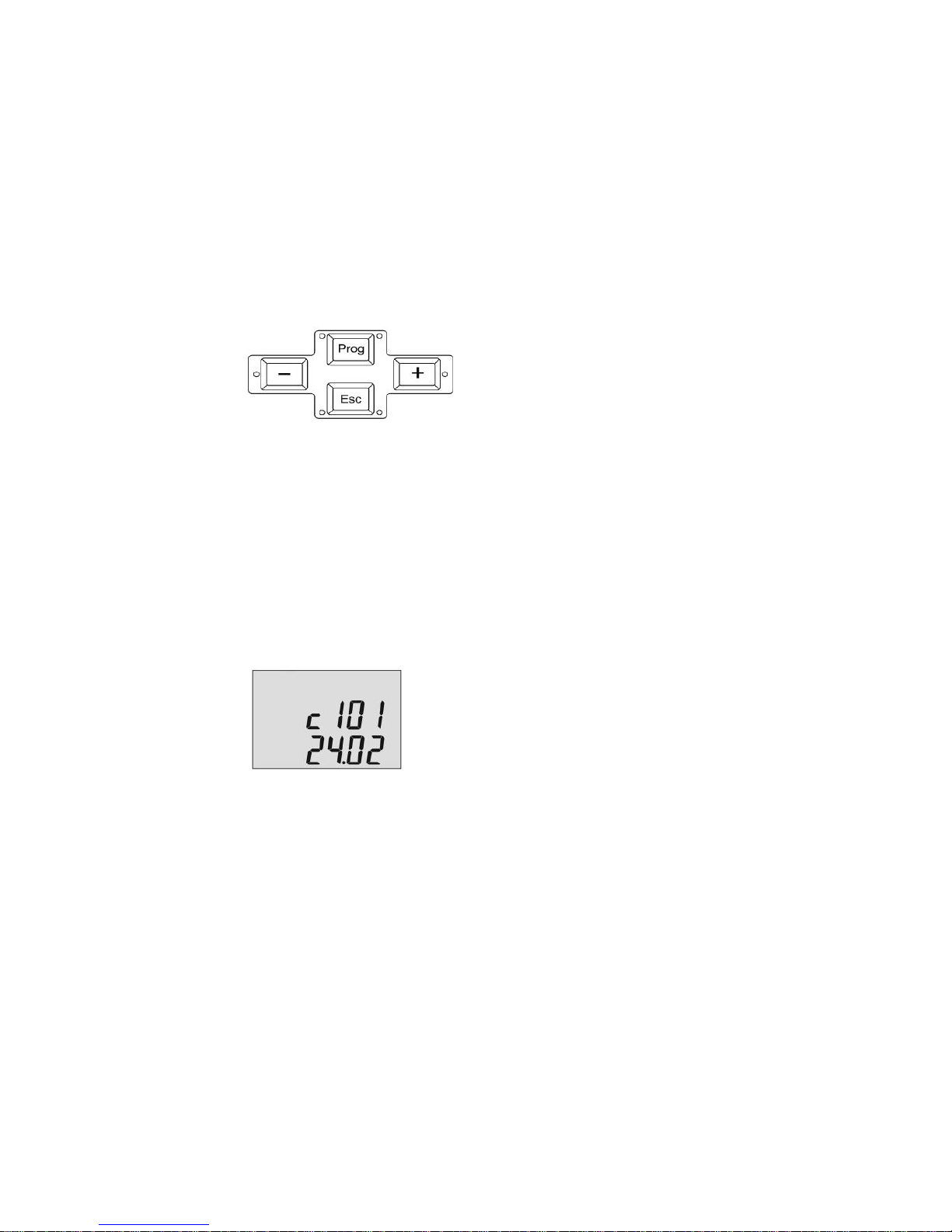
1. General key functions
Prog
Change selected submenus
Change (parameter) setting
Save value
+ (Plus) or - (Minus)
Change parameter
Change menu item
Esc
Exit setting
Keep old value
Select next higher menu level
Esc-Lang
Return to basic display
2. Version display (when starting)
c 101= Ty pe des i gnati on Ceta 101
24.02= Version display (due to update it can
differ from example shown)
5
Basic display
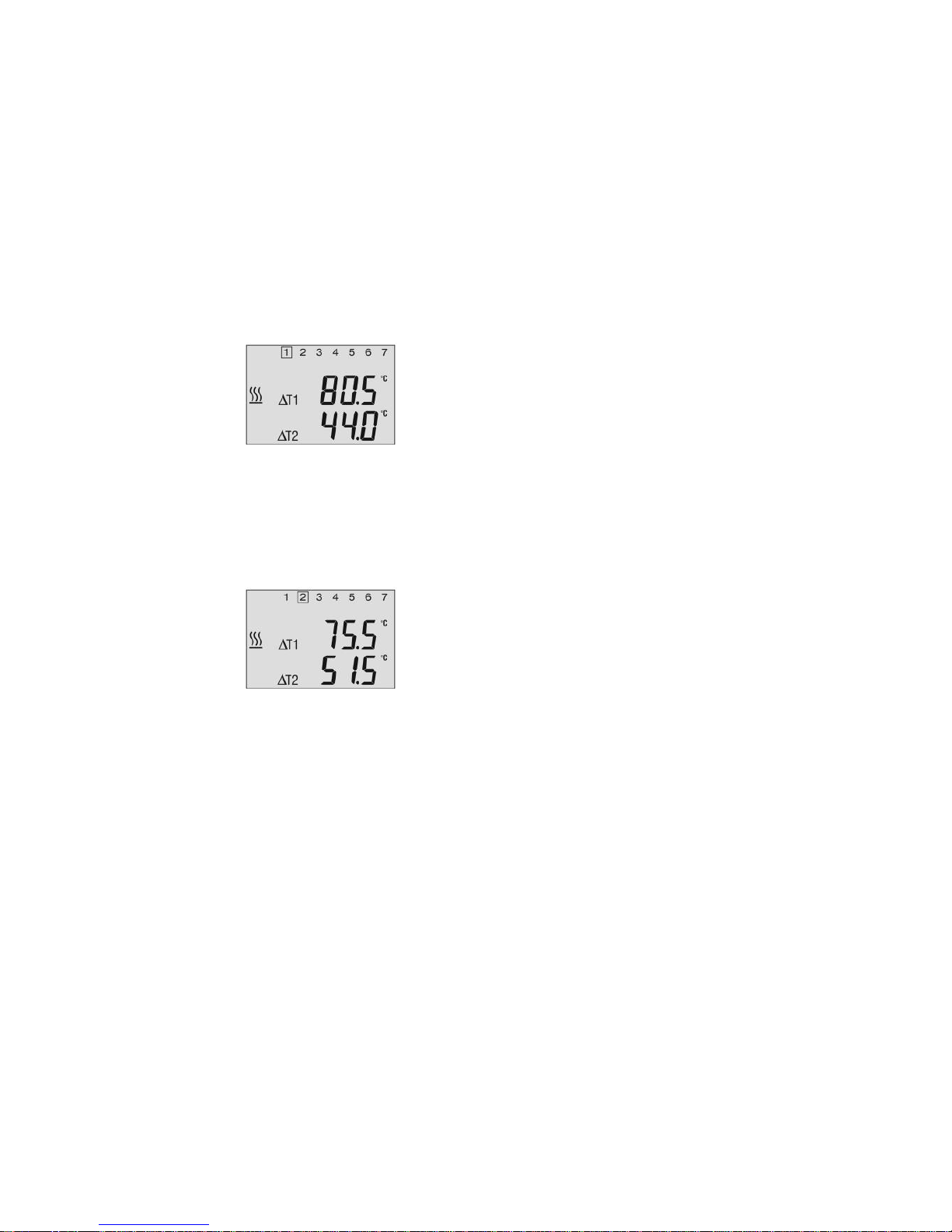
3. Basic display
1= Basic display 1
80.5°C= Temperature F3 heat supplier 1
(e.g. collector or solid fuel boiler)
44.0°C= Temperature F1 heat storage tank 1
AT1= Display pump function P1
AT2= Display pump function P2
H-GEN= Display burner block
Use + / - to switch to:
2= Basic display 2
75.5°C= Temperature F4 heat supplier 2
(e.g. collector or solid fuel boiler)
51.5°C= Temperature F2 heat storage tank 2
(if sensor F2 is available)
AT1= Display pump function P1
AT2= Display pump function P2
H-GEN= Display burner block
6
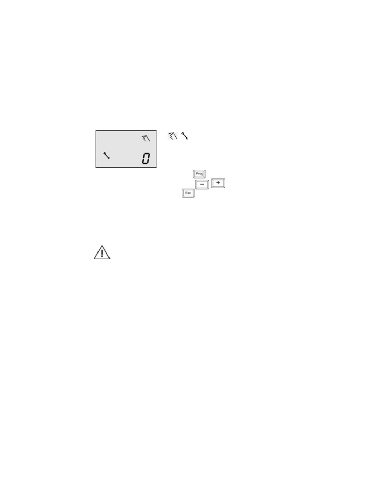
3b. Mannual switch – on pump
Mannual mode
+ Mannual mode
0... 1 Pump function
— Activated when keep pressed
— Switch – on / switch – off pump
— Escape from mannual mode
Function: Mannual mode pump activation for inspection purposes
0 = Pump off.
1 = Pump on.
Attention!
This function must be used only by the technician. When the
manual mode is on, the safety settings of the CETA 101 are deactivated! In case of faulty usage, may cause damage to the
installation (e.g stagnation)

7
Sensor resistance values
4. Sensor resistance values
Depending on temperature:
PT1000 KVT 20
T (°C) R (kOhm)
40 1.155
50 1.194
60 1.232
70 1.271
80 1.309
90 1.347
100 1.385
110 1.423
120 1.461
130 1.498
140 1.536
150 1.573
160 1.611
170 1.648
180 1.685
190 1.722
200 1.758
210 1.795
220 1.832
230 1.868
240 1.905
250 1.941
T (°C) R (kOhm)
10 1.783
12 1.812
14 1.840
16 1.869
18 1.898
20 1.928
25 2.002
30 2.078
35 2.155
40 2.234
45 2.314
50 2.395
55 2.478
60 2.563
65 2.648
70 2.735
75 2.824
80 2.914
85 3.005
90 3.098
95 3.192
100 3.287
 Loading...