

Elektromaten TS 961 Electrical Operating Instructions
en
Electrical operating instructions
Door control panel TS 961
Software 2.6 (Design and functions subject to change)
51171292 -
f 02.2013

OPERATING INSTRUCTIONS
Page
SAFETY DIRECTIONS .................................................................................................4
INST ALLATION ADVICE ..............................................................................................6
INSTALLATION OVERVIEW........................................................................................ 7
ENCLOSURE INSTALLATION .................................................................................... 8
CONNECTING THE CONTROL AND THE ELEKTROMATEN
®
..........................................................
8
LIMIT SWITCH CONNECTION
Plug - in system ...........................................................................................................9
Terminal version (until year 1997).................................................................................10
Single-limit-switches....................................................................................................10
MAINS SUPPLY............................................................................................................11
MOTOR CONNECTION (internal wiring) ....................................................................12
PHASE ROTATION.......................................................................................................12
LIMIT SWITCH - ADJUSTMENT ..................................................................................13
HARDWARE OVERVIEW ............................................................................................. 14
WIRING DIAGRAM .......................................................................................................15
CONTROL PROGRAMMING........................................................................................16
Operating mode ...........................................................................................................17
Functions .....................................................................................................................17
Reset ...........................................................................................................................18
Maintenance cycle counter ...........................................................................................18
MEMORY CHECK ........................................................................................................18
SAFETY DEVICES .......................................................................................................19
Safety nection for shutter pass - door or slack wire switch contact X2..........................19
Mounting the spiral cable .............................................................................................19
Adjustment pre-limit S5................................................................................................19
T yp 1: Resistance evaluation 1K2 with normally closed safety edge contact ................20
T yp 2: Resistance evaluation 8K2 with normally open safety edge contact...................20
T yp 3: Optical safety edge (Vitector) ............................................................................20
Function of the safety edge system ..............................................................................21
Emergency stop X3
....................................................................................................
21
Page 2

Page
FUNCTION DESCRIPTION .......................................................................................... 22
Key switch (latching) interrupt automatic closing X4 ....................................................22
Internal push button / Three push button / Key switch X5 ..............................................22
Runtime monitoring......................................................................................................22
Automatic closing ........................................................................................................22
Automatic closing interruption......................................................................................22
Photo-beam for Closing Direction X6 .........................................................................23
Ceiling pull switch / Radio control X7 ..........................................................................24
Key switch – intermediate stop X8..............................................................................24
Potential free changeover contact X9..........................................................................25
Maintenance cycle counter...........................................................................................25
Short circuit / overload monitor ....................................................................................25
OPERATING STATUS DISPLAY ..................................................................................2 6
TECHNICAL DATA.......................................................................................................29
LIFETIME / DOORCYKLES..........................................................................................30
DECLARATION OF INCORPORATION .......................................................................31
FUNCTION OVERVIEW ............................................................................................... 32
Page 3

SAFETY DIRECTIONS
Basic Directions
This control has been built in accordance with EN 12453 Industrial, commercial and garage
doors and gates - Safety in use of power operated doors - Requirements; and left the
factory in perfect condition from the point of view of safety. To maintain this condition and to
ensure safe operation, the user must observe all the directions and warnings contained in these
operating instructions.
In principle, only trained electrical craftsmen should work on electrical equipment. They must
assess the work which has been assigned to them, identify potential danger sources and take
suitable safety precautions.
®
Reconstruction of or changes to ELEKTROMATEN
the manufacturer. Original replacement parts and accessories authorised by the manufacturer
guarantee safety. Liability ceases to apply if other parts are used.
ar e only permissible with the approval of
The operational safety of an ELEKTROMATEN
®
is only guaranteed if it is used in accordance
with the regulations. The limiting values stated in the technical data should not be exceeded
under any circumstances (see corresponding sections of the operating instructions).
Safety Regulations
During the installation, initial operation, maintenance and testing of the ELEKTROMATEN®,
it is necessary to observe the safety and accident-prevention regulations valid for the specific
application.
In particular, you should observe the following regulations (this list is not exhaustive):
European normativ
- EN 12453
Saftey in use of power operated doors - Requirements
- EN 12445
Saftey in use of power operated doors - Test methods
Please check normative´s bellow.
VDE-regulations
- EN 418
Safety machinery
Emergency stop equipment functional aspects
Principles for design
- EN 60204-1 / VDE 0113-1
Safety of machinery - Electrical equipment of machines - Part 1:
General requirements
- EN 60335-1 / VDE 0700-1
Safety of household and similar electrical appliances - Part 1:
General requirements
Regulations
- Please ensure that the local regulations relating to the Safety of Operations of Doors are followed
Page 4
SAFETY DIRECTIONS
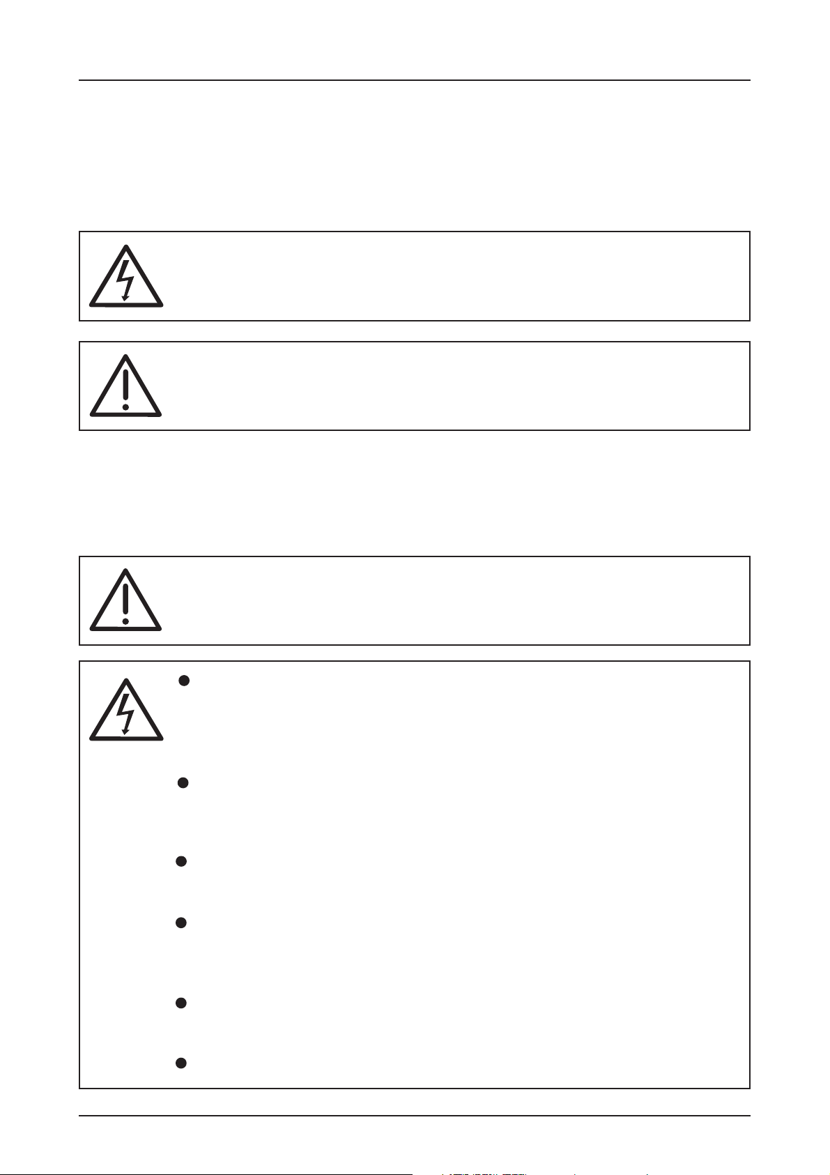
Explanation of warnings
These operating instructions contain directions which are important for using the ELEKTRO-
®
MATEN
The individual directions have the following meaning:
appropriately and safely.
DANGER
This indicates danger to the life and health of the user if the appropriate
precautions are not taken.
CAUTION
This warns that the ELEKTROMATEN® or other materials may be damaged if
the appropriate precautions are not taken.
General warnings and safety precautions
The following warnings are to be understood as a general guideline for working with the
ELEKTROMATEN® in conjunction with other devices. These directions must be observed
strictly during installation and operation.
Check that all screw connections are secure before operating the control
and adjusting the limit switches.
Please observe the safety and accident prevention regulations valid for
the specific application. The installation of the ELEKTROMATEN®, the
opening of covers or lids and electrical connection must be carried out
when the supply is switched off.
The ELEKTROMAT® must be installed with the authorised coverings and
protective devices. Care should be taken that any seals are fitted correctly
and screw couplings are tightened correctly.
In the case of ELEKTROMATEN® with a permanent mains connection, an
all-pole main switch with appropriate back-up fuse must be provided.
Check live cables and conductors regularly for insulation faults or
breakages. When a fault is detected in the cabling, the defective cabling
should be replaced after immediately switching off the mains supply.
Before starting operation, check whether the permissible mains voltage
range of the devices corresponds to the local mains voltage.
With three – phase motor connection it must have right phase rotation
Page 5

INST ALLA TION ADVICE
After the ELEKTROMATEN® is fitted we recommend the following procedure to rapidly reach
a fully functioning door.
• Installation Enclosure installation page 8
• Installation Wiring the Drive to the Control page 8
LIMIT SWITCH CONNECTION
Plug - in system page 9
LIMIT SWITCH CONNECTION
Terminal version (until year 1997) page 9
LIMIT SWITCH CONNECTION
Single-limit-switches page 1 0
• Check Mains supply page 11
• Check Phase rotation page 1 2
• Adjustmemt Limit switch - adjustment page 1 3
The door is ready to work in Dead man mode.
• Installation Safety devices page 15, 19, 20
• Programming Door functions page 1 6
The door is ready to work in automatic mode.
Check connection of external devices e.g. push button etc.
Overview to connect external devices see diagram (page 15).
After the devices are connected the programming of the control panel must be finalised.
(page 16).
Page 6
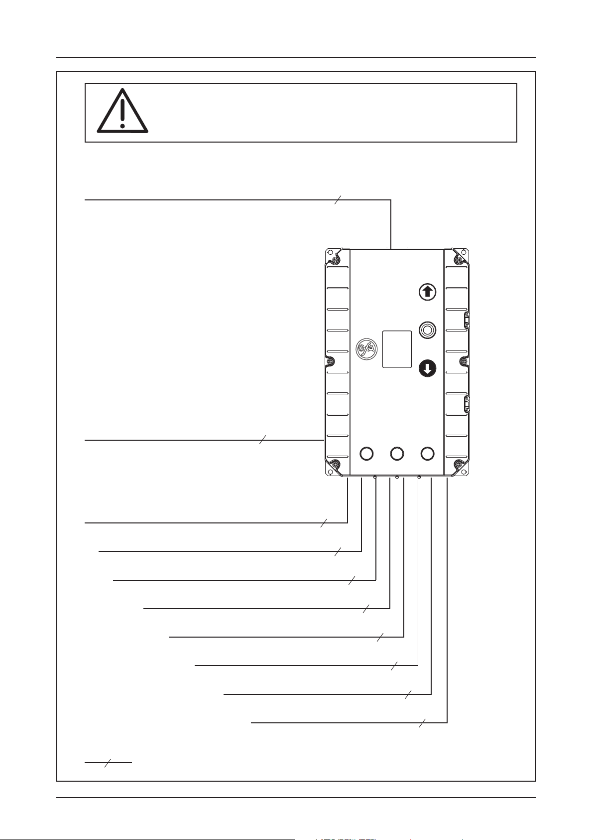
INSTALLATION OVERVIEW
Important!
Using the connection cable out side the building is not permitted.
Connection cable ELEKTROMAT
Motor and mechanical limits NES
®
for
11
Spiral cable for
Safety edge system
Mains supply
Photo-beam
Pull switch
Three push button
Key switch (latching) interrupt
automatic closing
4
Emergency stop
Key switch (latching) intermediate stop
Signal lamp
5
5
3
5
3
3
3
3
( )
Number of cores in the cable
Page 7
ENCLOSURE INSTALLATION
Before mounting the enclosure, the surface has to be checked for flatness, slope and freedom
from vibrations. Mounting must be vertical. It is important that the door can be clearly seen
from the position of the control through-out its travel.
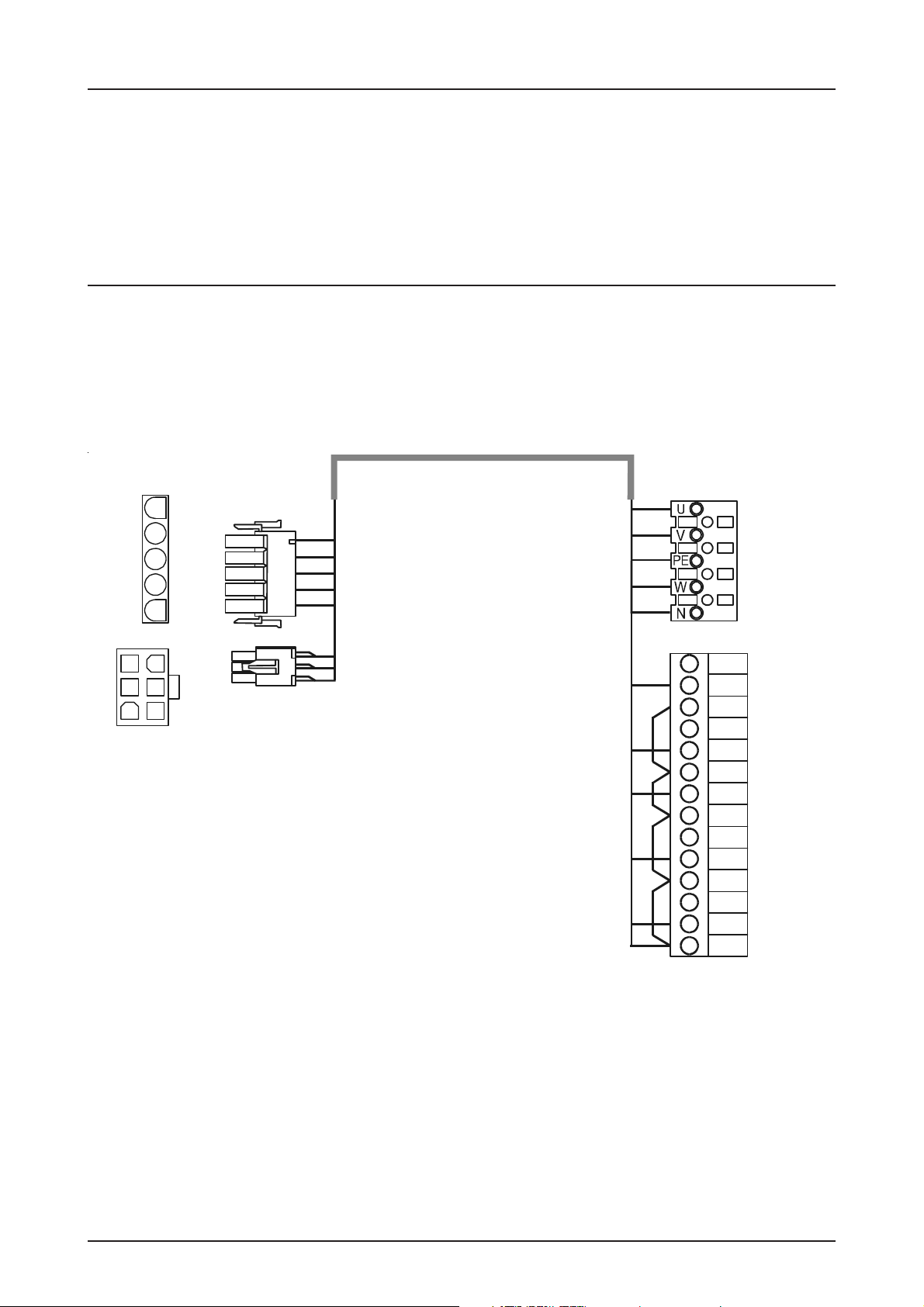
CONNECTING THE CONTROL AND THE ELEKTROMATEN
After the drive and control are fitted they can be connected with a plug-in cable. The cable
has plugs on each end and for easy fitting. The plugs for motor and control panel are different
and cannot be interchanged.
Control panel TS 961 ELEKTROMAT
PIN
- 1
- 2
- 3
- 4
- 5
PE
PIN
- 14 5 6 -
- 2
- 3
Cable Description
Motor plug to control Panel
PIN - Wire-No.
1 - 3 Phase W
2 - 2 Phase V
3 - 1 Phase U
4 - 4 Neutral (N)
5 - PE Earth
3
2
1
4
Connection cable
10
PE
8
7
9
6
5
1
2
3
4
16
15
14
10
6
5
4
9
17
8
7
13
12
11
®
Motor plugLimit switch plug
®
Limit switch plug to control panel
PIN - Wire-No.
1 - 5 supply + 24V
2 - 6 S 5 aux. limit only for Testing of safety edge system
3 - 7 open - limit
4 - 8 S 6 aux. limit for intermediate Stop or switching contact
5 - 9 close limit
6 - 10 safety circuit common limit
Page 8
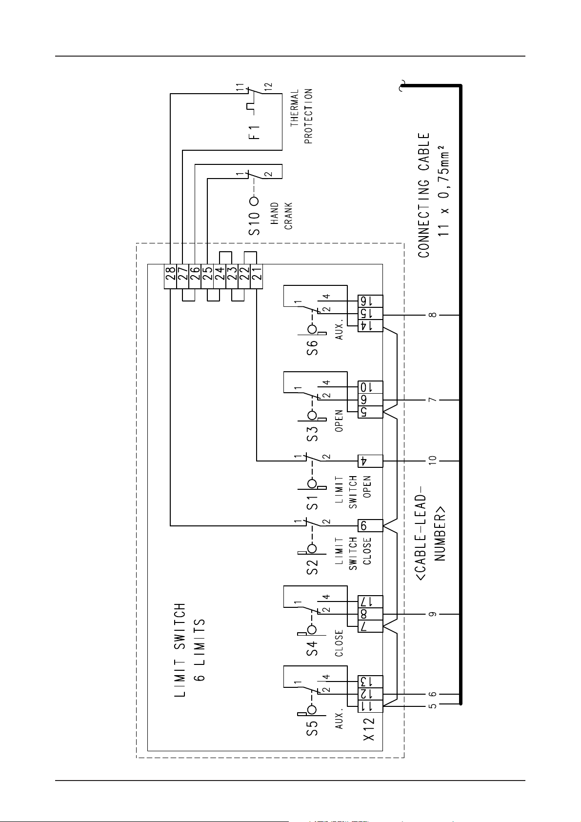
LIMIT SWITCH CONNECTION
Plug - in system
Page 9
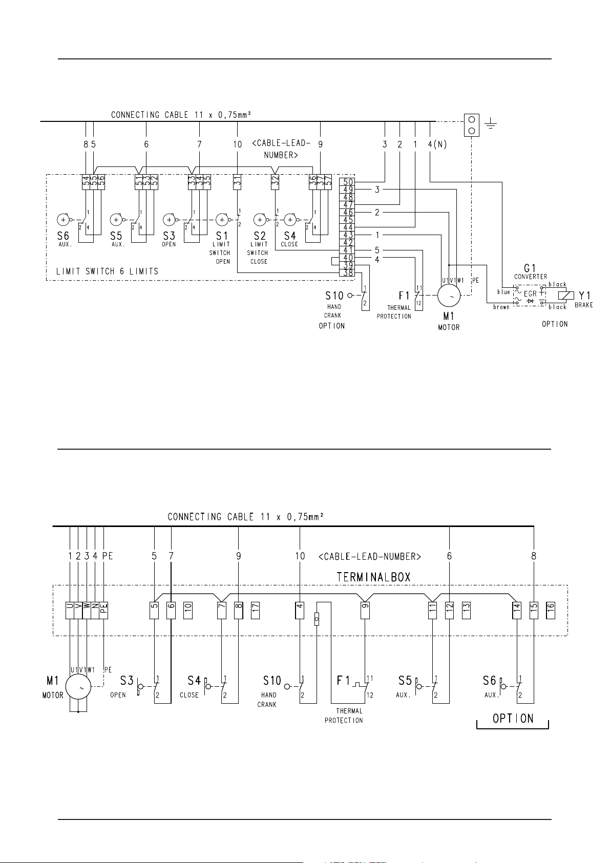
LIMIT SWITCH CONNECTION
Terminal version (until year 1997)
M
3
LIMIT SWITCH CONNECTION
Single-limit-switches
M
3
Page 10
 Loading...