

Elektromaten TS 959 Installation Instructions Manual
Pos: 1.2 /BA_Module_Manuell/Torsteuerung TS 959/01_Dec kblatt_68073 @ 7\mod_1347867455430_28.docx @ 762690 @ @ 1
aus
Installation instructions
Door control
TS 959
51171559_a_11_2012
Status: 07.11.2012
Pos: 1.3 /BA_Module_Manuell/Torsteuerung TS 959/MAL_Sei tenumbruch @ 6\mod_1344937085969_0.docx @ 758205 @ @ 1

2
Pos: 2.2 /BA_Module_Manuell/Torsteuerung TS 959/02_Le erseite_68073 @ 7\mod_1347867522263_28.docx @ 762705 @ @ 1
GfA-ELEKTROMATEN
Australia Pty Ltd
P.O. Box 267
Roseville 2069 NSW
Telephone: 02 9882 2782
Facsimile: 02 9882 2783
Email: info@gfa-elektromaten.net
Web: www.gfa-elektromaten.net
=== Ende der Liste für Textmarke inhalt3 ===

3
Pos: 3.2 /BA_Module_Manuell/Torsteuerung TS 959/03_I nha ltsverzeichnis @ 6\mod_1344867191501_28.docx @ 757614 @ @ 1
Table of contents
1 General safety information .............................................................................................. 5
2 Technical data ................................................................................................................ 6
3 Mechanical installation .................................................................................................... 7
4 Electrical installation ....................................................................................................... 8
Connection overview for connection cables ...................................................................... 9
Carrying out the electrical installation.............................................................................. 10
Mains supply ................................................................................................................... 11
Mains connection to control ............................................................................................ 11
Completion of electrical installation ................................................................................. 11
Overview of control ......................................................................................................... 12
5 Initial operation of the control ........................................................................................ 13
DES: Rapid adjustment of final limit positions ................................................................. 13
NES: rapid adjustment final limit positions ...................................................................... 14
6 Advanced electrical installation ..................................................................................... 15
External supply X1 .......................................................................................................... 15
Emergency stop X3 ......................................................................................................... 15
Relay contact X20 ........................................................................................................... 15
Control device X5 ............................................................................................................ 1 5
Spiral cable connection ................................................................................................... 15
7 Programming the control ............................................................................................... 16
8 Table of menus ............................................................................................................. 17
Operating mode .............................................................................................................. 17
Door positions ................................................................................................................. 17
Door function ................................................................................................................... 18
Safety functions .............................................................................................................. 18
Maintenance cycle counter ............................................................................................. 19
Readout of information store ........................................................................................... 20
Deleting all adjustments .................................................................................................. 20
9 Safety devices .............................................................................................................. 21
X2: Input, door safety switch ........................................................................................... 21
X3: Input, emergency stop .............................................................................................. 21
10 Description of functions ................................................................................................. 22
X1: Mains supply line for control and external supply ..................................................... 22
4
X5: Input, control device .................................................................................................. 23
Extended hold-to-run function ......................................................................................... 23
X20 potential-free relay contact ....................................................................................... 24
Force monitoring (DES only) ........................................................................................... 24
Travel time monitoring (NES only) ................................................................................... 25
Maintenance cycle counter .............................................................................................. 26
Short-circuit/overload display .......................................................................................... 26
Standby function ............................................................................................................. 2 6
11 Status display ................................................................................................................ 27
12 Explanation of symbols ................................................................................................. 31
13 Declaration of Incorporation/Declaration of Conformity .................................................. 33
=== Ende der Liste für Textmarke inhalt2 ===
Symbols
Warning - Risk of injury or danger to life!
Warning - Danger to life through electrical current!
Note - Important information!
▶
Request - Required action!
Illustrations show example products. Deviations from the delivered product are possible.

5
Pos: 4.2 /BA_Module_Manuell/Torsteuerung TS 959/04_Si c herheitshinweise @ 6\mod_1344867202506_28.doc x @ 757629 @ 1 @ 1
1 General safety information
Specified normal use
The door control is intended for a power-operated door with a drive unit.
The safe operation is only guaranteed with normal specified use. The drive unit is to be
protected from rain, moisture and aggressive ambient conditions. No liability for damage
caused by other applications or non-observance of the information in the manual.
Modifications are only permitted with the agreement of the manufacturer. Otherwise the
Manufacturer’s Declaration shall be rendered null and void.
Safety information
Installation and initial operation tasks are to be performed by trained, skilled fitters only.
Only trained electrical craftsmen are permitted to work on electrical equipment. They must
assess the tasks assigned to them, recognise potential danger zones and be able to take
appropriate safety measures.
Installation work is only to be carried out with the supply off.
Observe the applicable regulations and standards.
Coverings and safety devices
Do not operate unless corresponding coverings and safety devices are fitted/installed.
Ensure that gaskets are correctly positioned and cable glands are correctly tightened.
Spare parts
Use only original spare parts.
Pos: 4.3 /BA_Module_Manuell/Torsteuerung TS 959/MAL_Sei tenumbruch @ 6\mod_1344937085969_0.docx @ 758205 @ @ 1
6
Pos: 5.1 /BA_Module_Manuell/Torsteuerung TS 959/05_ Technische Daten @ 6\mod_1344924152708_28.docx @ 757670 @ 1 @ 1
2 Technical data
Series TS 959
Dimensions W x H x D 155 x 380 x 80 mm
Assembly vertical
Vibration
Assembly
free of vibration
Operating frequency 50/60 Hz
Supply voltage
1 N~220 V, PE
3 N~220-400 V, PE
3~220-400 V, PE
Output power for drive unit, maximum 3 kW
Backup fuse per phase, on-site 10-16 A
External mains supply:
(internal electronic backup fuse)
24 V DC
0.35 A
External mains supply: X1/L, X1/N
(backup fuse via F1 micro-fuse)
1 N~230 V
1.6
A
time-
la
g
Control inputs
24 V DC
type 10 mA
Type relay contact
floating changeover
contacts
Loading of relay contacts,
ohmic/inductive
230 V AC
1 A
Control power consumption 10 VA
Temperature range
Operation: -5..+40
Storage: +0..+50
C°
Humidity
up to 93 %
non-condensing
Class of protection of housing IP65
Compatible GfA limit switch NES; DES
Pos: 5.2 /BA_Module_Manuell/Torsteuerung TS 959/MAL_Sei tenumbruch @ 6\mod_1344937085969_0.docx @ 758205 @ @ 1

7
Pos: 6.1 /BA_Module_Manuell/Torsteuerung TS 959/06_ Mechanische_Montage @ 6\mod_1344924433864_28.docx @ 7576 88 @ 1 @ 1
3 Mechanical installation
Control installation!
Only use indoors
Mounting only on a level ground free of vibration
Only vertical mounting position permissible
Door must be visible from the assembly site
Prerequisites
The permissible loads of walls, mountings, connecting and transmission elements must not
be exceeded.
Mounting
The control is mounted via 4 elongated holes
Pos: 6.2 /BA_Module_Manuell/Torsteuerung TS 959/MAL_Sei tenumbruch @ 6\mod_1344937085969_0.docx @ 758205 @ @ 1
8
Pos: 7.1 /BA_Module_Manuell/Torsteuerung TS 959/07_E lektrische Montage @ 6\mod_1344924449762_28.docx @ 757703 @ 122 2222 @ 1
4 Electrical installation
Warning - Risk of electrocution!
Disconnect the cables (mains OFF) and check that they are voltage-free
Observe the applicable regulations and standards
Make a proper electrical connection
Use suitable tools
On-site back-up fuse and mains disconnector!
Connection to the indoor installation via an all-pole disconnector unit, with current
≥ 10 A as per EN 12453 (e.g. CEE plug connector, main switch)
Read installation instructions for drive unit!

9
Connection overview for connection cables
DES and NES
connection cables for motor
DES connection cable for limit switch
MOT X13
Motor plug
DES X12 Limit switch plug
Pin Core Term. Pin Core Term.
1 3 W Phase W 1 5/wh 1 +24 V safety circuit
2 2 V Phase
V
2 6/bn 2 Channel B (RS485)
3 1 U Phase U 3 7/gn 3 Earth
4 4 N Neutral conductor (N) 4 8/ye 4 Channel A (RS485)
5 PE PE 5 9/gy 5 Safety circuit
6 10/pk 6 8-VDC main supply
Cam-limit connecting cable
NES X12 Limit switch plug
Pin Core Term.
1 5/wh 11 Limit switch potential of +24 V, wire link at X12 5, 7, 9, 11, 14
2 6/bn 12 S5 additional limit switch, testing or safety edge function
3 7/gn 6 S3, “Open” limit switch
4 8/ye 15 S6 additional limit switch, relay function
5 9/gy 8 S4, “Close” limit switch
6 10/pk 4 Safety circuit
10
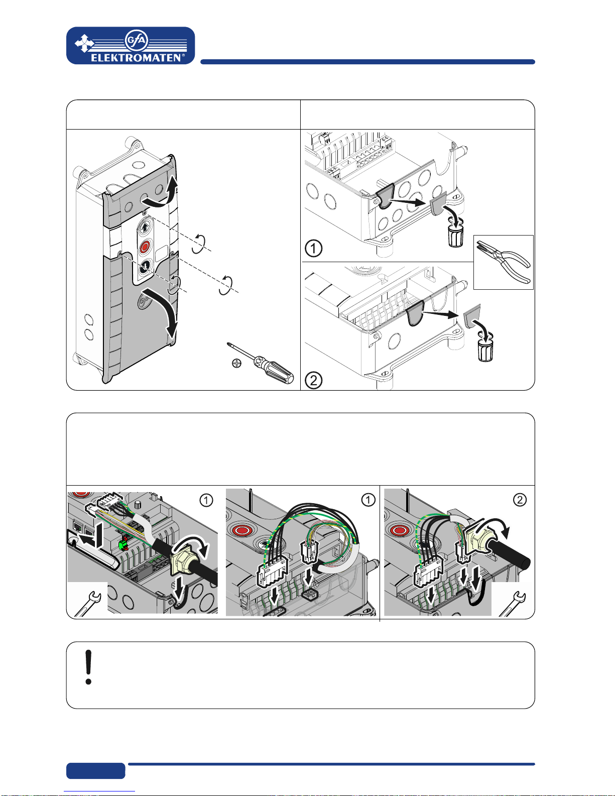
Carrying out the electrical installation
▶ Remove the covers. ▶ Open cable conduit ① or ②.
▶ Insert and connect control/drive connection cable in the open cable conduit ① (from
below) or ② (from above).
▶ Tighten cable gland.
Caution - Avoid damage to components!
Open cable conduit with suitable tool
Install cable entries and/or cable glands
 Loading...