

Elektro-Automatik PS 9000 3U, PS 9040-170 3U, PS 9080-170 3U, PS 9200-70 3U, PS 9360-40 3U User guide
...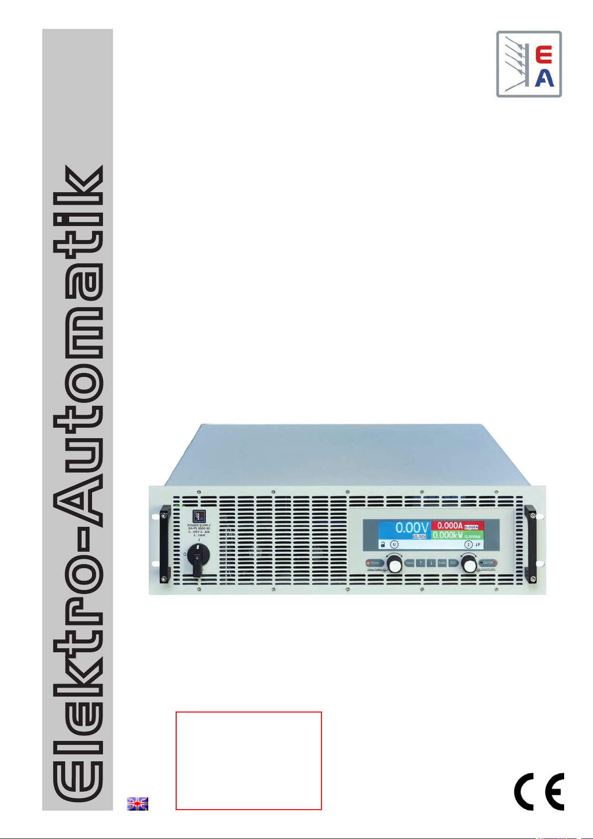
Operating Guide
PS 9000 3U
DC High Efficiency Power Supply
Attention! This document is only
valid for devices with TFT dis-
play and rmwares “KE: 3.07”
(standard version) or “KE: 2.11”
(GPIB, 3W) and “HMI: 2.03” or
higher. For availability of up-
Elektro-Automatik
dates for your device check our
website or contact us.
Doc ID: PS93UTEN
Revision: 09
Date: 02/2020


TABLE OF CONTENTS
GENERAL
1
1.1 About this document ......................................5
1.1.1 Retention and use ..........................................5
1.1.2 Copyright ........................................................5
1.1.3 Validity ............................................................5
1.1.4 Explanation of symbols ..................................5
1.2 Warranty .........................................................5
1.3 Limitation of liability ........................................5
1.4 Disposal of equipment ...................................6
1.5 Product key ....................................................6
1.6 Intended usage ..............................................6
1.7 Safety .............................................................7
1.7.1 Safety notices .................................................7
1.7.2 Responsibility of the user...............................8
1.7.3 Responsibility of the operator .......................8
1.7.4 User requirements .........................................8
1.7.5 Alarm signals ..................................................9
1.8 Technical data ................................................9
1.8.1 Approved operating conditions ......................9
1.8.2 General technical data ...................................9
1.8.3 Specic technical data (400 V AC models) . 10
1.8.4 Specic technical data (208 V AC models) . 18
1.8.5 Views ............................................................26
1.8.6 Control elements ..........................................29
1.9 Construction and function ............................30
1.9.1 General description ......................................30
1.9.2 Block diagram ..............................................30
1.9.3 Scope of delivery .........................................31
1.9.4 Accessories ..................................................31
1.9.5 Options .........................................................31
1.9.6 The control panel (HMI) ...............................32
1.9.7 USB port .......................................................34
1.9.8 Ethernet port ................................................34
1.9.9 Analog interface ...........................................35
1.9.10 Share Bus connection .................................35
1.9.11 Sense connector (remote sensing) .............35
1.9.12 GPIB port (optional) .....................................35
INSTALLATION &
2
COMMISSIONING
2.1 Transport and storage .................................36
2.1.1 Transport ......................................................36
2.1.2 Packaging ....................................................36
2.1.3 Storage .........................................................36
2.2 Unpacking and visual check ........................36
2.3 Installation ....................................................36
2.3.1 Safety procedures before installation and
use ................................................................36
2.3.2 Preparation ...................................................37
2.3.3 Installing the device .....................................37
2.3.4 Connection to AC supply .............................38
2.3.5 Connection to DC loads ...............................41
PS 9000 3U Series
2.3.6 Connection of remote sensing ....................42
2.3.7 Grounding of the DC output ........................43
2.3.8 Connecting the “Share” bus ........................43
2.3.9 Connecting the analog interface .................43
2.3.10 Connecting the USB port .............................43
2.3.11 Initial commission .........................................44
2.3.12 Initial network setup .....................................44
2.3.13 Commission after a rmware update or a
long period of non-use .................................44
OPERATION AND APPLICATION
3
3.1 Important notes ............................................45
3.1.1 Personal safety ............................................45
3.1.2 General .........................................................45
3.2 Operating modes .........................................45
3.2.1 Voltage regulation / Constant voltage .........45
3.2.2 Current regulation / constant current / current
limiting ..........................................................46
3.2.3 Power regulation / constant power / power
limiting ..........................................................46
3.3 Alarm conditions ..........................................47
3.3.1 Power Fail ...................................................47
3.3.2 Overtemperature ..........................................47
3.3.3 Overvoltage ..................................................47
3.3.4 Overcurrent ..................................................47
3.3.5 Overpower ....................................................47
3.4 Manual operation .........................................48
3.4.1 Switching the device on ...............................48
3.4.2 Switching the device o ...............................48
3.4.3 Conguration in the setup menu .................48
3.4.4 Adjustment limits ..........................................53
3.4.5 Manual adjustment of set values .................54
3.4.6 Switching the main screen view ..................54
3.4.7 The quick menu ...........................................55
3.4.8 Switching the DC output on or o ...............55
3.5 Remote control .............................................56
3.5.1 General .........................................................56
3.5.2 Control locations ..........................................56
3.5.3 Remote control via a digital interface ..........56
3.5.4 Remote control via the analog interface
(AI) ................................................................57
3.6 Alarms and monitoring .................................61
3.6.1 Denition of terms ........................................61
3.6.2 Device alarm handling .................................61
3.7 Control panel (HMI) lock ..............................62
3.8 Loading and saving a user prole ...............63
3.9 Other applications ........................................64
3.9.1 Parallel operation in Share bus mode .........64
3.9.2 Series connection ........................................65
3.9.3 Operation as battery charger .......................65
3.9.4 Two quadrants operation (2QO) ..................66
EA Elektro-Automatik GmbH
Helmholtzstr. 31-37 • 41747 Viersen
Germany
Fon: +49 2162 / 3785-0
Fax: +49 2162 / 16230
www.elektroautomatik.de
ea1974@elektroautomatik.de
Page 3

SERVICE AND MAINTENANCE
4
4.1 Maintenance / cleaning ................................68
4.2 Fault nding / diagnosis / repair...................68
4.2.1 Firmware updates ........................................68
4.3 Calibration (readjustment) ...........................69
4.3.1 Preface .........................................................69
4.3.2 Preparation ...................................................69
4.3.3 Calibration procedure ..................................69
CONTACT AND SUPPORT
5
5.1 Repairs .........................................................71
5.2 Contact options ............................................71
PS 9000 3U Series
EA Elektro-Automatik GmbH
Helmholtzstr. 31-37 • 41747 Viersen
Germany
Fon: +49 2162 / 3785-0
Fax: +49 2162 / 16230
www.elektroautomatik.de
ea1974@elektroautomatik.de
Page 4
PS 9000 3U Series
1. General
1.1 About this document
1.1.1 Retention and use
This document is to be kept in the vicinity of the equipment for future reference and explanation of the operation of
the device. This document is to be delivered and kept with the equipment in case of change of location and/or user.
1.1.2 Copyright
Reprinting, copying, also partially, usage for other purposes as foreseen of this manual are forbidden and breach
may lead to legal process.
1.1.3 Validity
This manual is valid for the following equipment with colour TFT display, including derived variants.
Model Article nr.. Model Article nr.. Model Article nr..
PS 9040-170 3U 06230250 PS 9080-340 3U 06230257 PS 9080-510 3U 06230264
PS 9080-170 3U 06230251 PS 9200-140 3U 06230258 PS 9200-210 3U 06230265
PS 9200-70 3U 06230252 PS 9360-80 3U 06230259 PS 9360-120 3U 06230266
PS 9360-40 3U 06230253 PS 9500-60 3U 06230260 PS 9500-90 3U 06230267
PS 9500-30 3U 06230254 PS 9750-40 3U 06230261 PS 9750-60 3U 06230268
PS 9750-20 3U 06230255 PS 91000-30 3U 06230262 PS 91000-40 3U 06230270
PS 9040-340 3U 06230256 PS 9040-510 3U 06230263 PS 91500-30 3U 06230269
1.1.4 Explanation of symbols
Warning and safety notices as well as general notices in this document are shown in a box with a symbol as follows:
Symbol for a life threatening danger
Symbol for general safety notices (instructions and damage protection bans) or important information for operation
Symbol for general notices
1.2 Warranty
EA Elektro-Automatik guarantees the functional competence of the applied technology and the stated performance
parameters. The warranty period begins with the delivery of free from defects equipment.
Terms of guarantee are included in the general terms and conditions (TOS) of EA Elektro-Automatik.
1.3 Limitation of liability
All statements and instructions in this manual are based on current norms and regulations, up-to-date technology
and our long term knowledge and experience. The manufacturer accepts no liability for losses due to:
• Usage for purposes other than designed
• Use by untrained personnel
• Rebuilding by the customer
• Technical changes
• Use of not authorized spare parts
The actual delivered device(s) may dier from the explanations and diagrams given here due to latest technical
changes or due to customized models with the inclusion of additionally ordered options.
EA Elektro-Automatik GmbH
Helmholtzstr. 31-37 • 41747 Viersen
Germany
Fon: +49 2162 / 3785-0
Fax: +49 2162 / 16230
www.elektroautomatik.de
ea1974@elektroautomatik.de
Page 5
PS 9000 3U Series
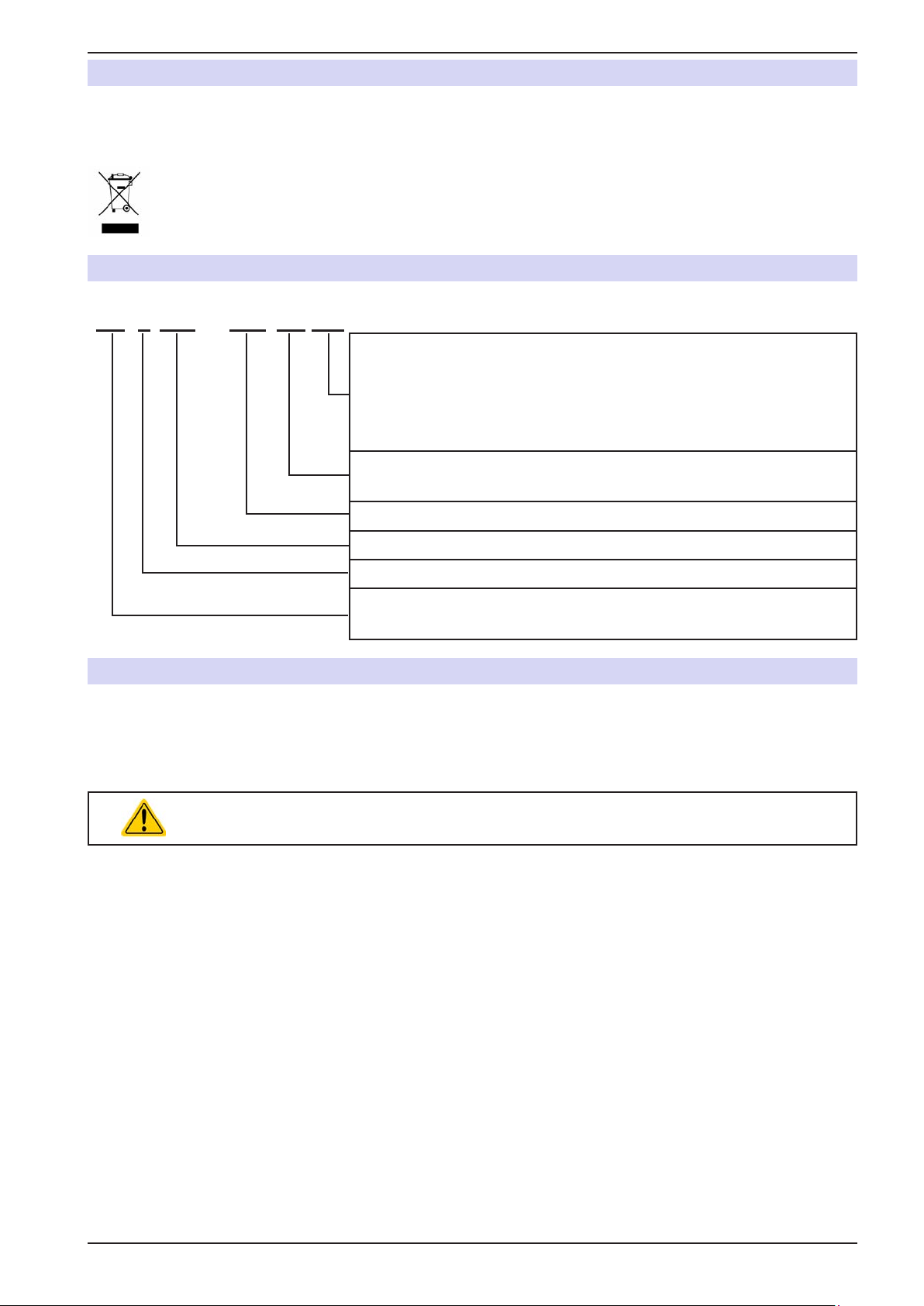
1.4 Disposal of equipment
A piece of equipment which is intended for disposal must, according to European laws and regulations (ElektroG,
WEEE) be returned to the manufacturer for scrapping, unless the person operating the piece of equipment or another, delegated person is conducting the disposal. Our equipment falls under these regulations and is accordingly
marked with the following symbol:
1.5 Product key
Decoding of the product description on the label, using an example:
PS 9 080 - 510 3U zzz
Field for identication of installed options and/or special models
S01...S0x = Special models
HS = High Speed option installed
3W = Option 3W installed (GPIB port instead of Ethernet port)
US208V = 208 V model for US market
Construction (not stated everywhere):
3U = 19" frame with 3U
Maximum current of the device in Ampere
Maximum voltage of the device in Volt
Series : 9 = Series 9000
Type identication:
PS = Power Supply, usually programmable
1.6 Intended usage
The equipment is intended to be used, if a power supply or battery charger, only as a variable voltage and current
source, or, if an electronic load, only as a variable current sink.
Typical application for a power supply is DC supply to any relevant user, for a battery charger the charging of various battery types and for electronic loads the replacement of an ohmic resistor by an adjustable DC current sink
in order to load relevant voltage and current sources of any type.
• Claims of any sort due to damage caused by non-intended usage will not be accepted.
• All damage caused by non-intended usage is solely the responsibility of the operator.
EA Elektro-Automatik GmbH
Helmholtzstr. 31-37 • 41747 Viersen
Germany
Fon: +49 2162 / 3785-0
Fax: +49 2162 / 16230
www.elektroautomatik.de
ea1974@elektroautomatik.de
Page 6
1.7 Safety
1.7.1 Safety notices
Mortal danger - Hazardous voltage
• Electrical equipment operation means that some parts can be under dangerous voltage.
Therefore all parts under voltage must be covered! This basically applies to all models,
though 40 V models according to SELV can not generate hazardous DC voltage!
• All work on connections must be carried out under zero voltage (output not connected to
load) and may only be performed by qualied and informed persons. Improper actions
can cause fatal injury as well as serious material damage!
• Never touch cables or connectors directly after unplugging from mains supply as the
danger of electric shock remains!
• Never touch the contacts on DC output terminal directly after switching o the DC
output, because there still can dangerous voltage present, sinking more or less slowly
depending on the load! There also can be dangerous potential between negative DC
output to PE or positive DC output to PE due to charged X capacitors.
• Always follow 5 safety rules when working with electric devices:
• Disconnect completely
• Secure against reconnection
• Verify that the system is dead
• Carry out earthing and short-circuiting
• Provide protection from adjacent live parts
PS 9000 3U Series
• The equipment must only be used as intended
• The equipment is only approved for use within the connection limits stated on the product label.
• Do not insert any object, particularly metallic, through the ventilator slots
• Avoid any use of liquids near the equipment. Protect the device from wet, damp and conden-
sation.
• For power supplies and battery chargers: do not connect users, particularly low resistance, to
devices under power; sparking may occur which can cause burns as well as damage to the
equipment and to the user.
• For electronic loads: do not connect power sources to equipment under power, sparking may
occur which can cause burns as well as damage to the equipment and to the source.
• ESD regulations must be applied when plugging interface cards or modules into the relative slot
• Interface cards or modules may only be attached or removed after the device is switched o.
It isn’t necessary to open the device.
• Do not connect external power sources with reversed polarity to DC input or outputs! The
equipment will be damaged.
• For power supply devices: avoid where possible connecting external power sources to the
DC output, and never those that can generate a higher voltage than the nominal voltage of
the device.
• For electronic loads: do not connect a power source to the DC input which can generate a
voltage more than 120% of the nominal input voltage of the load. The equipment isn’t protected
against over voltage and may be irreparably damaged.
• Never insert a network cable which is connected to Ethernet or its components into the master-slave socket on the back side of the device!
• Always congure the various protecting features against overvoltage overpower etc. for sensitive loads to what the currently used application requires
EA Elektro-Automatik GmbH
Helmholtzstr. 31-37 • 41747 Viersen
Germany
Fon: +49 2162 / 3785-0
Fax: +49 2162 / 16230
www.elektroautomatik.de
ea1974@elektroautomatik.de
Page 7
PS 9000 3U Series
1.7.2 Responsibility of the user
The equipment is in industrial operation. Therefore the operators are governed by the legal safety regulations.
Alongside the warning and safety notices in this manual the relevant safety, accident prevention and environmental
regulations must also be applied. In particular the users of the equipment:
• must be informed of the relevant job safety requirements
• must work to the dened responsibilities for operation, maintenance and cleaning of the equipment
• before starting work must have read and understood the operating manual
• must use the designated and recommended safety equipment.
1.7.3 Responsibility of the operator
Operator is any natural or legal person who uses the equipment or delegates the usage to a third party, and is
responsible during its usage for the safety of the user, other personnel or third parties.
The equipment is in industrial operation. Therefore the operators are governed by the legal safety regulations.
Alongside the warning and safety notices in this manual the relevant safety, accident prevention and environmental
regulations must also be applied. In particular the operator has to
• be acquainted with the relevant job safety requirements
• identify other possible dangers arising from the specic usage conditions at the work station via a risk assessment
• introduce the necessary steps in the operating procedures for the local conditions
• regularly control that the operating procedures are current
• update the operating procedures where necessary to reect changes in regulation, standards or operating con-
ditions.
• dene clearly and unambiguously the responsibilities for operation, maintenance and cleaning of the equipment.
• ensure that all employees who use the equipment have read and understood the manual. Furthermore the users
are to be regularly schooled in working with the equipment and the possible dangers.
• provide all personnel who work with the equipment with the designated and recommended safety equipment
Furthermore, the operator is responsible for ensuring that the device is at all times technically t for use.
1.7.4 User requirements
Any activity with equipment of this type may only be performed by persons who are able to work correctly and
reliably and satisfy the requirements of the job.
• Persons whose reaction capability is negatively inuenced by e.g. drugs, alcohol or medication may not operate
the equipment.
• Age or job related regulations valid at the operating site must always be applied.
Danger for unqualied users
Improper operation can cause person or object damage. Only persons who have the necessary
training, knowledge and experience may use the equipment.
Delegated persons are those who have been properly and demonstrably instructed in their tasks and the attendant dangers.
Qualied persons are those who are able through training, knowledge and experience as well as knowledge of
the specic details to carry out all the required tasks, identify dangers and avoid personal and other risks.
EA Elektro-Automatik GmbH
Helmholtzstr. 31-37 • 41747 Viersen
Germany
Fon: +49 2162 / 3785-0
Fax: +49 2162 / 16230
www.elektroautomatik.de
ea1974@elektroautomatik.de
Page 8

PS 9000 3U Series
1.7.5 Alarm signals
The equipment oers various possibilities for signalling alarm conditions, however, not for danger situations. The
signals may be optical (on the display as text) acoustic (piezo buzzer) or electronic (pin/status output of an analog
interface). All alarms will cause the device to switch o the DC output.
The meaning of the signals is as follows:
Signal OT
(OverTemperature)
• Overheating of the device
• DC output will be switched o temporarily
• Non-critical
Signal OVP
(OverVoltage)
• Overvoltage shutdown of the DC output due to high voltage entering the device or generated by the device itself due to a defect
• Critical! The device and/or the load could be damaged
Signal OCP
(OverCurrent)
Signal OPP
(OverPower)
Signal PF
(Power Fail)
• Shutdown of the DC output due to excess of the preset limit
• Non-critical, protects the load from excessive current consumption
• Shutdown of the DC output due to excess of the preset limit
• Non-critical, protects the load from excessive power consumption
• DC output shutdown due to AC undervoltage or defect of the AC input circuit
• Critical on overvoltage! AC mains input circuit could take damage
1.8 Technical data
1.8.1 Approved operating conditions
• Use only inside dry buildings
• Ambient temperature 0-50°C (32-122 °F)
• Operational altitude: max. 2000 m (1.242 mi) above sea level
• Maximum 80% humidity, non-condensing
1.8.2 General technical data
Display: Color TFT display, 480pt x 128pt
Controls: 2 rotary knobs with button function, 5 pushbuttons
The nominal values for the device determine the maximum adjustable ranges.
EA Elektro-Automatik GmbH
Helmholtzstr. 31-37 • 41747 Viersen
Germany
Fon: +49 2162 / 3785-0
Fax: +49 2162 / 16230
www.elektroautomatik.de
ea1974@elektroautomatik.de
Page 9
PS 9000 3U Series
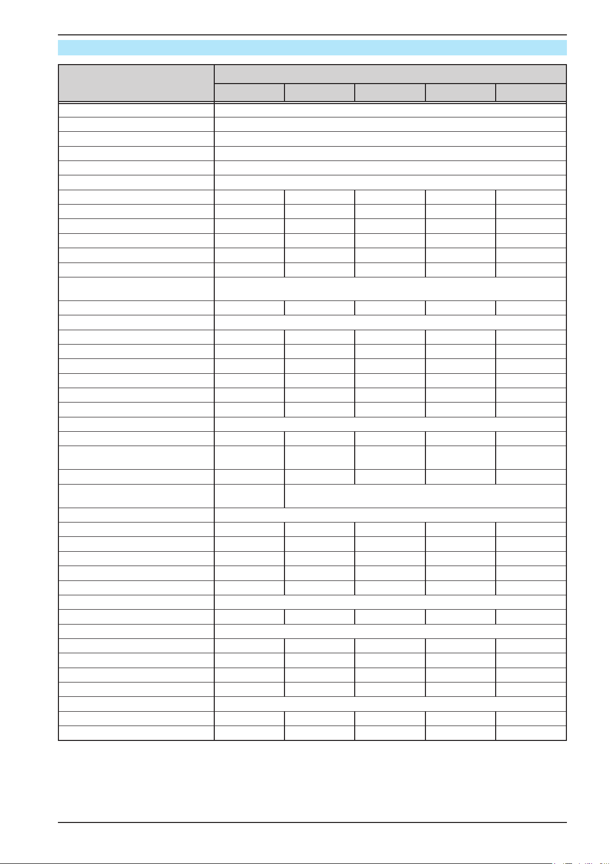
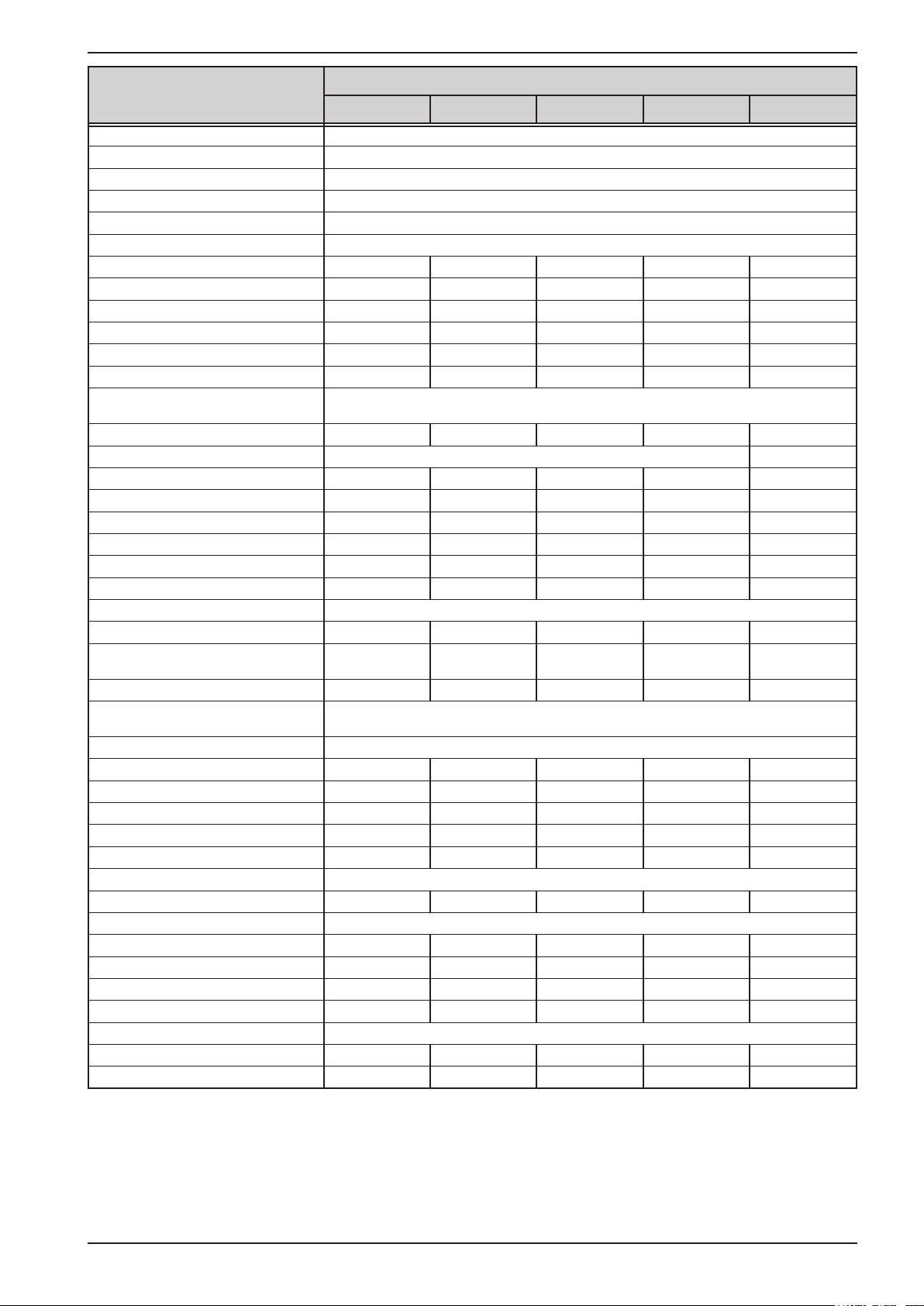
1.8.3 Specic technical data (400 V AC models)
Model 400 V
3.3 kW / 5 kW
AC Input
Voltage (L-L) 340...460 V AC, 45 - 65 Hz
Input connection 2ph,PE
Leak current < 3.5 mA
Power factor > 0.99
DC Output
Max. output voltage U
Max. output current I
Max. output power P
Overvoltage protection range 0...44 V 0...88 V 0...220 V 0...396 V 0...550 V
Overcurrent protection range 0...187 A 0...187 A 0...77 A 0...44 A 0...33 A
Overpower protection range 0…3.63 kW 0…5.5 kW 0…5.5 kW 0…5.5 kW 0…5.5 kW
Temperature coecient for set
values Δ/K
Output capacitance (approx.) 8500 μF 8500 μF 2500 μF 400 μF 250 μF
Voltage regulation
Adjustment range 0...40.8 V 0...81.6 V 0...204 V 0...367.2 V 0...510 V
Accuracy
(1
(at 23±5°C / 73±9°F)) < 0.1% U
Line regulation at ±10% ΔU
Load regulation at 0...100% load < 0.05% U
Rise time 10...90% Max. 30 ms Max. 30 ms Max. 30 ms Max. 30 ms Max. 30 ms
Settling time after load step < 1.5 ms < 1.5 ms < 1.5 ms < 1.5 ms < 1.5 ms
Display: Resolution See section „1.9.6.4. Resolution of the displayed values“
Display: Accuracy
(2
Ripple
Remote sensing compensation Max. 5% U
Fall time at no load after switching
DC output o
Current regulation
Adjustment range 0...173.4 A 0...173.4 A 0...71.4 A 0...40.8 A 0...30.6 A
Accuracy
(1
(at 23±5°C / 73±9°F)) < 0.2% I
Line regulation at ±10% ΔU
Load regulation at 0...100% ΔU
(2
Ripple
Display: Resolution See section „1.9.6.4. Resolution of the displayed values“
Display: Accuracy
Power regulation
Adjustment range 0…3.36 kW 0…5.1 kW 0…5.1 kW 0…5.1 kW 0…5.1 kW
Accuracy
(1
(at 23±5°C / 73±9°F)) < 1% P
Line regulation at ±10% ΔU
Load reg. at 10-90% ΔU
Display: Resolution See section „1.9.6.4. Resolution of the displayed values“
Display: Accuracy
Eciency
(3
Max
Max
Max
AC
(4
AC
(4
AC
* ΔI
OUT
(4
PS 9040-170 PS 9080-170 PS 9200-70 PS 9360-40 PS 9500-30
40 V 80 V 200 V 360 V 500 V
170 A 170 A 70 A 40 A 30 A
3.3 kW 5 kW 5 kW 5 kW 5 kW
Voltage / current: 100 ppm
Max
Max
Max
< 0.1% U
Max
< 0.02% U
< 0.05% U
≤ 0.2% U
Max
< 200 mVPP
< 16 mV
RMS
Max. 5% U
Max
< 0.02% U
≤ 0.2% U
Max
< 200 mVPP
< 16 mV
RMS
- Down from 100% to <60 V: less than 10 s
Max
Max
Max
Max
Max
< 0.2% I
Max
< 0.05% I
< 0.15% I
< 80 mA
≤ 0.2% I
< 1% P
RMS
Max
Max
< 0.05% P
< 0.75% P
≤ 0.8% P
Max
OUT
OUT
Max
< 0.05% I
< 0.15% I
< 80 mA
≤ 0.2% I
RMS
Max
Max
< 0.05% P
< 0.75% P
≤ 0.75% P
≈ 93% ≈ 93% ≈ 95% ≈ 95% ≈ 95,5%
Max
Max
Max
Max
Max
Max
Max
< 0.1% U
Max
< 0.02% U
< 0.05% U
≤ 0.2% U
Max
< 300 mVPP
< 40 mV
RMS
Max. 5% U
< 0.2% I
< 0.05% I
< 0.15% I
< 22 mA
≤ 0.2% I
< 1% P
Max
Max
Max
RMS
Max
Max
< 0.05% P
< 0.75% P
≤ 0.8% P
Max
Max
Max
Max
Max
Max
< 0.1% U
Max
< 0.02% U
< 0.05% U
≤ 0.2% U
Max
< 550 mVPP
< 65 mV
RMS
Max. 5% U
< 0.2% I
< 0.05% I
< 0.15% I
< 5.2 mA
≤ 0.2% I
< 1% P
Max
Max
Max
RMS
Max
Max
< 0.05% P
< 0.75% P
≤ 0.8% P
Max
Max
Max
Max
Max
Max
< 0.1% U
< 0.02% U
< 0.05% U
≤ 0.2% U
< 350 mVPP
< 70 mV
Max. 5% U
< 0.2% I
< 0.05% I
< 0.15% I
< 16 mA
≤ 0.2% I
< 1% P
< 0.05% P
< 0.75% P
≤ 0.8% P
Max
Max
Max
Max
RMS
Max
Max
Max
Max
RMS
Max
Max
Max
Max
Max
(1 Related to the nominal values, the accuracy denes the maximum deviation between an adjusted values and the true (actual) value.
Example: a 80 V model has min. 0.1% voltage accuracy, that is 80 mV. When adjusting the voltage to 5 V, the actual value is allowed to dier max. 80 mV, which
means it might be between 4.92 V and 5.08 V.
(2 RMS value: LF 0...300 kHz, PP value: HF 0...20MHz
(3 Typical value at 100% output voltage and 100% power
(4 The display error adds to the error of the related actual value on the DC output
EA Elektro-Automatik GmbH
Helmholtzstr. 31-37 • 41747 Viersen
Germany
Fon: +49 2162 / 3785-0
Fax: +49 2162 / 16230
www.elektroautomatik.de
ea1974@elektroautomatik.de
Page 10
PS 9000 3U Series
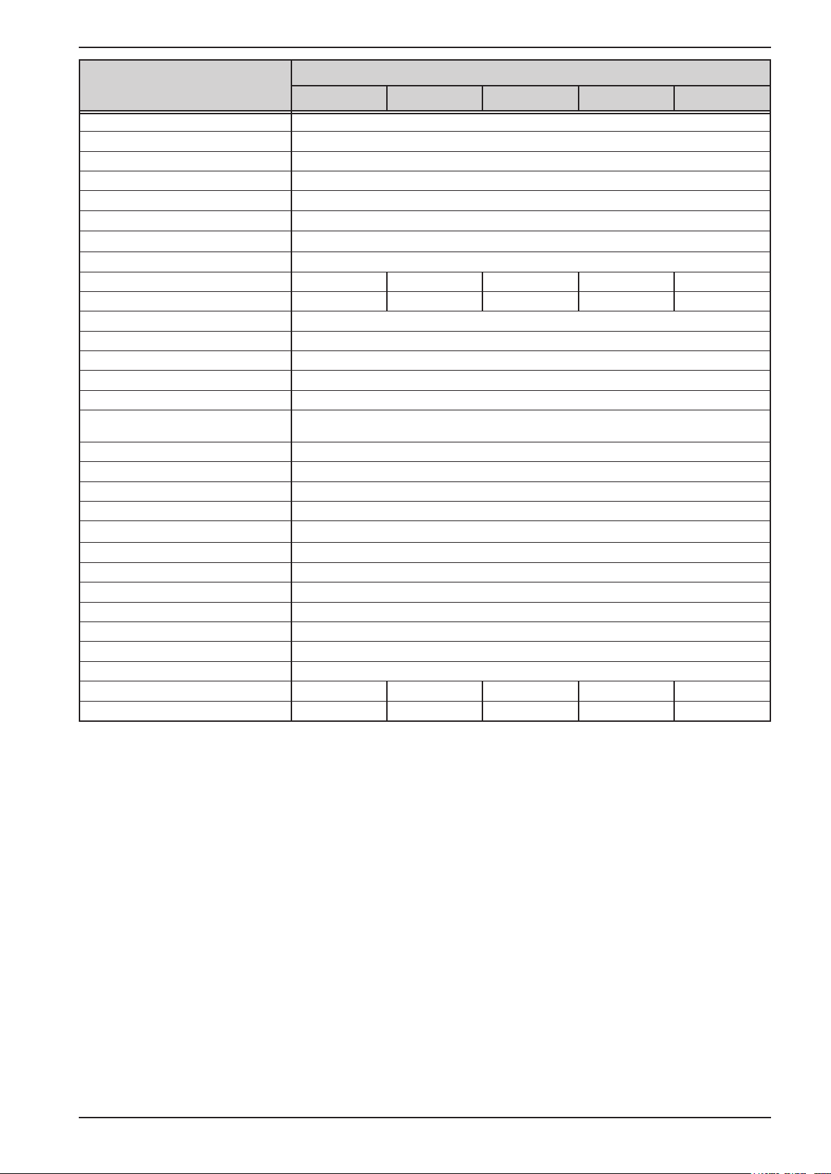
Model 400 V
3.3 kW / 5 kW
Analog interface
Set value inputs U, I, P
Actual value outputs U, I
Control signals DC on/o, remote control on/o
Status signals CV, OVP, OT, OCP, OPP, PF, DC on/o
Galvanic isolation to the device Max. 725 V DC
Sample rate of inputs 500 Hz
Insulation Allowed oat (potential shift) on the DC output:
Negative terminal to PE Max. ±400 V DC ±400 V DC ±400 V DC ±400 V DC ±725 V DC
Positive terminal to PE Max. ±400 V DC ±400 V DC ±600 V DC ±600 V DC ±1000 V DC
Miscellaneous
Cooling Temperature controlled fans, front inlet, rear exhaust
Ambient temperature 0..50°C (32...122°F)
Storage temperature -20...70°C (-4...158°F)
Humidity < 80%, not condensing
Standards
Overvoltage category 2
Protection class 1
Pollution degree 2
Operational altitude <2000 m (1,242 mi)
Digital interfaces
Featured 1x USB-B, 1x Ethernet (2, 1x GPIB (optional with option 3W)
Galvanic isolation from device Max. 725 V DC
Connectors
Rear side Share Bus, DC output, AC input, remote sensing, analog interface, USB-B, Ethernet
Dimensions
Enclosure (WxHxD) 19“ x 3 U x 609 mm (24”)
Total (WxHxD) 483 x 133 x 714 mm (19” x 5,2” x 28,1”)
Weight
Article number
(1
(3
PS 9040-170 PS 9080-170 PS 9200-70 PS 9360-40 PS 9500-30
EN 61010-1:2010
EMC TÜV approved acc. IEC 61000-6-2:2005 and IEC 61000-6-3:2006 Class B
≈17 kg (37.5 lb) ≈17 kg (37.5 lb) ≈17 kg (37.5 lb) ≈17 kg (37.5 lb) ≈17 kg (37.5 lb)
06230250 06230251 06230252 06230253 06230254
(1 For technical specications of the analog interface see „3.5.4.4 Analog interface specication“ on page 58
(2 Only in the standard version
(3 Article number of the standard EU version, devices with options will have a dierent number
EA Elektro-Automatik GmbH
Helmholtzstr. 31-37 • 41747 Viersen
Germany
Fon: +49 2162 / 3785-0
Fax: +49 2162 / 16230
www.elektroautomatik.de
ea1974@elektroautomatik.de
Page 11
PS 9000 3U Series
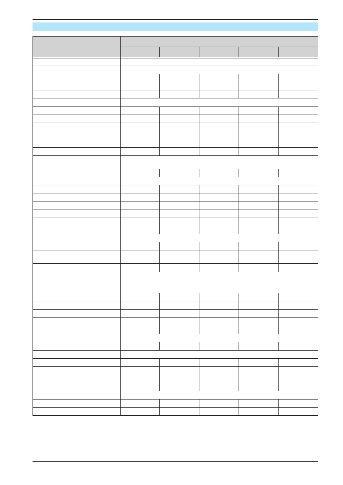
Model 400 V
5 kW / 6.6 kW / 10 kW
AC Input
Voltage (L-L) 340...460 V AC, 45 - 65 Hz
Input connection 2ph,PE 3ph,PE 3ph,PE 3ph,PE 3ph,PE
Leak current < 3.5 mA < 3.5 mA < 3.5 mA < 3.5 mA < 3.5 mA
Power factor > 0.99 > 0.99 > 0.99 > 0.99 > 0.99
DC Output
Max. output voltage U
Max. output current I
Max. output power P
Overvoltage protection range 0...825 V 0...44 V 0...44 V 0...88 V 0...220 V
Overcurrent protection range 0...22 A 0...374 A 0...561 A 0...374 A 0...154 A
Overpower protection range 0…5.5 kW 0…7.26 kW 0…11 kW 0…11 kW 0…11 kW
Temperature coecient for set
values Δ/K
Output capacitance (approx.) 100 μF 16900 μF 25380 μF 16900 μF 5040 μF
Voltage regulation
Adjustment range 0...765 V 0...40.8 V 0...40.8 V 0...81.6 V 0...204 V
Accuracy
(1
(at 23±5°C / 73±9°F)) < 0.1% U
Line regulation at ±10% ΔU
Load regulation at 0...100% load < 0.05% U
Rise time 10...90% Max. 30 ms Max. 30 ms Max. 30 ms Max. 30 ms Max. 30 ms
Settling time after load step < 1.5 ms < 1.5 ms < 1.5 ms < 1.5 ms < 1.5 ms
Display: Resolution See section „1.9.6.4. Resolution of the displayed values“
Display: Accuracy
(2
Ripple
Remote sensing compensation Max. 5% U
Fall time at no load after switching
DC output o
Current regulation
Adjustment range 0...20.4 A 0...346.8 A 0...520.2 A 0...346.8 A 0...142.8 A
Accuracy
(1
(at 23±5°C / 73±9°F)) < 0.2% I
Line regulation at ±10% ΔU
Load regulation at 0...100% ΔU
(2
Ripple
Display: Resolution See section „1.9.6.4. Resolution of the displayed values“
Display: Accuracy
Power regulation
Adjustment range 0…5.1 kW 0…6.72 kW 0…10.2 kW 0…10.2 kW 0…10.2 kW
Accuracy
(1
(at 23±5°C / 73±9°F)) < 1% P
Line regulation at ±10% ΔU
Load reg. at 10-90% ΔU
Display: Resolution See section „1.9.6.4. Resolution of the displayed values“
Display: Accuracy
Eciency
(3
Max
Max
Max
AC
(4
AC
(4
AC
* ΔI
OUT
(4
PS 9750-20 PS 9040-340 PS 9040-510 PS 9080-340 PS 9200-140
750 V 40 V 40 V 80 V 200 V
20 A 340 A 510 A 340 A 140 A
5 kW 6.6 kW 10 kW 10 kW 10 kW
Voltage / current: 100 ppm
Max
Max
RMS
Max
< 0.1% U
Max
< 0.02% U
< 0.05% U
≤ 0.2% U
Max
< 320 mVPP
< 25 mV
RMS
Max. 5% U
Max
< 0.02% U
≤ 0.2% U
Max
< 800 mVPP
< 200 mV
Down from
100% to <60 V:
- -
less than 10 s
Max
Max
Max
Max
< 0.2% I
Max
< 0.05% I
< 0.15% I
< 160 mA
≤ 0.2% I
< 1% P
Max
Max
< 0.05% P
< 0.75% P
≤ 0.7% P
Max
OUT
OUT
Max
< 0.05% I
< 0.15% I
< 16 mA
≤ 0.2% I
RMS
Max
Max
< 0.05% P
< 0.75% P
≤ 0.8% P
Max
≈ 94% ≈ 93% ≈ 93% ≈ 93% ≈ 95%
Max
Max
Max
Max
Max
RMS
Max
Max
< 0.1% U
Max
< 0.02% U
< 0.05% U
≤ 0.2% U
Max
< 320 mVPP
< 25 mV
RMS
Max. 5% U
< 0.2% I
< 0.05% I
< 0.15% I
< 120 mA
≤ 0.2% I
< 1% P
Max
Max
Max
RMS
Max
Max
< 0.05% P
< 0.75% P
≤ 0.7% P
Max
< 0.1% U
< 0.02% U
Max
< 0.05% U
Max
≤ 0.2% U
< 320 mVPP
< 25 mV
Max. 5% U
Max
Down from
100% to <60 V:
less than 10 s
< 0.2% I
< 0.05% I
< 0.15% I
< 160 mA
≤ 0.2% I
< 1% P
< 0.05% P
Max
< 0.75% P
Max
≤ 0.8% P
Max
RMS
Max
Max
Max
Max
Max
Max
Max
Max
Max
Max
RMS
Max
Max
< 0.1% U
< 0.02% U
< 0.05% U
≤ 0.2% U
< 300 mVPP
< 40 mV
Max. 5% U
Down from
100% to <60 V:
less than 10 s
< 0.2% I
< 0.05% I
< 0.15% I
< 44 mA
≤ 0.2% I
< 1% P
< 0.05% P
< 0.75% P
≤ 0.85% P
Max
Max
Max
Max
RMS
Max
Max
Max
Max
RMS
Max
Max
Max
Max
Max
(1 Related to the nominal values, the accuracy denes the maximum deviation between an adjusted values and the true (actual) value.
Example: a 80 V model has min. 0.1% voltage accuracy, that is 80 mV. When adjusting the voltage to 5 V, the actual value is allowed to dier max. 80 mV, which
means it might be between 4.92 V and 5.08 V.
(2 RMS value: LF 0...300 kHz, PP value: HF 0...20MHz
(3 Typical value at 100% output voltage and 100% power
(4 The display error adds to the error of the related actual value on the DC output
EA Elektro-Automatik GmbH
Helmholtzstr. 31-37 • 41747 Viersen
Germany
Fon: +49 2162 / 3785-0
Fax: +49 2162 / 16230
www.elektroautomatik.de
ea1974@elektroautomatik.de
Page 12

PS 9000 3U Series
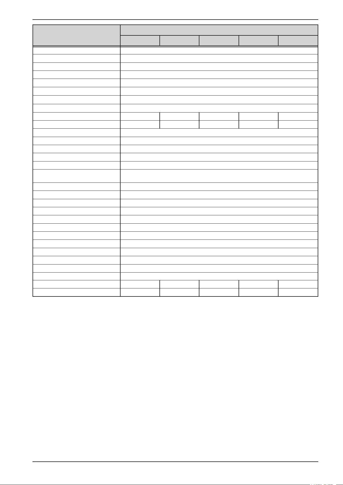
Model 400 V
5 kW / 6.6 kW / 10 kW
Analog interface
Set value inputs U, I, P
Actual value outputs U, I
Control signals DC on/o, remote control on/o
Status signals CV, OVP, OT, OCP, OPP, PF, DC on/o
Galvanic isolation to the device Max. 725 V DC
Sample rate of inputs 500 Hz
Insulation Allowed oat (potential shift) on the DC output:
Negative terminal to PE Max. ±725 V DC ±400 V DC ±400 V DC ±400 V DC ±400 V DC
Positive terminal to PE Max. ±1000 V DC ±400 V DC ±400 V DC ±400 V DC ±600 V DC
Miscellaneous
Cooling Temperature controlled fans, front inlet, rear exhaust
Ambient temperature 0..50°C (32...122°F)
Storage temperature -20...70°C (-4...158°F)
Humidity < 80%, not condensing
Standards
Overvoltage category 2
Protection class 1
Pollution degree 2
Operational altitude <2000 m (1,242 mi)
Digital interfaces
Featured 1x USB-B, 1x Ethernet (2, 1x GPIB (optional with option 3W)
Galvanic isolation from device Max. 725 V DC
Connectors
Rear side Share Bus, DC output, AC input, remote sensing, analog interface, USB-B, Ethernet
Dimensions
Enclosure (WxHxD) 19“ x 3 U x 609 mm (24”)
Total (WxHxD) 483 x 133 x 714 mm (19” x 5,2” x 28,1”)
Weight
Article number
(1
(3
PS 9750-20 PS 9040-340 PS 9040-510 PS 9080-340 PS 9200-140
EN 61010-1:2010
EMC TÜV approved acc. IEC 61000-6-2:2005 and IEC 61000-6-3:2006 Class B
≈17 kg (37.5 lb) ≈24 kg (52.9 lb) ≈30 kg (66.1 lb) ≈24 kg (52.9 lb) ≈24 kg (52.9 lb)
06230255 06230256 06230263 06230257 06230258
(1 For technical specications of the analog interface see „3.5.4.4 Analog interface specication“ on page 58
(2 Only in the standard version
(3 Article number of the standard EU version, devices with options will have a dierent number
EA Elektro-Automatik GmbH
Helmholtzstr. 31-37 • 41747 Viersen
Germany
Fon: +49 2162 / 3785-0
Fax: +49 2162 / 16230
www.elektroautomatik.de
ea1974@elektroautomatik.de
Page 13
PS 9000 3U Series
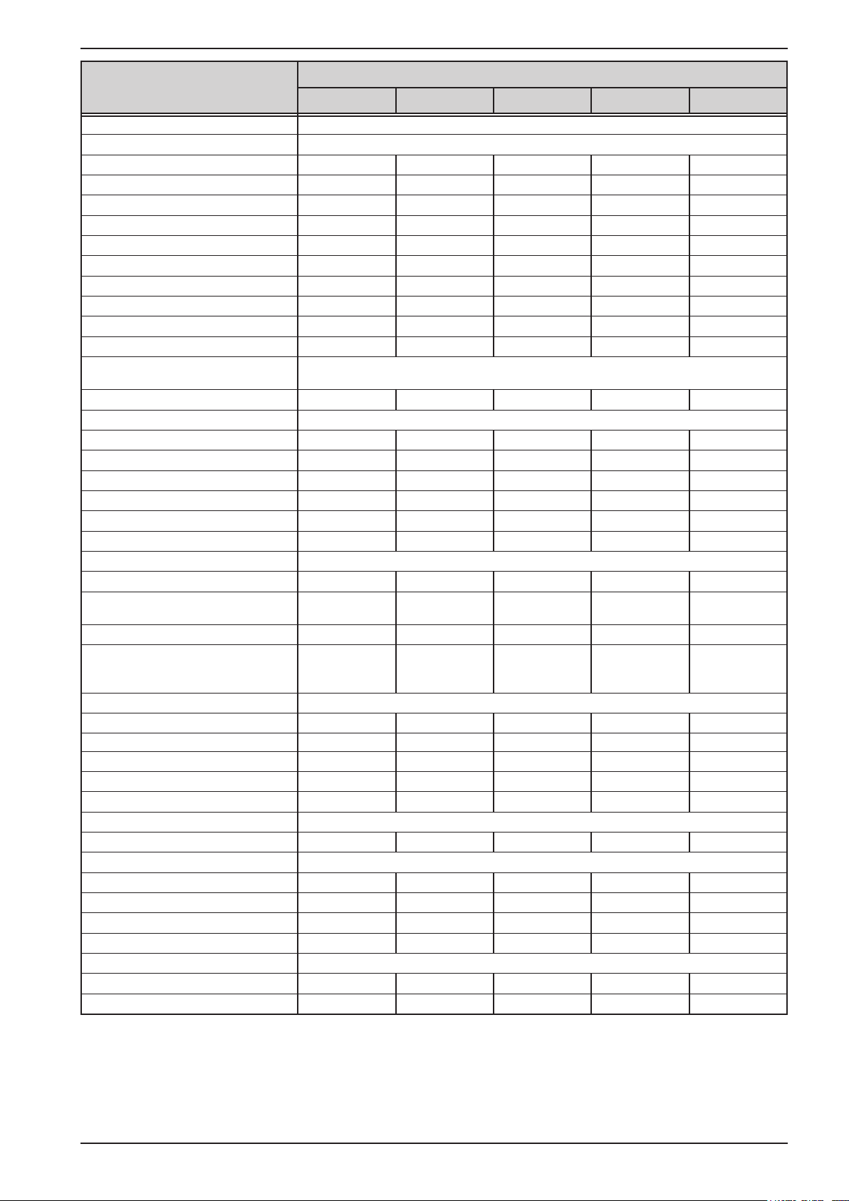
Model 400 V
10 kW / 15 kW
AC Input
Voltage (L-L) 340...460 V AC, 45 - 65 Hz
Input connection 3ph,PE
Leak current < 3.5 mA
Power factor > 0.99
DC Output
Max. output voltage U
Max. output current I
Max. output power P
Overvoltage protection range 0...396 V 0...550 V 0...825 V 0...1100 V 0...88 V
Overcurrent protection range 0...88 A 0...66 A 0...44 A 0...33 A 0...561 A
Overpower protection range 0…11 kW 0…11 kW 0…11 kW 0…11 kW 0…16.5 kW
Temperature coecient for set
values Δ/K
Output capacitance (approx.) 800 μF 500 μF 210 μF 127 μF 25380 μF
Voltage regulation
Adjustment range 0...367.2 V 0...510 V 0...765 V 0...1020 V 0...81.6 V
Accuracy
(1
(at 23±5°C / 73±9°F)) < 0.1% U
Line regulation at ±10% ΔU
Load regulation at 0...100% load < 0.05% U
Rise time 10...90% Max. 30 ms Max. 30 ms Max. 30 ms Max. 30 ms Max. 30 ms
Settling time after load step < 1.5 ms < 1.5 ms < 1.5 ms < 1.5 ms < 2 ms
Display: Resolution See section „1.9.6.4. Resolution of the displayed values“
Display: Accuracy
(2
Ripple
Remote sensing compensation Max. 5% U
Fall time at no load after switching
DC output o
Current regulation
Adjustment range 0...81.6 A 0...61.2 A 0...40.8 A 0...30.6 A 0...520.2 A
Accuracy
(1
(at 23±5°C / 73±9°F)) < 0.2% I
Line regulation at ±10% ΔU
Load regulation at 0...100% ΔU
(2
Ripple
Display: Resolution See section „1.9.6.4. Resolution of the displayed values“
Display: Accuracy
Power regulation
Adjustment range 0…10.2 kW 0…10.2 kW 0…10.2 kW 0…10.2 kW 0…15.3 kW
Accuracy
(1
(at 23±5°C / 73±9°F)) < 1% P
Line regulation at ±10% ΔU
Load reg. at 10-90% ΔU
Display: Resolution See section „1.9.6.4. Resolution of the displayed values“
Display: Accuracy
Eciency
(3
Max
Max
Max
AC
(4
AC
(4
AC
* ΔI
OUT
(4
PS 9360-80 PS 9500-60 PS 9750-40 PS 91000-30 PS 9080-510
360 V 500 V 750 V 1000 V 80 V
80 A 60 A 40 A 30 A 510 A
10 kW 10 kW 10 kW 10 kW 15 kW
Voltage / current: 100 ppm
Max
Max
Max
< 0.1% U
Max
< 0.02% U
< 0.05% U
≤ 0.2% U
Max
< 350 mVPP
< 70 mV
RMS
Max. 5% U
Max
< 0.02% U
≤ 0.2% U
Max
< 550 mVPP
< 65 mV
RMS
Down from 100% to <60 V: less than 10 s
Max
Max
RMS
Max
Max
< 0.2% I
Max
< 0.05% I
< 0.15% I
< 32 mA
≤ 0.2% I
< 1% P
RMS
Max
Max
< 0.05% P
< 0.75% P
≤ 0.85% P
OUT
OUT
Max
< 0.05% I
< 0.15% I
< 10.4 mA
≤ 0.2% I
Max
Max
< 0.05% P
< 0.75% P
≤ 0.8% P
Max
≈ 93% ≈ 95% ≈ 94% ≈ 95% ≈ 93%
Max
Max
Max
Max
Max
Max
Max
Max
< 0.1% U
Max
< 0.02% U
< 0.05% U
≤ 0.2% U
Max
< 800 mVPP
< 200 mV
RMS
Max. 5% U
< 0.2% I
< 0.05% I
< 0.15% I
< 32 mA
≤ 0.2% I
< 1% P
Max
Max
Max
RMS
Max
Max
< 0.05% P
< 0.75% P
≤ 0.85% P
Max
Max
Max
Max
Max
Max
< 0.1% U
< 0.02% U
< 0.05% U
≤ 0.2% U
Max
Max
Max
Max
< 1600 mVPP
< 350 mV
Max. 5% U
< 0.2% I
< 0.05% I
< 0.15% I
< 22 mA
≤ 0.2% I
< 1% P
< 0.05% P
< 0.75% P
≤ 0.85% P
RMS
Max
Max
Max
Max
RMS
Max
Max
Max
Max
Max
< 0.1% U
< 0.02% U
< 0.05% U
≤ 0.2% U
< 320 mVPP
< 25 mV
Max. 5% U
< 0.2% I
< 0.05% I
< 0.15% I
< 240 mA
≤ 0.2% I
< 1% P
< 0.05% P
< 0.75% P
≤ 0.8% P
Max
Max
Max
Max
RMS
Max
Max
Max
Max
RMS
Max
Max
Max
Max
Max
(1 Related to the nominal values, the accuracy denes the maximum deviation between an adjusted values and the true (actual) value.
Example: a 80 V model has min. 0.1% voltage accuracy, that is 80 mV. When adjusting the voltage to 5 V, the actual value is allowed to dier max. 80 mV, which
means it might be between 4.92 V and 5.08 V.
(2 RMS value: LF 0...300 kHz, PP value: HF 0...20MHz
(3 Typical value at 100% output voltage and 100% power
(4 The display error adds to the error of the related actual value on the DC output
EA Elektro-Automatik GmbH
Helmholtzstr. 31-37 • 41747 Viersen
Germany
Fon: +49 2162 / 3785-0
Fax: +49 2162 / 16230
www.elektroautomatik.de
ea1974@elektroautomatik.de
Page 14

PS 9000 3U Series
Model 400 V
10 kW / 15 kW
Analog interface
Set value inputs U, I, P
Actual value outputs U, I
Control signals DC on/o, remote control on/o
Status signals CV, OVP, OT, OCP, OPP, PF, DC on/o
Galvanic isolation to the device Max. 725 V DC
Sample rate of inputs 500 Hz
Insulation Allowed oat (potential shift) on the DC output:
Negative terminal to PE Max. ±400 V DC ±725 V DC ±725 V DC ±725 V DC ±400 V DC
Positive terminal to PE Max. ±600 V DC ±1000 V DC ±1000 V DC ±1000 V DC ±400 V DC
Miscellaneous
Cooling Temperature controlled fans, front inlet, rear exhaust
Ambient temperature 0..50°C (32...122°F)
Storage temperature -20...70°C (-4...158°F)
Humidity < 80%, not condensing
Standards
Overvoltage category 2
Protection class 1
Pollution degree 2
Operational altitude <2000 m (1,242 mi)
Digital interfaces
Featured 1x USB-B, 1x Ethernet (2, 1x GPIB (optional with option 3W)
Galvanic isolation from device Max. 725 V DC
Connectors
Rear side Share Bus, DC output, AC input, remote sensing, analog interface, USB-B, Ethernet
Dimensions
Enclosure (WxHxD) 19“ x 3 U x 609 mm (24”)
Total (WxHxD) 483 x 133 x 714 mm (19” x 5,2” x 28,1”)
Weight
Article number
(1
(3
PS 9360-80 PS 9500-60 PS 9750-40 PS 91000-30 PS 9080-510
EN 61010-1:2010
EMC TÜV approved acc. IEC 61000-6-2:2005 and IEC 61000-6-3:2006 Class B
≈24 kg (52.9 lb) ≈24 kg (52.9 lb) ≈24 kg (52.9 lb) ≈24 kg (52.9 lb) ≈30 kg (66.1 lb)
06230259 06230260 06230261 06230262 06230264
(1 For technical specications of the analog interface see „3.5.4.4 Analog interface specication“ on page 58
(2 Only in the standard version
(3 Article number of the standard EU version, devices with options will have a dierent number
EA Elektro-Automatik GmbH
Helmholtzstr. 31-37 • 41747 Viersen
Germany
Fon: +49 2162 / 3785-0
Fax: +49 2162 / 16230
www.elektroautomatik.de
ea1974@elektroautomatik.de
Page 15

PS 9000 3U Series
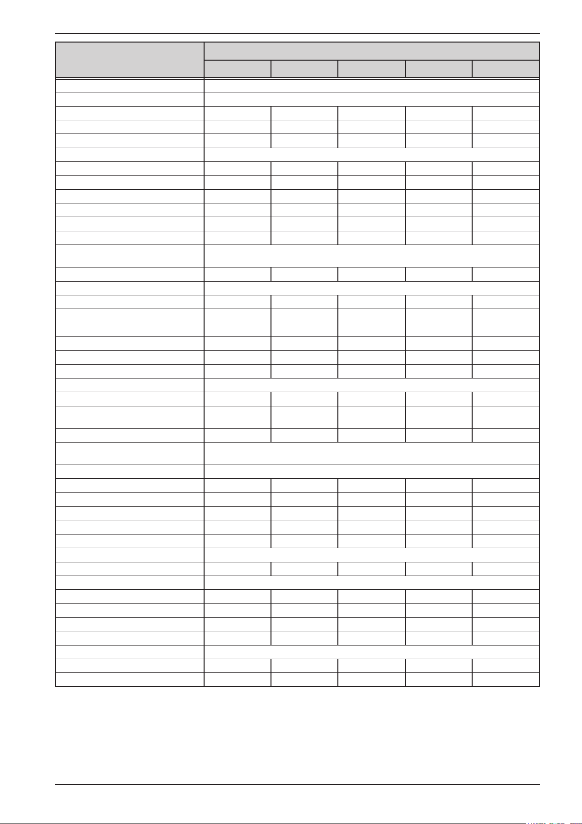
Model 400 V
15 kW
AC Input
Voltage (L-L) 340...460 V AC, 45 - 65 Hz
Input connection 3ph,PE
Leak current < 3.5 mA
Power factor > 0.99
DC Output
Max. output voltage U
Max. output current I
Max. output power P
Overvoltage protection range 0...220 V 0...396 V 0...550 V 0...825 V 0...1650 V
Overcurrent protection range 0...231 A 0...132 A 0...99 A 0...66 A 0...33 A
Overpower protection range 0…16.5 kW 0…16.5 kW 0…16.5 kW 0…16.5 kW 0…16.5 kW
Temperature coecient for set
values Δ/K
Output capacitance (approx.) 7560 μF 1200 μF 760 μF 310 μF 84 μF
Voltage regulation
Adjustment range 0...204 V 0...367.2 V 0...510 V 0...765 V 0...1530 V
Accuracy
(1
(at 23±5°C / 73±9°F)) < 0.1% U
Line regulation at ±10% ΔU
Load regulation at 0...100% load < 0.05% U
Rise time 10...90% Max. 30 ms Max. 30 ms Max. 30 ms Max. 30 ms Max. 30 ms
Settling time after load step < 2 ms < 2 ms < 2 ms < 2 ms < 2 ms
Display: Resolution See section „1.9.6.4. Resolution of the displayed values“
Display: Accuracy
(2
Ripple
Remote sensing compensation Max. 5% U
Fall time at no load after switching
DC output o
Current regulation
Adjustment range 0...214.2 A 0...122.4 A 0...91.8 A 0...61.2 A 0...30.6 A
Accuracy
(1
(at 23±5°C / 73±9°F)) < 0.2% I
Line regulation at ±10% ΔU
Load regulation at 0...100% ΔU
(2
Ripple
Display: Resolution See section „1.9.6.4. Resolution of the displayed values“
Display: Accuracy
Power regulation
Adjustment range 0…15.3 kW 0…15.3 kW 0…15.3 kW 0…15.3 kW 0…15.3 kW
Accuracy
(1
(at 23±5°C / 73±9°F)) < 1% P
Line regulation at ±10% ΔU
Load reg. at 10-90% ΔU
Display: Resolution See section „1.9.6.4. Resolution of the displayed values“
Display: Accuracy
Eciency
(3
Max
Max
Max
AC
(4
AC
(4
AC
* ΔI
OUT
(4
PS 9200-210 PS 9360-120 PS 9500-90 PS 9750-60 PS 91500-30
200 V 360 V 500 V 750 V 1500 V
210 A 120 A 90 A 60 A 30 A
15 kW 15 kW 15 kW 15 kW 15 kW
Voltage / current: 100 ppm
Max
Max
Max
< 0.1% U
Max
< 0.02% U
< 0.05% U
≤ 0.2% U
Max
< 550 mVPP
< 65 mV
RMS
Max. 5% U
Max
< 0.02% U
≤ 0.2% U
Max
< 300 mVPP
< 40 mV
RMS
Down from 100% to <60 V: less than 10 s
Max
Max
Max
Max
< 0.2% I
Max
< 0.05% I
< 0.15% I
< 15.6 mA
≤ 0.2% I
< 1% P
Max
Max
< 0.05% P
< 0.75% P
≤ 0.85% P
OUT
OUT
Max
< 0.05% I
< 0.15% I
< 66 mA
≤ 0.2% I
RMS
Max
Max
< 0.05% P
< 0.75% P
≤ 0.8% P
Max
≈ 95% ≈ 94% ≈ 95% ≈ 94% ≈ 95%
Max
Max
Max
Max
Max
RMS
Max
Max
Max
< 0.1% U
Max
< 0.02% U
< 0.05% U
≤ 0.2% U
Max
< 350 mVPP
< 70 mV
RMS
Max. 5% U
< 0.2% I
< 0.05% I
< 0.15% I
< 48 mA
≤ 0.2% I
< 1% P
Max
Max
Max
RMS
Max
Max
< 0.05% P
< 0.75% P
≤ 0.85% P
Max
Max
Max
Max
Max
Max
< 0.1% U
Max
< 0.02% U
< 0.05% U
≤ 0.2% U
Max
< 800 mVPP
< 200 mV
RMS
Max. 5% U
< 0.2% I
< 0.05% I
< 0.15% I
< 48 mA
≤ 0.2% I
< 1% P
Max
Max
Max
RMS
Max
Max
< 0.05% P
< 0.75% P
≤ 0.85% P
Max
Max
Max
Max
Max
Max
< 0.1% U
< 0.02% U
< 0.05% U
≤ 0.2% U
< 2400 mVPP
< 400 mV
Max. 5% U
< 0.2% I
< 0.05% I
< 0.15% I
< 26 mA
≤ 0.2% I
< 1% P
< 0.05% P
< 0.75% P
≤ 0.85% P
Max
Max
Max
Max
RMS
Max
Max
Max
Max
RMS
Max
Max
Max
Max
Max
(1 Related to the nominal values, the accuracy denes the maximum deviation between an adjusted values and the true (actual) value.
Example: a 80 V model has min. 0.1% voltage accuracy, that is 80 mV. When adjusting the voltage to 5 V, the actual value is allowed to dier max. 80 mV, which
means it might be between 4.92 V and 5.08 V.
(2 RMS value: LF 0...300 kHz, PP value: HF 0...20MHz
(3 Typical value at 100% output voltage and 100% power
(4 The display error adds to the error of the related actual value on the DC output
EA Elektro-Automatik GmbH
Helmholtzstr. 31-37 • 41747 Viersen
Germany
Fon: +49 2162 / 3785-0
Fax: +49 2162 / 16230
www.elektroautomatik.de
ea1974@elektroautomatik.de
Page 16

PS 9000 3U Series
Model 400 V
15 kW
Analog interface
Set value inputs U, I, P
Actual value outputs U, I
Control signals DC on/o, remote control on/o
Status signals CV, OVP, OT, OCP, OPP, PF, DC on/o
Galvanic isolation to the device Max. 725 V DC
Sample rate of inputs 500 Hz
Insulation Allowed oat (potential shift) on the DC output:
Negative terminal to PE Max. ±400 V DC ±400 V DC ±725 V DC ±725 V DC ±725 V DC
Positive terminal to PE Max. ±600 V DC ±600 V DC ±1000 V DC ±1000 V DC ±1800 V DC
Miscellaneous
Cooling Temperature controlled fans, front inlet, rear exhaust
Ambient temperature 0..50°C (32...122°F)
Storage temperature -20...70°C (-4...158°F)
Humidity < 80%, not condensing
Standards
Overvoltage category 2
Protection class 1
Pollution degree 2
Operational altitude <2000 m (1,242 mi)
Digital interfaces
Featured 1x USB-B, 1x Ethernet (2, 1x GPIB (optional with option 3W)
Galvanic isolation from device Max. 725 V DC
Connectors
Rear side Share Bus, DC output, AC input, remote sensing, analog interface, USB-B, Ethernet
Dimensions
Enclosure (WxHxD) 19“ x 3 U x 609 mm (24”)
Total (WxHxD) 483 x 133 x 714 mm (19” x 5,2” x 28,1”)
Weight
Article number
(1
(3
PS 9200-210 PS 9360-120 PS 9500-90 PS 9750-60 PS 91500-30
EN 61010-1:2010
EMC TÜV approved acc. IEC 61000-6-2:2005 and IEC 61000-6-3:2006 Class B
≈30 kg (66.1 lb) ≈30 kg (66.1 lb) ≈30 kg (66.1 lb) ≈30 kg (66.1 lb) ≈30 kg (66.1 lb)
06230265 06230266 06230267 06230268 06230269
(1 For technical specications of the analog interface see „3.5.4.4 Analog interface specication“ on page 58
(2 Only in the standard version
(3 Article number of the standard EU version, devices with options will have a dierent number
EA Elektro-Automatik GmbH
Helmholtzstr. 31-37 • 41747 Viersen
Germany
Fon: +49 2162 / 3785-0
Fax: +49 2162 / 16230
www.elektroautomatik.de
ea1974@elektroautomatik.de
Page 17
PS 9000 3U Series
1.8.4 Specic technical data (208 V AC models)
Model 208 V
5 kW
AC Input
Voltage (L-L) 208 V, ± 10%, 45 - 65 Hz
Input connection 2ph,PE 2ph,PE 2ph,PE 2ph,PE 2ph,PE
Leak current < 3.5 mA < 3.5 mA < 3.5 mA < 3.5 mA < 3.5 mA
Power factor > 0.99 > 0.99 > 0.99 > 0.99 > 0.99
DC Output
Max. output voltage U
Max. output current I
Max. output power P
Overvoltage protection range 0...88 V 0...220 V 0...396 V 0...550 V 0...825 V
Overcurrent protection range 0...187 A 0...77 A 0...44 A 0...33 A 0...22 A
Overpower protection range 0…5.5 kW 0…5.5 kW 0…5.5 kW 0…5.5 kW 0…5.5 kW
Temperature coecient for set
values Δ/K
Output capacitance (approx.) 8500 μF 2500 μF 400 μF 250 μF 100 μF
Voltage regulation
Adjustment range 0...81.6 V 0...204 V 0...367.2 V 0...510 V 0...765 V
Accuracy
(1
(at 23±5°C / 73±9°F)) < 0.1% U
Line regulation at ±10% ΔU
Load regulation at 0...100% load < 0.05% U
Rise time 10...90% Max. 30 ms Max. 30 ms Max. 30 ms Max. 30 ms Max. 30 ms
Settling time after load step < 1.5 ms < 1.5 ms < 1.5 ms < 1.5 ms < 1.5 ms
Display: Resolution See section „1.9.6.4. Resolution of the displayed values“
Display: Accuracy
(2
Ripple
Remote sensing compensation Max. 5% U
Fall time at no load after switching
DC output o
Current regulation
Adjustment range 0...173.4 A 0...71.4 A 0...40.8 A 0...30.6 A 0...20.4 A
Accuracy
(1
(at 23±5°C / 73±9°F)) < 0.2% I
Line regulation at ±10% ΔU
Load regulation at 0...100% ΔU
(2
Ripple
Display: Resolution See section „1.9.6.4. Resolution of the displayed values“
Display: Accuracy
Power regulation
Adjustment range 0…5.1 kW 0…5.1 kW 0…5.1 kW 0…5.1 kW 0…5.1 kW
Accuracy
(1
(at 23±5°C / 73±9°F)) < 1% P
Line regulation at ±10% ΔU
Load reg. at 10-90% ΔU
Display: Resolution See section „1.9.6.4. Resolution of the displayed values“
Display: Accuracy
Eciency
(3
Max
Max
Max
AC
(4
AC
(4
AC
* ΔI
OUT
(4
PS 9080-170 PS 9200-70 PS 9360-40 PS 9500-30 PS 9750-20
80 V 200 V 360 V 500 V 750 V
170 A 70 A 40 A 30 A 20 A
5 kW 5 kW 5 kW 5 kW 5 kW
Voltage / current: 100 ppm
Max
Max
Max
< 0.1% U
Max
< 0.02% U
< 0.05% U
≤ 0.2% U
Max
< 300 mVPP
< 40 mV
RMS
Max. 5% U
Max
< 0.02% U
≤ 0.2% U
Max
< 200 mVPP
< 16 mV
RMS
Down from 100% to <60 V: less than 10 s
Max
Max
Max
Max
< 0.2% I
Max
< 0.05% I
< 0.15% I
< 22 mA
≤ 0.2% I
< 1% P
RMS
Max
Max
< 0.05% P
< 0.75% P
≤ 0.8% P
Max
OUT
OUT
Max
< 0.05% I
< 0.15% I
< 80 mA
≤ 0.2% I
RMS
Max
Max
< 0.05% P
< 0.75% P
≤ 0.8% P
Max
≈ 93% ≈ 95% ≈ 95% ≈ 95,5% ≈ 94%
Max
Max
Max
Max
Max
Max
Max
< 0.1% U
Max
< 0.02% U
< 0.05% U
≤ 0.2% U
Max
< 550 mVPP
< 65 mV
RMS
Max. 5% U
< 0.2% I
< 0.05% I
< 0.15% I
< 5.2 mA
≤ 0.2% I
< 1% P
Max
Max
Max
RMS
Max
Max
< 0.05% P
< 0.75% P
≤ 0.8% P
Max
Max
Max
Max
Max
Max
< 0.1% U
Max
< 0.02% U
< 0.05% U
≤ 0.2% U
Max
< 350 mVPP
< 70 mV
RMS
Max. 5% U
< 0.2% I
< 0.05% I
< 0.15% I
< 16 mA
≤ 0.2% I
< 1% P
Max
Max
Max
RMS
Max
Max
< 0.05% P
< 0.75% P
≤ 0.8% P
Max
Max
Max
Max
Max
Max
< 0.1% U
< 0.02% U
< 0.05% U
≤ 0.2% U
< 800 mVPP
< 200 mV
Max. 5% U
< 0.2% I
< 0.05% I
< 0.15% I
< 16 mA
≤ 0.2% I
< 1% P
< 0.05% P
< 0.75% P
≤ 0.8% P
Max
Max
Max
Max
RMS
Max
Max
Max
Max
RMS
Max
Max
Max
Max
Max
(1 Related to the nominal values, the accuracy denes the maximum deviation between an adjusted values and the true (actual) value.
Example: a 80 V model has min. 0.1% voltage accuracy, that is 80 mV. When adjusting the voltage to 5 V, the actual value is allowed to dier max. 80 mV, which
means it might be between 4.92 V and 5.08 V.
(2 RMS value: LF 0...300 kHz, PP value: HF 0...20MHz
(3 Typical value at 100% output voltage and 100% power
(4 The display error adds to the error of the related actual value on the DC output
EA Elektro-Automatik GmbH
Helmholtzstr. 31-37 • 41747 Viersen
Germany
Fon: +49 2162 / 3785-0
Fax: +49 2162 / 16230
www.elektroautomatik.de
ea1974@elektroautomatik.de
Page 18

PS 9000 3U Series
Model 208 V
5 kW
Analog interface
Set value inputs U, I, P
Actual value outputs U, I
Control signals DC on/o, remote control on/o
Status signals CV, OVP, OT, OCP, OPP, PF, DC on/o
Galvanic isolation to the device Max. 725 V DC
Sample rate of inputs 500 Hz
Insulation Allowed oat (potential shift) on the DC output:
Negative terminal to PE Max. ±400 V DC ±400 V DC ±400 V DC ±725 V DC ±725 V DC
Positive terminal to PE Max. +400 V DC +600 V DC +600 V DC +1000 V DC +1000 V DC
Miscellaneous
Cooling Temperature controlled fans, front inlet, rear exhaust
Ambient temperature 0..50°C (32...122°F)
Storage temperature -20...70°C (-4...158°F)
Humidity < 80%, not condensing
Standards
Overvoltage category 2
Protection class 1
Pollution degree 2
Operational altitude <2000 m (1,242 mi)
Digital interfaces
Featured 1x USB-B, 1x Ethernet (2, 1x GPIB (optional with option 3W)
Galvanic isolation from device Max. 725 V DC
Connectors
Rear side Share Bus, DC output, AC input, remote sensing, analog interface, USB-B, Ethernet
Dimensions
Enclosure (WxHxD) 19“ x 3U x 682 mm (26.8”)
Total (WxHxD) 483 x 133 x 787 mm (19” x 5.2” x 31”)
Weight
Article number
(1
(3
PS 9080-170 PS 9200-70 PS 9360-40 PS 9500-30 PS 9750-20
EN 61010-1:2010
EMC TÜV approved acc. IEC 61000-6-2:2005 and IEC 61000-6-3:2006 Class B
≈17 kg (37.5 lb) ≈17 kg (37.5 lb) ≈17 kg (37.5 lb) ≈17 kg (37.5 lb) ≈17 kg (37.5 lb)
06238251 06238252 06238253 06238254 06238255
(1 For technical specications of the analog interface see „3.5.4.4 Analog interface specication“ on page 58
(2 Only in the standard version
(3 Article number of the standard US version, devices with options will have a dierent number
EA Elektro-Automatik GmbH
Helmholtzstr. 31-37 • 41747 Viersen
Germany
Fon: +49 2162 / 3785-0
Fax: +49 2162 / 16230
www.elektroautomatik.de
ea1974@elektroautomatik.de
Page 19

PS 9000 3U Series
Model 208 V
10 kW
AC Input
Voltage (L-L) 208 V, ± 10%, 45 - 65 Hz
Input connection 3ph,PE 3ph,PE 3ph,PE 3ph,PE 3ph,PE
Leak current < 3.5 mA < 3.5 mA < 3.5 mA < 3.5 mA < 3.5 mA
Power factor > 0.99 > 0.99 > 0.99 > 0.99 > 0.99
DC Output
Max. output voltage U
Max. output current I
Max. output power P
Overvoltage protection range 0...88 V 0...220 V 0...396 V 0...550 V 0...825 V
Overcurrent protection range 0...374 A 0...154 A 0...88 A 0...66 A 0...44 A
Overpower protection range 0…11 kW 0…11 kW 0…11 kW 0…11 kW 0…11 kW
Temperature coecient for set
values Δ/K
Output capacitance (approx.) 16900 μF 5040 μF 800 μF 500 μF 210 μF
Voltage regulation
Adjustment range 0...81.6 V 0...204 V 0...367.2 V 0...510 V 0...765 V
Accuracy
(1
(at 23±5°C / 73±9°F)) < 0.1% U
Line regulation at ±10% ΔU
Load regulation at 0...100% load < 0.05% U
Rise time 10...90% Max. 30 ms Max. 30 ms Max. 30 ms Max. 30 ms Max. 30 ms
Settling time after load step < 1.5 ms < 1.5 ms < 1.5 ms < 1.5 ms < 1.5 ms
Display: Resolution See section „1.9.6.4. Resolution of the displayed values“
Display: Accuracy
(2
Ripple
Remote sensing compensation Max. 5% U
Fall time at no load after switching
DC output o
Current regulation
Adjustment range 0...346.8 A 0...142.8 A 0...81.6 A 0...61.2 A 0...40.8 A
Accuracy
(1
(at 23±5°C / 73±9°F)) < 0.2% I
Line regulation at ±10% ΔU
Load regulation at 0...100% ΔU
(2
Ripple
Display: Resolution See section „1.9.6.4. Resolution of the displayed values“
Display: Accuracy
Power regulation
Adjustment range 0…10.2 kW 0…10.2 kW 0…10.2 kW 0…10.2 kW 0…10.2 kW
Accuracy
(1
(at 23±5°C / 73±9°F)) < 1% P
Line regulation at ±10% ΔU
Load reg. at 10-90% ΔU
Display: Resolution See section „1.9.6.4. Resolution of the displayed values“
Display: Accuracy
Eciency
(3
Max
Max
Max
AC
(4
AC
(4
AC
* ΔI
OUT
(4
PS 9080-340 PS 9200-140 PS 9360-80 PS 9500-60 PS 9750-40
80 V 200 V 360 V 500 V 750 V
340 A 140 A 80 A 60 A 40 A
10 kW 10 kW 10 kW 10 kW 10 kW
Voltage / current: 100 ppm
Max
Max
Max
< 0.1% U
Max
< 0.02% U
< 0.05% U
≤ 0.2% U
Max
< 300 mVPP
< 40 mV
RMS
Max. 5% U
Max
< 0.02% U
≤ 0.2% U
Max
< 320 mVPP
< 25 mV
RMS
Down from 100% to <60 V: less than 10 s
Max
Max
RMS
Max
Max
< 0.2% I
Max
< 0.05% I
< 0.15% I
< 44 mA
≤ 0.2% I
< 1% P
RMS
Max
Max
< 0.05% P
< 0.75% P
≤ 0.85% P
OUT
OUT
Max
< 0.05% I
< 0.15% I
< 160 mA
≤ 0.2% I
Max
Max
< 0.05% P
< 0.75% P
≤ 0.8% P
Max
≈ 93% ≈ 95% ≈ 93% ≈ 95% ≈ 94%
Max
Max
Max
Max
Max
Max
Max
Max
< 0.1% U
Max
< 0.02% U
< 0.05% U
≤ 0.2% U
Max
< 550 mVPP
< 65 mV
RMS
Max. 5% U
< 0.2% I
< 0.05% I
< 0.15% I
Max
Max
Max
< 10.4 mA
≤ 0.2% I
< 1% P
Max
Max
< 0.05% P
< 0.75% P
≤ 0.8% P
Max
Max
Max
Max
RMS
Max
Max
< 0.1% U
Max
< 0.02% U
< 0.05% U
≤ 0.2% U
Max
< 350 mVPP
< 70 mV
RMS
Max. 5% U
< 0.2% I
< 0.05% I
< 0.15% I
< 32 mA
≤ 0.2% I
< 1% P
Max
Max
Max
RMS
Max
Max
< 0.05% P
< 0.75% P
≤ 0.85% P
Max
Max
Max
Max
Max
Max
< 0.1% U
< 0.02% U
< 0.05% U
≤ 0.2% U
< 800 mVPP
< 200 mV
Max. 5% U
< 0.2% I
< 0.05% I
< 0.15% I
< 32 mA
≤ 0.2% I
< 1% P
< 0.05% P
< 0.75% P
≤ 0.85% P
Max
Max
Max
Max
RMS
Max
Max
Max
Max
RMS
Max
Max
Max
Max
Max
(1 Related to the nominal values, the accuracy denes the maximum deviation between an adjusted values and the true (actual) value.
Example: a 80 V model has min. 0.1% voltage accuracy, that is 80 mV. When adjusting the voltage to 5 V, the actual value is allowed to dier max. 80 mV, which
means it might be between 4.92 V and 5.08 V.
(2 RMS value: LF 0...300 kHz, PP value: HF 0...20MHz
(3 Typical value at 100% output voltage and 100% power
(4 The display error adds to the error of the related actual value on the DC output
EA Elektro-Automatik GmbH
Helmholtzstr. 31-37 • 41747 Viersen
Germany
Fon: +49 2162 / 3785-0
Fax: +49 2162 / 16230
www.elektroautomatik.de
ea1974@elektroautomatik.de
Page 20
PS 9000 3U Series
Model 208 V
10 kW
Analog interface
Set value inputs U, I, P
Actual value outputs U, I
Control signals DC on/o, remote control on/o
Status signals CV, OVP, OT, OCP, OPP, PF, DC on/o
Galvanic isolation to the device Max. 725 V DC
Sample rate of inputs 500 Hz
Insulation Allowed oat (potential shift) on the DC output:
Negative terminal to PE Max. ±400 V DC ±400 V DC ±400 V DC ±725 V DC ±725 V DC
Positive terminal to PE Max. ±400 V DC +600 V DC +600 V DC +1000 V DC +1000 V DC
Miscellaneous
Cooling Temperature controlled fans, front inlet, rear exhaust
Ambient temperature 0..50°C (32...122°F)
Storage temperature -20...70°C (-4...158°F)
Humidity < 80%, not condensing
Standards
Overvoltage category 2
Protection class 1
Pollution degree 2
Operational altitude <2000 m (1,242 mi)
Digital interfaces
Featured 1x USB-B, 1x Ethernet (2, 1x GPIB (optional with option 3W)
Galvanic isolation from device Max. 725 V DC
Connectors
Rear side Share Bus, DC output, AC input, remote sensing, analog interface, USB-B, Ethernet
Dimensions
Enclosure (WxHxD) 19“ x 3U x 682 mm (26.8”)
Total (WxHxD) 483 x 133 x 787 mm (19” x 5.2” x 31”)
Weight
Article number
(1
(3
PS 9080-340 PS 9200-140 PS 9360-80 PS 9500-60 PS 9750-40
EN 61010-1:2010
EMC TÜV approved acc. IEC 61000-6-2:2005 and IEC 61000-6-3:2006 Class B
≈24 kg (52.9 lb) ≈24 kg (52.9 lb) ≈24 kg (52.9 lb) ≈24 kg (52.9 lb) ≈24 kg (52.9 lb)
06238257 06238258 06238259 06238260 06238261
(1 For technical specications of the analog interface see „3.5.4.4 Analog interface specication“ on page 58
(2 Only in the standard version
(3 Article number of the standard US version, devices with options will have a dierent number
EA Elektro-Automatik GmbH
Helmholtzstr. 31-37 • 41747 Viersen
Germany
Fon: +49 2162 / 3785-0
Fax: +49 2162 / 16230
www.elektroautomatik.de
ea1974@elektroautomatik.de
Page 21
PS 9000 3U Series
Model 208 V
10 kW / 15 kW
AC Input
Voltage (L-L) 208 V, ± 10%, 45 - 65 Hz
Input connection 3ph,PE 3ph,PE 3ph,PE 3ph,PE 3ph,PE
Leak current < 3.5 mA < 3.5 mA < 3.5 mA < 3.5 mA < 3.5 mA
Power factor > 0.99 > 0.99 > 0.99 > 0.99 > 0.99
DC Output
Max. output voltage U
Max. output current I
Max. output power P
Overvoltage protection range 0...1100 V 0...88 V 0...220 V 0...396 V 0...550 V
Overcurrent protection range 0...33 A 0...561 A 0...231 A 0...132 A 0...99 A
Overpower protection range 0…11 kW 0…16.5 kW 0…16.5 kW 0…16.5 kW 0…16.5 kW
Temperature coecient for set
values Δ/K
Output capacitance (approx.) 127 μF 25380 μF 7560 μF 1200 μF 760 μF
Voltage regulation
Adjustment range 0...1020 V 0...81.6 V 0...204 V 0...367.2 V 0...510 V
Accuracy
(1
(at 23±5°C / 73±9°F)) < 0.1% U
Line regulation at ±10% ΔU
Load regulation at 0...100% load < 0.05% U
Rise time 10...90% Max. 30 ms Max. 30 ms Max. 30 ms Max. 30 ms Max. 30 ms
Settling time after load step < 1.5 ms < 2 ms < 2 ms < 2 ms < 2 ms
Display: Resolution See section „1.9.6.4. Resolution of the displayed values“
Display: Accuracy
(2
Ripple
Remote sensing compensation Max. 5% U
Fall time at no load after switching
DC output o
Current regulation
Adjustment range 0...30.6 A 0...520.2 A 0...214.2 A 0...122.4 A 0...91.8 A
Accuracy
(1
(at 23±5°C / 73±9°F)) < 0.2% I
Line regulation at ±10% ΔU
Load regulation at 0...100% ΔU
(2
Ripple
Display: Resolution See section „1.9.6.4. Resolution of the displayed values“
Display: Accuracy
Power regulation
Adjustment range 0…10.2 kW 0…15.3 kW 0…15.3 kW 0…15.3 kW 0…15.3 kW
Accuracy
(1
(at 23±5°C / 73±9°F)) < 1% P
Line regulation at ±10% ΔU
Load reg. at 10-90% ΔU
Display: Resolution See section „1.9.6.4. Resolution of the displayed values“
Display: Accuracy
Eciency
(3
Max
Max
Max
AC
(4
AC
(4
AC
* ΔI
OUT
(4
PS 91000-30 PS 9080-510 PS 9200-210 PS 9360-120 PS 9500-90
1000 V 80 V 200 V 360 V 500 V
30 A 510 A 210 A 120 A 90 A
10 kW 15 kW 15 kW 15 kW 15 kW
Voltage / current: 100 ppm
Max
Max
RMS
Max
< 0.1% U
Max
< 0.02% U
< 0.05% U
≤ 0.2% U
Max
< 320 mVPP
< 25 mV
RMS
Max. 5% U
Max
< 0.02% U
≤ 0.2% U
Max
< 1600 mVPP
< 350 mV
Down from 100% to <60 V: less than 10 s
Max
Max
Max
Max
Max
< 0.2% I
Max
< 0.05% I
< 0.15% I
< 240 mA
≤ 0.2% I
< 1% P
Max
Max
< 0.05% P
< 0.75% P
≤ 0.8% P
Max
OUT
OUT
Max
< 0.05% I
< 0.15% I
< 22 mA
≤ 0.2% I
RMS
Max
Max
< 0.05% P
< 0.75% P
≤ 0.85% P
≈ 95% ≈ 93% ≈ 95% ≈ 94% ≈ 95%
Max
Max
Max
Max
Max
RMS
Max
Max
< 0.1% U
Max
< 0.02% U
< 0.05% U
≤ 0.2% U
Max
< 300 mVPP
< 40 mV
RMS
Max. 5% U
< 0.2% I
< 0.05% I
< 0.15% I
< 66 mA
≤ 0.2% I
< 1% P
Max
Max
Max
RMS
Max
Max
< 0.05% P
< 0.75% P
≤ 0.8% P
Max
Max
Max
Max
Max
Max
< 0.1% U
Max
< 0.02% U
< 0.05% U
≤ 0.2% U
Max
< 550 mVPP
< 65 mV
RMS
Max. 5% U
< 0.2% I
< 0.05% I
< 0.15% I
Max
Max
Max
< 15.6 mA
≤ 0.2% I
< 1% P
Max
Max
< 0.05% P
< 0.75% P
≤ 0.85% P
Max
Max
Max
RMS
Max
Max
Max
< 0.1% U
< 0.02% U
< 0.05% U
≤ 0.2% U
< 350 mVPP
< 70 mV
Max. 5% U
< 0.2% I
< 0.05% I
< 0.15% I
< 48 mA
≤ 0.2% I
< 1% P
< 0.05% P
< 0.75% P
≤ 0.85% P
Max
Max
Max
Max
RMS
Max
Max
Max
Max
RMS
Max
Max
Max
Max
Max
(1 Related to the nominal values, the accuracy denes the maximum deviation between an adjusted values and the true (actual) value.
Example: a 80 V model has min. 0.1% voltage accuracy, that is 80 mV. When adjusting the voltage to 5 V, the actual value is allowed to dier max. 80 mV, which
means it might be between 4.92 V and 5.08 V.
(2 RMS value: LF 0...300 kHz, PP value: HF 0...20MHz
(3 Typical value at 100% output voltage and 100% power
(4 The display error adds to the error of the related actual value on the DC output
EA Elektro-Automatik GmbH
Helmholtzstr. 31-37 • 41747 Viersen
Germany
Fon: +49 2162 / 3785-0
Fax: +49 2162 / 16230
www.elektroautomatik.de
ea1974@elektroautomatik.de
Page 22

PS 9000 3U Series
Model 208 V
10 kW / 15 kW
Analog interface
Set value inputs U, I, P
Actual value outputs U, I
Control signals DC on/o, remote control on/o
Status signals CV, OVP, OT, OCP, OPP, PF, DC on/o
Galvanic isolation to the device Max. 725 V DC
Sample rate of inputs 500 Hz
Insulation Allowed oat (potential shift) on the DC output:
Negative terminal to PE Max. ±725 V DC ±400 V DC ±400 V DC ±400 V DC ±725 V DC
Positive terminal to PE Max. +1000 V DC ±400 V DC +600 V DC +600 V DC +1000 V DC
Miscellaneous
Cooling Temperature controlled fans, front inlet, rear exhaust
Ambient temperature 0..50°C (32...122°F)
Storage temperature -20...70°C (-4...158°F)
Humidity < 80%, not condensing
Standards
Overvoltage category 2
Protection class 1
Pollution degree 2
Operational altitude <2000 m (1,242 mi)
Digital interfaces
Featured 1x USB-B, 1x Ethernet (2, 1x GPIB (optional with option 3W)
Galvanic isolation from device Max. 725 V DC
Connectors
Rear side Share Bus, DC output, AC input, remote sensing, analog interface, USB-B, Ethernet
Dimensions
Enclosure (WxHxD) 19“ x 3U x 682 mm (26.8”)
Total (WxHxD) 483 x 133 x 787 mm (19” x 5.2” x 31”)
Weight
Article number
(1
(3
PS 91000-30 PS 9080-510 PS 9200-210 PS 9360-120 PS 9500-90
EN 61010-1:2010
EMC TÜV approved acc. IEC 61000-6-2:2005 and IEC 61000-6-3:2006 Class B
≈24 kg (52.9 lb) ≈30 kg (66.1 lb) ≈30 kg (66.1 lb) ≈30 kg (66.1 lb) ≈30 kg (66.1 lb)
06238262 06238264 06238265 06238266 06238267
(1 For technical specications of the analog interface see „3.5.4.4 Analog interface specication“ on page 58
(2 Only in the standard version
(3 Article number of the standard US version, devices with options will have a dierent number
EA Elektro-Automatik GmbH
Helmholtzstr. 31-37 • 41747 Viersen
Germany
Fon: +49 2162 / 3785-0
Fax: +49 2162 / 16230
www.elektroautomatik.de
ea1974@elektroautomatik.de
Page 23

PS 9000 3U Series
Model 208 V
15 kW
AC Input
Voltage (L-L) 208 V, ± 10%, 45 - 65 Hz
Input connection 3ph,PE 3ph,PE 3ph,PE
Leak current < 3.5 mA < 3.5 mA < 3.5 mA
Power factor > 0.99 > 0.99 > 0.99
DC Output
Max. output voltage U
Max. output current I
Max. output power P
Overvoltage protection range 0...825 V 0...1100 V 0...1650 V
Overcurrent protection range 0...66 A 0...44 A 0...33 A
Overpower protection range 0…16.5 kW 0...16.5 kW 0…16.5 kW
Temperature coecient for set
values Δ/K
Output capacitance (approx.) 310 μF 133 μF 84 μF
Voltage regulation
Adjustment range 0...765 V 0...1020 V 0...1530 V
Accuracy
(1
(at 23±5°C / 73±9°F)) < 0.1% U
Line regulation at ±10% ΔU
Load regulation at 0...100% load < 0.05% U
Rise time 10...90% Max. 30 ms Max. 30 ms Max. 30 ms
Settling time after load step < 2 ms < 2 ms < 2 ms
Display: Resolution See section „1.9.6.4. Resolution of the displayed values“
Display: Accuracy
(2
Ripple
Remote sensing compensation Max. 5% U
Fall time at no load after switching
DC output o
Current regulation
Adjustment range 0...61.2 A 0...40.8 A 0...30.6 A
Accuracy
(1
(at 23±5°C / 73±9°F)) < 0.2% I
Line regulation at ±10% ΔU
Load regulation at 0...100% ΔU
(2
Ripple
Display: Resolution See section „1.9.6.4. Resolution of the displayed values“
Display: Accuracy
Power regulation
Adjustment range 0…15.3 kW 0…15.3 kW 0…15.3 kW
Accuracy
(1
(at 23±5°C / 73±9°F)) < 1% P
Line regulation at ±10% ΔU
Load reg. at 10-90% ΔU
Display: Resolution See section „1.9.6.4. Resolution of the displayed values“
Display: Accuracy
Eciency
(3
Max
Max
Max
AC
(4
AC
(4
AC
* ΔI
OUT
(4
PS 9750-60 PS 91000-40 PS 91500-30
750 V 1000 V 1500 V
60 A 40 A 30 A
15 kW 15 kW 15 kW
Voltage / current: 100 ppm
Max
< 0.02% U
≤ 0.2% U
Max
< 800 mVPP
< 200 mV
RMS
Max
Max
Max
< 0.1% U
< 0.02% U
< 0.05% U
≤ 0.2% U
Max
Max
Max
Max
< 2000 mVPP
< 300 mV
Max. 5% U
RMS
Max
Down from 100% to <60 V: less than 10 s
< 0.2% I
< 0.05% I
< 0.15% I
< 10 mA
≤ 0.2% I
< 1% P
Max
Max
< 0.05% P
< 0.75% P
≤ 0.85% P
Max
Max
Max
RMS
Max
Max
Max
OUT
OUT
Max
< 0.05% I
< 0.15% I
< 48 mA
≤ 0.2% I
RMS
Max
Max
< 0.05% P
< 0.75% P
≤ 0.85% P
Max
Max
Max
Max
Max
≈ 94% ≈ 94% ≈ 95%
< 0.1% U
< 0.02% U
< 0.05% U
≤ 0.2% U
< 2400 mVPP
< 400 mV
Max. 5% U
< 0.2% I
< 0.05% I
< 0.15% I
< 26 mA
≤ 0.2% I
< 1% P
< 0.05% P
< 0.75% P
≤ 0.85% P
Max
Max
Max
Max
RMS
Max
Max
Max
Max
RMS
Max
Max
Max
Max
Max
(1 Related to the nominal values, the accuracy denes the maximum deviation between an adjusted values and the true (actual) value.
Example: a 80 V model has min. 0.1% voltage accuracy, that is 80 mV. When adjusting the voltage to 5 V, the actual value is allowed to dier max. 80 mV, which
means it might be between 4.92 V and 5.08 V.
(2 RMS value: LF 0...300 kHz, PP value: HF 0...20MHz
(3 Typical value at 100% output voltage and 100% power
(4 The display error adds to the error of the related actual value on the DC output
EA Elektro-Automatik GmbH
Helmholtzstr. 31-37 • 41747 Viersen
Germany
Fon: +49 2162 / 3785-0
Fax: +49 2162 / 16230
www.elektroautomatik.de
ea1974@elektroautomatik.de
Page 24

PS 9000 3U Series
Model 208 V
15 kW
Analog interface
Set value inputs U, I, P
Actual value outputs U, I
Control signals DC on/o, remote control on/o
Status signals CV, OVP, OT, OCP, OPP, PF, DC on/o
Galvanic isolation to the device Max. 725 V DC
Sample rate of inputs 500 Hz
Insulation Allowed oat (potential shift) on the DC output:
Negative terminal to PE Max. ±725 V DC ±725 V DC ±725 V DC
Positive terminal to PE Max. +1000 V DC +1000 V DC +1800 V DC
Miscellaneous
Cooling Temperature controlled fans, front inlet, rear exhaust
Ambient temperature 0..50°C (32...122°F)
Storage temperature -20...70°C (-4...158°F)
Humidity < 80%, not condensing
Standards
Overvoltage category 2
Protection class 1
Pollution degree 2
Operational altitude <2000 m (1,242 mi)
Digital interfaces
Featured 1x USB-B, 1x Ethernet (2, 1x GPIB (optional with option 3W)
Galvanic isolation from device Max. 725 V DC
Connectors
Rear side Share Bus, DC output, AC input, remote sensing, analog interface, USB-B, Ethernet
Dimensions
Enclosure (WxHxD) 19“ x 3U x 682 mm (26.8”)
Total (WxHxD) 483 x 133 x 787 mm (19” x 5.2” x 31”)
Weight
Article number
(1
(3
PS 9750-60 PS 91000-40 PS 91500-30
EN 61010-1:2010
EMC TÜV approved acc. IEC 61000-6-2:2005 and IEC 61000-6-3:2006 Class B
≈30 kg (66.1 lb) ≈30 kg (66.1 lb) ≈30 kg (66.1 lb)
06238268 06238270 06238269
(1 For technical specications of the analog interface see „3.5.4.4 Analog interface specication“ on page 58
(2 Only in the standard version
(3 Article number of the standard US version, devices with options will have a dierent number
EA Elektro-Automatik GmbH
Helmholtzstr. 31-37 • 41747 Viersen
Germany
Fon: +49 2162 / 3785-0
Fax: +49 2162 / 16230
www.elektroautomatik.de
ea1974@elektroautomatik.de
Page 25

1.8.5 Views
PS 9000 3U Series
Figure 1 - Front view Figure 2 - Back view (standard EU version)
EA Elektro-Automatik GmbH
Helmholtzstr. 31-37 • 41747 Viersen
Germany
Fon: +49 2162 / 3785-0
Fax: +49 2162 / 16230
www.elektroautomatik.de
ea1974@elektroautomatik.de
A - Power switch D - Share Bus and remote sensing connection
B - Control panel E - DC output (view shows terminal type 1)
C - Control interfaces (digital, analog) F - AC input with plug xture & strain relief
Page 26

PS 9000 3U Series
EA Elektro-Automatik GmbH
Helmholtzstr. 31-37 • 41747 Viersen
Germany
Figure 3 - Left hand side
Fon: +49 2162 / 3785-0
Fax: +49 2162 / 16230
www.elektroautomatik.de
ea1974@elektroautomatik.de
Figure 4 - Right hand side
Page 27

PS 9000 3U Series
Figure 5 - View from above
EA Elektro-Automatik GmbH
Helmholtzstr. 31-37 • 41747 Viersen
Germany
Fon: +49 2162 / 3785-0
Fax: +49 2162 / 16230
www.elektroautomatik.de
ea1974@elektroautomatik.de
Page 28

1.8.6 Control elements
Figure 6- Control panel
Overview of the elements on the control panel
For a detailed description see section „1.9.6. The control panel (HMI)“.
PS 9000 3U Series
Display
(1)
Used for indication of set values, menus, conditions, actual values and status.
Left hand rotary knob, with button function
(2)
Turn: adjusts various set values which are related to the DC output voltage.
Push: selects the decimal position of a value to be changed (cursor)
Right hand rotary knob, with button function
Turn: adjusts various set values which are related to the DC output current, the DC output power. Also
(3)
adjusts parameters in the setup menu.
Push: selects the decimal position of a value to be changed (cursor)
Button bank
Button : Activates the setup menu for various device settings (see „3.4.3. Conguration in the setup
menu“) or the mini menu
Button : Navigates through menus, submenus and parameters (direction: up / left)
(4)
Button : Navigates through menus, submenus and parameters (direction: down / right)
Button : Submits altered parameters or set values in submenus, as well enters submenus. Can also
be used to acknowledge alarms
Button : Cancels changes of parameters in the setup menu or leaves submenus
On/O Button for DC output
(5)
Used to toggle the DC output between on and o, also used to acknowledge alarms. The LEDs “On” and
“O” indicate the state of the DC output, no matter if the device is manually controlled or remotely.
LED “Power”
(6)
Indicates dierent colours during the start of the device and once ready for operation, it turns green and
remains for the period of operation.
EA Elektro-Automatik GmbH
Helmholtzstr. 31-37 • 41747 Viersen
Germany
Fon: +49 2162 / 3785-0
Fax: +49 2162 / 16230
www.elektroautomatik.de
ea1974@elektroautomatik.de
Page 29

PS 9000 3U Series
1.9 Construction and function
1.9.1 General description
The electronic high performance power supplies of the PS 9000 3U series are especially suitable for test systems
and industrial controls due to their compact construction in a 19” enclosure with 3 height units (3U).
For remote control using a PC or PLC the devices are provided as standard with an USB port and an Ethernet port
on the back side as well as an analog interface. All interfaces are galvanically isolated up to 1500 V DC.
In addition, the devices oer as standard the possibility for parallel connection in Share bus operation for constant
current sharing. Operating in this way allows up to 16 units to be combined to a single system with a total power
of up to 240 kW.
All models are controlled by microprocessors. These enable an exact and fast measurement and display of actual
values.
1.9.2 Block diagram
The block diagram illustrates the main components inside the device and their relationships.
There are digital, microprocessor controlled components (KE, DR, HMI), which can be target of rmware updates.
Share &
Sense
Power block
Power block
1...3
1...3
DC
AC
=
≈
PS 9000 2U/3U
Block diagram
ETH
Controller
(DR)
Commu-
nication
(KE)
USB
Ana
log
Panel
(HMI)
GPIB
(opt.)
EA Elektro-Automatik GmbH
Helmholtzstr. 31-37 • 41747 Viersen
Germany
Fon: +49 2162 / 3785-0
Fax: +49 2162 / 16230
www.elektroautomatik.de
ea1974@elektroautomatik.de
Page 30

1.9.3 Scope of delivery
1 x Power supply device
1 x Share Bus plug
1 x Remote sensing plug
1 x 1.8 m (5.9 ft) USB cable
1 x Set of DC terminal covers
1 x Set of Share/Sense terminal cover (only models from rated 750 V)
1 x USB stick with drivers, software and documentation
1.9.4 Accessories
For these devices the following accessories are available:
PS 9000 3U Series
POWER RACKS
19“ rack
Racks in various congurations up to 47U as parallel systems are available, also mixed
with electronic load devices to create test systems. Further information in our product
catalog, on our website or upon request.
1.9.5 Options
These options are usually ordered along with the order of a new unit, because they are permanently built-in during
the manufacturing process. Possible retrot upon request.
3W
GPIB interface
Replaces the standard Ethernet port by a permanently installed GPIB port. The device
will keep the USB and analog interfaces. Via the GPIB port, it can only support SCPI
commands.
EA Elektro-Automatik GmbH
Helmholtzstr. 31-37 • 41747 Viersen
Germany
Fon: +49 2162 / 3785-0
Fax: +49 2162 / 16230
www.elektroautomatik.de
ea1974@elektroautomatik.de
Page 31

PS 9000 3U Series
1.9.6 The control panel (HMI)
The HMI (Human Machine Interface) consists of a color TFT display, two rotary knobs with button function and
six pushbuttons.
1.9.6.1 Display
The graphic display is divided into a number of areas. In normal operation the upper part (⅔) is used to show actual
and set values and thelower part (⅓) to display status information:
Actual voltage + set value
Regulation mode CV
Actual current + set value
Regulation mode CC
Actual power +
set value
Regulation
mode CP
Various status displays (symbols, strings) and quick menu
• Actual / set values area (blue / green / red)
In normal operation the DC output values (large numbers) and set values (small numbers) for voltage, current
and power.
While the DC output is switched on, the actual regulation mode CV, CC or CP is displayed above to the corresponding set value, as shown in the gure above with example “CV”.
The set values can be adjusted by rotating the knobs below the display, whereas pushing the knobs are used to
select the digit to be changed. Logically, the values are increased by clockwise turning and decreased by anti-clockwise turning. The current assignment of set a value to a knob is indicated by the corresponding set value being
displayed in inverted form and also by the knob depiction in the status area showing the physical sign (U, I,P). In
case these are not shown, the values can’t be adjusted manually, like in HMI lock or remote control.
General display and settings ranges:
Display Unit Range Description
Actual voltage V 0-125% U
Set value voltage V 0-102% U
Actual current A 0.2-125% I
Set value current A 0-102% I
Nom
Actual power W 0-125% P
Set value power W 0-102% P
Nom
Nom
Nom
Nom
Nom
Actual values of DC output voltage
Set value for limiting the DC output voltage
Actual value of DC output current
Set value for limiting the DC output current
Actual value of output power, P = U * I
Set value for limiting DC output power
Adjustment limits A, V, kW 0-102% U-max, I-min etc., related to the physical quantities
Protection settings A, V, kW 0-110% OVP, OCP etc., related to the physical quantities
EA Elektro-Automatik GmbH
Helmholtzstr. 31-37 • 41747 Viersen
Germany
Fon: +49 2162 / 3785-0
Fax: +49 2162 / 16230
www.elektroautomatik.de
ea1974@elektroautomatik.de
Page 32

PS 9000 3U Series
• Status display (lower part)
This area displays various status texts and symbols:
Display Description
The HMI is locked
The HMI is unlocked
Remote: The device is under remote control from...
Analog ...the built-in analog interface
USB ...the built-in USB port
Ethernet ...the built-in Ethernet/LAN port
Local The device has been locked by the user explicitly against remote control
Alarm: Alarm condition which has not been acknowledged or still exists
• Area for assigning the rotary knobs
The two rotary knobs below the display screen can be assigned to various functions. The status area in the display
area depicts the actual assignments. After the device start and in the main screen the default assignment is voltage
(left-hand knob) and current (right-hand knob):
These two values can then be adjusted manually. The decimal place to adjust is underlined, the currently selected
value is displayed in inverted format:
. There are following possible assignments, whereas the right-hand knob
remains assigned to the set value of current:
U I U P
Left rotary knob: voltage
Right rotary knob: current
The other set values can’t be adjusted directly, until the assignment is changed. This is done using the “arrow
down” button, as depicted by this symbol next to the corresponding knob depiction:
. With this being shown, the momentary assignment is to current and it can be changed to power.
1.9.6.2 Rotary knobs
As long as the device is in manual operation, the two rotary knobs are used to adjust set values, as well as
setting the parameters in the settings menu . For a detailed description of the individual functions see section „3.4
Manual operation“ on page 48. Both rotary knobs have an additional pushbutton function to select the decimal
position of the value to be set. In this way the set current value for a device with, for example, nominal 510 A can
be adjusted in various increments of 10 A or 0.1 A etc. Also see 1.9.6.4.
Left rotary knob: voltage
Right rotary knob: power
1.9.6.3 Button function of the rotary knobs
The rotary knobs also have a pushbutton function which is used in all menu options for value adjustment to move
the cursor by rotation as shown:
EA Elektro-Automatik GmbH
Helmholtzstr. 31-37 • 41747 Viersen
Germany
Fon: +49 2162 / 3785-0
Fax: +49 2162 / 16230
www.elektroautomatik.de
ea1974@elektroautomatik.de
Page 33

PS 9000 3U Series
1.9.6.4 Resolution of the displayed values
In the display, set values can be adjusted in xed increments. The number of decimal places depends on the device
model. The values have 3 to 5 digits. Actual and set values always have the same number of digits.
Adjustment resolution and number of digits of set values in the display:
Voltage,
OVP, U-min, U-max
Nominal
Minimum
increment
Digits
Nominal
Current,
OCP, I-min, I-max
Minimum
increment
Digits
Nominal
Power,
OPP, P-max
Minimum
increment
Digits
40 V / 80 V 4 0.01 V 20 A 5 0.001 A 3.3 kW 3 0.01 kW
200 V 5 0.01 V 30 A - 90 A 4 0.01 A 5 kW 3 0.01 kW
360 V / 500 V 4 0.1 V 120 A - 510 A 4 0.1 A 6.6 kW 3 0.01 kW
750 V 4 0.1 V 10 kW 4 0.01 kW
1000 V 5 0.1 V 15 kW 4 0.01 kW
1500 V 5 0.1 V
1.9.7 USB port
The USB-B port on the back side of the device is provided for communication with the device
and for rmware updates. The included USB cable can be used to connect the device to a
PC (USB 2.0, USB 3.0). The driver is delivered on the included USB stick or is available as
download and installs a virtual COM port. Details for remote control can be found in external
documentation, such as a general programming guide, on the included USB stick or on the
web site of the manufacturer.
The device can be addressed via the USB port either using the international standard ModBus RTU protocol or by SCPI language. The device recognises the message protocol used
automatically.
If remote control is in operation the USB port has no priority over either the analog interface
or the Ethernet interface and can, therefore, only be used alternatively to these. However,
monitoring is always available.
1.9.8 Ethernet port
The Ethernet port on the back side of the device is provided for communication with the device
in terms of remote control or monitoring. The user has basically two options of access:
1. A website (HTTP, port 80) which is accessible in a standard browser under the IP or the host
name given for the device. This website oers to conguration page for network parameters,
as well as a input box for SCPI commands to control the device remotely by manually entering
commands.
2. TCP/IP access via a freely selectable port (except 80 and other reserved ports). The standard port for this device is 5025. Via TCP/IP and this port, communication to the device can
be established in most of the common programming languages.
Using the Ethernet port, the device can either be controlled by commands from SCPI or ModBus RTU protocol, while automatically detecting the type of message.
The network setup can be done manually or by DHCP. The transmission speed is set to “Auto
negotiation” and means it can use 10MBit/s or 100MBit/s. 1GB/s isn’t supported. Duplex mode
is always full duplex.
If remote control is in operation the Ethernet port has no priority over either the analog interface or the USB interface and can, therefore, only be used alternatively to these. However,
monitoring is always available.
EA Elektro-Automatik GmbH
Helmholtzstr. 31-37 • 41747 Viersen
Germany
Fon: +49 2162 / 3785-0
Fax: +49 2162 / 16230
www.elektroautomatik.de
ea1974@elektroautomatik.de
Page 34

PS 9000 3U Series
1.9.9 Analog interface
This 15 pole Sub-D socket on the back side of the device is provided for remote control of
the device via analog signals or switching conditions.
If remote control is in operation this analog interface can only be used alternately to the
digital interface. However, monitoring is always available.
The input voltage range of the set values and the output voltage range of the monitor val-
ues, as well as reference voltage level can be switched in the settings menu of the device
between 0-5 V and 0-10 V, in each case for 0-100%.
1.9.10 Share Bus connection
The 2 pole Phoenix socket labeled “Share” on the back side of the device is provided for connection to equally named sockets on compatible power supplies series to
achieve a balanced load current distribution during parallel connection of up to 16
units. For more information skip to „3.9.1. Parallel operation in Share bus mode“.
There is furthermore to option to create a two-quadrants operation system with compatible electronic loads. For this, refer to „3.9.4. Two quadrants operation (2QO)“.
• PSI 9000 2U
• PSI 9000 3U / PSI 9000 WR
• ELR 9000 / ELR 9000 HP
• EL 9000 B
* From hardware revision 2, see type label (in case the label doesn’t show “Revision” on type label, it’s revision 1)
• PSE 9000
• PS 9000 1U *
• PS 9000 2U *
• PS 9000 3U *
1.9.11 Sense connector (remote sensing)
If the output voltage has to be dependant on the consumer location rather than the DC
output of the power supply, then the input “Sense” can be connected to the consumer
where the DC connection is made. This compensates, up to a certain limit, the voltage
dierence between the power supply output and the consumer, which is caused by
the high current through the load cables. The maximum possible compensation is
given in the technical data.
In order to ensure safety and to comply to international directives, insulation of high voltage
models, i. e. such with a nominal voltage of 500 V or higher, is ensured by using only the two
outer pins of the 4-pole terminal. The inner two pins, marked with NC, must remain unconnected.
1.9.12 GPIB port (optional)
The optional GPIB connector, which is available with option 3W, will replace the Ethernet
connector of standard version devices. Option 3W then oers a dierent three-way interface
with GPIB, USB and analog interfaces.
The connection to a PC or other GPIB port is done with standard GPIB cables from stock,
which can have straight or 90° connectors.
When using cable with 90° connectors, the USB port will be inaccessible.
EA Elektro-Automatik GmbH
Helmholtzstr. 31-37 • 41747 Viersen
Germany
Fon: +49 2162 / 3785-0
Fax: +49 2162 / 16230
www.elektroautomatik.de
ea1974@elektroautomatik.de
Page 35

PS 9000 3U Series
2. Installation & commissioning
2.1 Transport and storage
2.1.1 Transport
• The handles on the front side of the device are not for carrying!
• Because of its weight, transport by hand should be avoided where possible. If unavoidable then
only the housing should be held and not on the exterior parts (handles, DC output terminal,
rotary knobs).
• Do not transport when switched on or connected!
• When relocating the equipment use of the original packing is recommended
• The device should always be carried and mounted horizontally
• Use suitable safety clothing, especially safety shoes, when carrying the equipment, as due to
its weight a fall can have serious consequences.
2.1.2 Packaging
It is recommended to keep the complete transport packaging for the lifetime of the device for relocation or return
to the manufacturer for repair. Otherwise the packaging should be disposed of in an environmentally friendly way.
2.1.3 Storage
In case of long term storage of the equipment it is recommended to use the original packaging or similar. Storage
must be in dry rooms, if possible in sealed packaging, to avoid corrosion, especially internal, through humidity.
2.2 Unpacking and visual check
After every transport, with or without packaging, or before commissioning, the equipment should be visually
inspected for damage and completeness using the delivery note and/or parts list (see section „1.9.3. Scope of
delivery“). An obviously damaged device (e.g. loose parts inside, damage outside) must under no circumstances
be put in operation.
2.3 Installation
2.3.1 Safety procedures before installation and use
• The device may, according to model, have a considerable weight. Therefore the proposed
location of the equipment (table, cabinet, shelf, 19” rack) must be able to support the weight
without restriction.
• When using a 19” rack, rails suitable for the width of the housing and the weight of the device
are to be used. (see „1.8.3. Specic technical data (400 V AC models)“)
• Before connecting to the mains ensure that the supply voltage is as shown on the product
label. Overvoltage on the AC supply can cause equipment damage.
EA Elektro-Automatik GmbH
Helmholtzstr. 31-37 • 41747 Viersen
Germany
Fon: +49 2162 / 3785-0
Fax: +49 2162 / 16230
www.elektroautomatik.de
ea1974@elektroautomatik.de
Page 36

PS 9000 3U Series
2.3.2 Preparation
Mains connection for the PS 9000 3U series is done via the included 5 pole plug on the back of the device. Wiring
of the plug is at least 3 wire (L2+L3+PE) or, for some models, 4 wire (L1+L2+L3+PE) of suitable cross section
and length. It’s allowed to wire the N conductor of a standard three-phase cable to the remaining input pin. For
recommendations for cable cross section see „2.3.4. Connection to AC supply“.
Dimensioning of the DC wiring to the load/consumer has to reect the following:
• The cable cross section should always be specied for at least the maximum current of the
device.
• Continuous operation at the approved limit generates heat which must be removed, as well as
voltage loss which depends on cable length and heating. To compensate for these the cable
cross section should be increased and the cable length reduced.
2.3.3 Installing the device
• Select the location for the device so that the connection to the load is as short as possible.
• Leave sucient space behind the equipment, minimum 30cm (1 ft), for ventilation.
A device in a 19” housing is designed to be installed in 19” racks or cabinets, which are either lockable or at least
have closable doors. This is required to achieve a sucient protection against touching parts leading dangerous
voltage.
The device can rest on rails or a shelf. When selecting those the depth of the device and its weight must be taken
into account. The handles on the front are intended to help sliding it in or out of the cabinet. Slots on the front plate
are provided for xing the device (xing screws not included).
Acceptable and unacceptable installation positions:
EA Elektro-Automatik GmbH
Helmholtzstr. 31-37 • 41747 Viersen
Germany
Standing surface
Fon: +49 2162 / 3785-0
Fax: +49 2162 / 16230
www.elektroautomatik.de
ea1974@elektroautomatik.de
Page 37

PS 9000 3U Series
2.3.4 Connection to AC supply
• Connection to an AC mains supply may only be carried out by qualied personnel!
• Cable cross section must be suitable for the maximum input current of the device (see table
below)!
• Before plugging in the input plug ensure that the device is switched o by its mains switch!
2.3.4.1 Models for 400 V
The device is delivered with a 5 pole AC plug. Depending on model, the plug is connected to a 2-phase or 3-phase
AC supply, according to the labeling on the plug. Required are following phases:
Nominal power Phases Supply type
3.3 kw / 5 kW L2, L3, PE Two-phase
6.6 kW / 10 kW L1, L2, L3, PE Three-phase
≥15 kW L1, L2, L3, PE Three-phase
The PE conductor is imperative and must always be wired!
For the selection of a suitable cable cross section the rated AC current of the device and the cable length are
decisive. Based on the connection of one single unit the table lists the maximum input current and recommended
minimum cross section for each phase:
L1 L2 L3 PE
Nominal power ø I
max
ø I
max
ø I
max
ø
3.3 kW - - 2,5 mm² 11 A 2,5 mm² 11 A 2.5 mm²
5 kW - - 2,5 mm² 16 A 2,5 mm² 16 A 2.5 mm²
6.6 kW 2,5 mm² 19 A 2,5 mm² 11 A 2,5 mm² 11 A 2.5 mm²
10 kW (except 40 V models) 4 mm² 28 A 4 mm² 16 A 4 mm² 16 A 4 mm²
10 kW (40 V models) 4 mm² 19 A 4 mm² 19 A 4 mm² 19 A 2.5 mm²
15 kW 4 mm² 28 A 4 mm² 28 A 4 mm² 28 A 4 mm²
The included connection plug can receive crimped cable ends of up to 6 mm². The longer the connection cable,
the higher the voltage loss due to the cable resistance. Therefore the mains cables should be kept as short as
possible or use bigger cross section.
Figure 7 - Example for a mains cable (cable not included in delivery)
EA Elektro-Automatik GmbH
Helmholtzstr. 31-37 • 41747 Viersen
Germany
Fon: +49 2162 / 3785-0
Fax: +49 2162 / 16230
www.elektroautomatik.de
ea1974@elektroautomatik.de
Page 38

PS 9000 3U Series
2.3.4.2 Models for 208 V
The equipment is delivered with a 4 pole mains plug. Depending on model, this will be connected with a 2-phase
or 3-phase mains supply, which has to be connected according to the labelling on the plug and the table below.
Required for the mains connection are following phases:
Nominal power Phases Supply type
5 kW L2, L3, PE Three-phase
10 kW L1, L2, L3, PE Three-phase
≥15 kW L1, L2, L3, PE Three-phase
The PE conductor is imperative and must always be wired!
For the sizing of wiring cross section, the power of the device and the cable length are decisive. The table below
gives the maximum output current for each phase.
Based on the connection of a standalone unit:
L1 L2 L3 PE
Nominal power ø I
max
ø I
max
ø I
max
ø
5 kW - - AWG 12 32 A AWG 12 32 A AWG 12
10 kW AWG 8 56 A AWG 8 32 A AWG 8 32 A AWG 8
15 kW AWG 8 56 A AWG 8 56 A AWG 8 56 A AWG 8
The included connection plug can receive lose/soldered cable ends of up to 16 mm² (AWG 6). The longer the
connection cable, the higher the voltage loss due to the cable resistance. Therefore the mains cables should be
kept as short as possible or use bigger cross section.
Connection schemes:
Figure 8 - 3 wire connection scheme (for 5 kW models only) Figure 9 - 4 wire connection scheme (all power ratings)
EA Elektro-Automatik GmbH
Helmholtzstr. 31-37 • 41747 Viersen
Germany
Fon: +49 2162 / 3785-0
Fax: +49 2162 / 16230
www.elektroautomatik.de
ea1974@elektroautomatik.de
Page 39

PS 9000 3U Series
2.3.4.3 Connection variants
Depending on the max. output power of a certain model, it requires two or three phases of a three-phase AC supply. In case multiple units with 3.3 kW to 10 kW power rating are connected to the same AC supply point, it is
recommended to take care for balanced current distribution on the three phases. See table in 2.3.4 for the max.
phase currents.
The 15 kW models are an exception, because they already consume balanced current on all three phases they
require. As long as only such models are installed, no unbalanced AC load is expected. Systems of 15 kW models
mixed with 10 kW models (note: the 10 kW model PS 9040-510 3U is internally congured like a 15 kW) or models
with lower power are not automatically balanced.
Suggestions to assign phases:
Single unit (3.3 kW / 5 kW)
Multiple units (3.3 kW / 5 kW) Multiple units (6,6 kW / 10 kW)
EA Elektro-Automatik GmbH
Helmholtzstr. 31-37 • 41747 Viersen
Germany
Fon: +49 2162 / 3785-0
Fax: +49 2162 / 16230
www.elektroautomatik.de
ea1974@elektroautomatik.de
Page 40

PS 9000 3U Series
2.3.5 Connection to DC loads
• In the case of a device with a high nominal current and hence a thick and heavy DC connection cable it is necessary to take account of the weight of the cable and the strain imposed
on the DC connection. Especially when mounted in a 19” cabinet or similar, where the cable
hangs on the DC output, a strain reliever should be used.
• Connection to and operation with transformerless DC-AC inverters (for example solar inverters) is restricted, because the inverter can shift the potential of negative output (DC-)
against PE (ground), which is generally limited to a specic level. See „1.8.3. Specic tech-
nical data (400 V AC models)“ or „1.8.4. Specic technical data (208 V AC models)“, item
“Insulation”
The DC load output is on the back side of the device and isn’t protected by a fuse. The cross section of the connection cable is determined by the current consumption, cable length and ambient temperature.
For cables up to 1.5 m (4.9 ft) and average ambient temperature up to 50°C (122°F), we recommend:
up to 30 A: 6 mm² up to 70 A: 16 mm²
up to 90 A: 25 mm² up to 140 A: 50 mm²
up to 170 A: 70 mm² up to 210 A: 95 mm²
up to 340 A: 2x70 mm² up to 510 A: 2x120 mm²
per connection pole (multi-conductor, insulated, openly suspended). Single cables of, for example, 70 mm² may
be replaced by e.g. 2x35 mm² etc. If the cables are long then the cross section must be increased to avoid voltage
loss and overheating.
2.3.5.1 DC terminal types
The table below shows an overview of the various DC terminals. It is recommended that connection of load cables
always utilises exible cables with ring lugs.
Type 1: Models up to 360 V output voltage Type 2: Models from 500 V output voltage
M8 bolt on a metal rail
Recommendation: ring lug with a 8 mm hole
M6 bolt on a metal rail
Recommendation: ring lug with a 6 mm hole
2.3.5.2 Cable lead and plastic cover
A plastic cover for contact protection is included for the DC terminal. It should always be installed. The cover for
type 2 (see picture above) is xed to the connector itself, for type 1 to the back of the device. Furthermore the
cover for type 1 has break outs so that the supply cable can be laid in various directions.
The connection angle and the required bending radius for the DC cable must be taken into
account when planning the depth of the complete device, especially when installing in a 19”
cabinet or similar. For type 2 connectors only a horizontal lead can be used to allow for installation of the cover.
EA Elektro-Automatik GmbH
Helmholtzstr. 31-37 • 41747 Viersen
Germany
Fon: +49 2162 / 3785-0
Fax: +49 2162 / 16230
www.elektroautomatik.de
ea1974@elektroautomatik.de
Page 41

PS 9000 3U Series
Examples of the type 1 terminal:
• 90° up or down
• space saving in depth
• no bending radius
• horizontal lead
• space saving in height
• large bending radius
2.3.6 Connection of remote sensing
In order to compensate, to a certain degree, the voltage loss in a DC cable, the device provides the possibility to
connect the remote sensing input “Sense” to the load. The device recognizes the remote sensing mode automatically and regulates the output voltage (only in CV operation) at the load rather than at its own DC output.
In the technical specications (see section „1.8.3. Specic technical data (400 V AC models)“) the level of maximum
possible compensation is given. If that is insucient, the cable cross section must be increased.
Both pins „NC“ of the Sense connector must not be wired!
• Remote sensing is only eective during constant voltage operation (CV) and for other regulation
modes the sense input should be disconnected, if possible, because connecting it generally
increases the oscillation tendency.
• The cross section of the sense cables is noncritical. However, it should be increased with
increasing cable length. Recommendation: for cables up to 5 m (16.4 ft) use at least 0.5 mm²
• Sense cables should be twisted and laid close to the DC cables to damp oscillation. If necessary, an additional capacitor should be installed at the load/consumer to eliminate oscillation
• The sense cables must be connected + to + and - to - at the load, otherwise both systems
may be damaged
Figure 10 - Example for remote sensing wiring
EA Elektro-Automatik GmbH
Helmholtzstr. 31-37 • 41747 Viersen
Germany
Fon: +49 2162 / 3785-0
Fax: +49 2162 / 16230
www.elektroautomatik.de
ea1974@elektroautomatik.de
Page 42

PS 9000 3U Series
2.3.7 Grounding of the DC output
Grounding one of the DC output poles is allowed. Doing so results in a potential shift of the other pole against PE.
Because of insulation, there is a max. allowed potential shift of the DC output poles, which also depends on the
device model. Refer to the technical specications.
2.3.8 Connecting the “Share” bus
The “Share” connector on the back side is intended to balance the current of multiple units in parallel operation
by balancing the output voltage in CV operation. Thus it’s recommended to use the Share bus in this operation
mode. For further information about this mode of operation can be found in section „3.9.1. Parallel operation in
Share bus mode“.
The Share bus furthermore can be used to connect the power supply to a compatible electronic load (see section
„1.9.10. Share Bus connection“), in order to achieve a correct switchover between sink and source in the so-called
two-quadrants operation.
For the connection of the share bus the following must be paid attention to:
• Connection is only permitted between compatible devices (see „1.9.10. Share Bus connection“
for details) and between a max. of 16 units
• When switching o one or multiple units of a parallel system, because less power is required for
an application, it’s recommended to remove the Share bus plug from the inactive units, because
their Share bus port’s impedance could have a negative impact on the Share bus
• If a two-quadrants operation system has to be set up where multiple power supplies are connected to one electronic load unit or a group of electronic loads, all units should be connected
via Share bus.
• The Share bus is referenced to DC minus. When building a series connection (where allowed,
depending on model), the DC minus will shift its potential and so will the Share bus
2.3.9 Connecting the analog interface
The 15 pole connector (Type: Sub-D, D-Sub) on the rear side is an analog interface. To connect this to a controlling hardware (PC, electronic circuit), a standard plug is necessary (not included in the scope of delivery). It is
generally advisable to switch the device completely o before connecting or disconnecting this connector, but at
least the DC output.
The analog interface is galvanically isolated from the device internally. Therefore do not connect any ground of the analog interface (AGND) to the DC minus output as this will cancel the
galvanic isolation.
2.3.10 Connecting the USB port
In order to remotely control the device via this port, connect the device with a PC using the included USB cable
and switch the device on.
2.3.10.1 Driver installation (Windows)
On the initial connection with a PC the operating system will identify the device as new hardware and will try to
install a driver. The required driver is for a Communications Device Class (CDC) device and is usually integrated
in current operating systems such as Windows 7 or 10. But it is strongly recommended to use the included driver
installer (USB stick) to gain maximum compatibility of the device to our softwares.
2.3.10.2 Driver installation (Linux, MacOS)
We can’t provide drivers or installation instructions for these operating systems. Whether a suitable driver is available is best found out by searching the Internet.
2.3.10.3 Alternative drivers
In case the CDC driver described above are not available on your system, or for some reason do not function correctly, commercial suppliers can help. Search the Internet for suppliers using the keywords “cdc driver windows“
or “cdc driver linux“ or “cdc driver macos“.
EA Elektro-Automatik GmbH
Helmholtzstr. 31-37 • 41747 Viersen
Germany
Fon: +49 2162 / 3785-0
Fax: +49 2162 / 16230
www.elektroautomatik.de
ea1974@elektroautomatik.de
Page 43

PS 9000 3U Series
2.3.11 Initial commission
For the rst start-up after purchasing and installing the device, the following procedures have to be executed:
• Conrm that the connection cables to be used are of a satisfactory cross section
• Check that the default settings for set values, safety and monitoring functions and communication are suitable
for your application and change them where necessary, as described in the manual
• In case of remote control via PC, read the additional documentation for interfaces and software
• In case of remote control via the analog interface, read the section in this manual concerning analog interfaces
and, where needed, other appropriate documentation especially concerning the use of such interfaces
2.3.12 Initial network setup
The device is delivered with default network parameters (see „3.4.3.6. Menu “Communication”“). The Ethernet/
LAN port is immediately ready for use after the initial commission.
For wiring, i.e. the hardware connection to a network, contact and ask your IT manager or any similar responsible
person. Network cable of common type (CAT5 or better) can be used.
In order to set up the network parameter to your needs, you have two options: the setup menu or the device’s
website. For the conguration in the setup menu please refer to „3.4.3.6. Menu “Communication”“.
For the conguration via the device’s website, you need the device to be connected to a network or directly to a
PC which can access the default IP 192.168.0.2.
► How to do the network setup on the device website
1. In case the device display is in any kind of menu, lave menu to main display.
2. Open the device website in a browser by entering the default IP (http://192.168.0.2) or the default host name
(http://Client, only possible if there is a running DNS in the network) into the URL box.
3. After the website has been completely loaded, check the status eld item “Access” to show the status “free”.
In case it shows dierent, the device is either already in remote control (rem) or blocked from remote control
(local). If it shows “local”, rst remove the block. Refer to section „3.5.2. Control locations“ to do that.
4. If it says “rem” in the “Access” item, skip to step 5. Else enter command syst:lock on (attention! space
before on) into the SCPI command box and send with return key. Check if item “Access” in status eld
changes to “rem-eth” (means: remote Ethernet).
5. Switch to page CONFIGURATION (upper left corner) and set up the network parameters as well as the port
here resp. activate DHCP and submit the change with SUBMIT button.
6. Wait a few seconds before testing the new IP.
2.3.13 Commission after a rmware update or a long period of non-use
In case of a rmware update, return of the equipment following repair or a location or conguration change, similar
measures should be taken to those of initial start up. Refer to „2.3.11. Initial commission“.
Only after successful checking of the device as listed may it be operated as usual.
EA Elektro-Automatik GmbH
Helmholtzstr. 31-37 • 41747 Viersen
Germany
Fon: +49 2162 / 3785-0
Fax: +49 2162 / 16230
www.elektroautomatik.de
ea1974@elektroautomatik.de
Page 44

3. Operation and application
3.1 Important notes
3.1.1 Personal safety
• In order to guarantee safety when using the device, it is essential that only persons operate
the device who are fully acquainted and trained in the required safety measures to be taken
when working with dangerous electrical voltages
• For models which can generate a voltage which is dangerous by contact, or is connected to
such, the included DC terminal cover, or an equivalent, must always be used
• Whenever the load and DC output are being re-congured, the device should be disconnected
from the mains, not only the DC output switched o!
3.1.2 General
• Unloaded operation isn’t considered as a normal operation mode and can thus lead to false
measurements, for example when calibrating the device
• The optimal working point of the device is between 50% and 100% voltage and current
• It’s recommended to not run the device below 10% voltage and current, in order to make sure
technical specications like ripple and transient times are met
PS 9000 3U Series
3.2 Operating modes
A power supply is internally controlled by dierent control or regulation circuits, which shall bring voltage, current
and power to the adjusted values and hold them constant, if possible. These circuits follow typical laws of control
systems engineering, resulting in dierent operating modes. Every operating mode has its own characteristics
which is explained below in short form.
3.2.1 Voltage regulation / Constant voltage
Voltage regulation is also called constant voltage operation (CV).
The DC output voltage of a power supply is held constant on the adjusted value, unless the output current or the
output power according to P = U
will automatically change to constant current or constant power operation, whatever occurs rst. Then the output
voltage can’t be held constant anymore and will sink to a value resulting from Ohm’s law.
While the DC output is switched on and constant voltage mode is active, then the condition “CV mode active”
will be indicated on the display by the abbreviation CV and this message will be passed as a signal to the analog
interface, as well stored as status which can be read via digital interface.
3.2.1.1 Transient time after load step
For constant voltage mode (CV), the technical date “Transient time after load step” (see 1.8.3 resp. 1.8.4) denes
a time that is required by the internal voltage regulator of the device to settle the output voltage after a load step.
Negative load steps, i.e. high load to lower load, will cause the output voltage to overshoot for a short time until
compensated by the voltage regulator. The same occurs with a positive load step, i.e. low load to high load. There
the output collapses for a moment. The amplitude of the overshoot resp. collapse depends on the device model, the
currently adjusted output voltage and the capacity on the DC output and can thus not be stated with a specic value.
Depictions:
OUT
* I
reaches the adjusted current or power limit. In both cases the device
OUT
Example for a negative load step: the DC output will
rise above the adjusted value for a short time. t =
transient time to settle the output voltage.
EA Elektro-Automatik GmbH
Helmholtzstr. 31-37 • 41747 Viersen
Germany
Fon: +49 2162 / 3785-0
Fax: +49 2162 / 16230
Example for a positive load step: the DC output will
collapse below the adjusted value for a short time. t =
transient time to settle the output voltage.
www.elektroautomatik.de
ea1974@elektroautomatik.de
Page 45

PS 9000 3U Series
3.2.2 Current regulation / constant current / current limiting
Current regulation is also known as current limitation or constant current mode (CC).
The DC output current is held constant by the power supply as soon as the output current owing to the load
reaches the adjusted current set value. The actual current results from the output voltage and the load’s true
resistance. As long as the output current is lower than the adjusted current set value, the device will be either in
constant voltage or constant power mode. If, however, the power consumption reaches the adjusted power set
value, the device will automatically switch to power limitation and set the output current according to I
UIN , even if the current set value is higher.
While the DC output is switched on and constant current mode is active, then the condition “CC mode active” will be
indicated on the display by the abbreviation CC, as well stored as status which can also be read via digital interface.
3.2.3 Power regulation / constant power / power limiting
Power regulation, also known as power limiting or constant power (CP), keeps
the DC output power of a power supply constant if the current owing to the load
in relation to the actual output voltage and the resistance of the load reaches the
adjusted power set value according to P = U * I resp. P = U² / R. The power limiting
then regulates the output current according to I = sqr(P / R), where R is the load’s
resistance.
Power limiting operates according to the auto-range principle such that at lower
output voltages higher current ows and vice versa, all to maintain constant power
within the range PN (see diagram to the right)
Constant power operation primarily impacts the output current. This means, the
adjusted maximum output current can’t be achieved if the maximum power value
limits the output current according to I = P / U. The adjustable set value of current,
as indicated in the display, is always only an upper limit.
While the DC output is switched on and constant power mode is active, then the condition “CP mode active” will be
shown on the display by the abbreviation CP, as well stored as status which can also be read via digital interface.
.
MAX
= P
SET
/
EA Elektro-Automatik GmbH
Helmholtzstr. 31-37 • 41747 Viersen
Germany
Fon: +49 2162 / 3785-0
Fax: +49 2162 / 16230
www.elektroautomatik.de
ea1974@elektroautomatik.de
Page 46

PS 9000 3U Series
3.3 Alarm conditions
This section only gives an overview about device alarms. What to do in case your device indicates an alarm condition is described in section „3.6. Alarms and monitoring“.
As a basic principle, all alarm conditions are signalled optically (Text + message in the display), acoustically (if
activated) and as a readable status via the digital interface. With any alarm occurring, the DC output of the device
is switched o. In addition, the alarms OT and OVP are reported as signals on the analog interface.
3.3.1 Power Fail
Power Fail (PF) indicates an alarm condition which may have various causes:
• AC input voltage too low (mains undervoltage, mains failure)
• Defect in the input circuit (PFC)
Switching o the device by the mains switch can’t be distinguished from a mains blackout and
thus the device will signalise a PF alarm every time the device is switched o. This can be
ignored. The same signal causes the microcontroller to internally save the set values and the
DC output condition.
3.3.2 Overtemperature
An overtemperature alarm (OT) can occur if an excess temperature inside the device causes to switch o the DC
output. This alarm condition is shown as the message “Alarm: OT” in the display. In addition, the condition will be
passed as a signal to the analog interface, as well as alarm status and counter which both can be read via digital
interface. After cooling down, the device can automatically switch the power stage back on, depending on the
setting of parameter “DC output after OT alarm”. See section 3.4.3.1.
3.3.3 Overvoltage
An overvoltage alarm (OVP) will switch o the DC output and can occur if:
• the power supply itself, as a voltage source, generates an output voltage higher than set for the overvoltage alarm
limit (OVP, 0...110% U
) or the connected load somehow returns voltage higher than set for the overvoltage
Nom
alarm limit
• the OV threshold has been adjusted too close above the output voltage. If the device is in CC mode and if it
then experiences a negative load step, it will make the voltage rise quickly, resulting in an voltage overshoot for
a short moment which can already trigger the OVP
This function serves to warn the user of the power supply acoustically or optically that the device probably has
generated an excessive voltage which could damage the connected load application.
The device isn’t tted with protection from external overvoltage.
3.3.4 Overcurrent
An overcurrent alarm (OCP) will switch o the DC output and can occur if:
• The output current in the DC output reaches the adjusted OCP limit.
This function serves to protect the connected load application so that this isn’t overloaded and possibly damaged
due to an excessive current.
3.3.5 Overpower
An overpower alarm (OPP) will switch o the DC output and can occur if:
• the product of the output voltage and output current in the DC output reaches the adjusted OPP limit.
This function serves to protect the connected load application so that this isn’t overloaded and possibly damaged
due to an excessive power consumption.
EA Elektro-Automatik GmbH
Helmholtzstr. 31-37 • 41747 Viersen
Germany
Fon: +49 2162 / 3785-0
Fax: +49 2162 / 16230
www.elektroautomatik.de
ea1974@elektroautomatik.de
Page 47

PS 9000 3U Series
3.4 Manual operation
3.4.1 Switching the device on
The device should, as far as possible, always be switched on using the rotary switch on the front of the device.
Alternatively this can take place using an external cutout (contactor, circuit breaker) of suitable current capacity.
After switching on, the display will show the manufacturers logo for a few seconds, plus some information like
device model, rmware version(s), serial number and item number and will then be ready for use. In setup (see
section „3.4.3. Conguration in the setup menu“) in the second level menu “General settings” is an option “Output
after power ON” in which the user can determine the condition of the DC output after power-up. Factory setting
here is “OFF”, meaning that the DC output on power-up is always switched o. Selection “Restore” means that
the last condition of the DC output will be restored, either on or o. All set values are always saved and restored.
For the time of the start phase the analog interface can signal undened statuses on the output
pins such as OT or OVP. Those signals must be ignored until the device has nished booting
and is ready to work.
3.4.2 Switching the device o
On switch-o the last output condition and the most recent set values are saved. Furthermore, a PF alarm (power
failure) will be reported, but can be ignored.
The DC output is immediately switched o and after a short while fans will shut down and after another few seconds
the device will be completely powered o.
3.4.3 Conguration in the setup menu
The setup menu serves to congure all operating parameters which are not constantly required. It can be entered
by pushing , but only while the DC output is switched o. See gures below.
If the DC output is switched on the settings menu will not be shown, but the quick menu and some status information.
Menu navigation is done with the pushbuttons , and . Parameters (values, settings) are set using
the rotary knobs.
The assignments of the rotary knobs, if multiple values can be set in a particular menu, is always the same: parameters on the left-hand side -> left-hand knob, parameters on the right-hand side -> right-hand knob
Some setting parameters are self-explanatory, others are not. The latter will be
explained on the pages following.
EA Elektro-Automatik GmbH
Helmholtzstr. 31-37 • 41747 Viersen
Germany
Fon: +49 2162 / 3785-0
Fax: +49 2162 / 16230
www.elektroautomatik.de
ea1974@elektroautomatik.de
Page 48

PS 9000 3U Series
3.4.3.1 Menu “General Settings”
Element Description
Allow remote control Selection “NO” means that the device can’t be remotely controlled over any of the
digital or analog interfaces. If remote control isn’t allowed, the status will be shown
as “Local” in the status area on the main display. Also see section 1.9.6.1
Analog interface range Selects the voltage range for the analog set input values, actual output values and
reference voltage output of the analog interface on the rear.
• 0...5 V = Range is 0...100% set /actual values, reference voltage 5 V
• 0...10 V = Range is 0...100% set /actual values, reference voltage 10 V
See also section „3.4.3. Conguration in the setup menu“
Analog interface Rem-SB Determines with “Normal” (default), that the function and levels of input Rem-SB
are as described in „3.5.4.4. Analog interface specication“. With selection “invert-
ed”, the described function is logically inverted. Also see example a) in „3.5.4.7.
Application examples“.
Analog interface pin 6 Pin 6 of the analog interface (see section 3.5.4.4) is by default assigned to only signal
the device alarms OT and PF. This parameter allows to also enable signaling only
one of both (3 possible combinations):
OT = Enable/disable signaling of alarm OT on pin 6
PF = Enable/disable signaling of alarm PF on pin 6
Analog interface pin 14 Pin 14 of the analog interface (see section 3.5.4.4) is by default assigned to only
signal the device alarm OVP. This parameter allows to also enable signaling further
device alarms (7 possible combinations):
OVP = Enable/disable signaling of alarm OVP on pin 14
OCP = Enable/disable signaling of alarm OCP on pin 14
OPP = Enable/disable signaling of alarm OPP on pin 14
Analog interface pin 15 Pin 15 of the analog interface (see section 3.5.4.4) is by default assigned to only
signal the regulation mode CV. This parameter allows to enable signaling a dierent
device status (2 options):
Regulation mode = Enable/disable signaling of CV reg mode on pin 15
DC status = Enable/disable signaling of DC output status on pin 15
Analog Rem-SB action Since Firmware 2.03, the input REM-SB of the analog interface can be used to
control the DC output of the device even without remote control via analog interface
being activated. This setting determines the type of action:
• DC OFF = Toggling the pin only switches the DC output o
• DC ON/OFF = If the DC output has been switched on before, toggling the pin
can switch the output o and on again
DC output after power ON Determines the condition of the DC output after power-up.
• OFF = DC output is always o after switching on the device.
• Restore = DC output condition will be restored to the condition prior to switch o.
DC output after PF alarm Determines how the DC output shall react after a power fail (PF) alarm has
occurred:
• OFF = DC output will be switched o and remain until user action
• AUTO = DC output will switch on again after the PF alarm cause is gone and if
it was switched on before the alarm occurred
DC output after remote Determines the condition of the DC output after leaving remote control either man-
ually or by command.
• OFF = DC output will be always o when switching from remote to manual
• AUTO = DC output will keep the last condition
EA Elektro-Automatik GmbH
Helmholtzstr. 31-37 • 41747 Viersen
Germany
Fon: +49 2162 / 3785-0
Fax: +49 2162 / 16230
www.elektroautomatik.de
ea1974@elektroautomatik.de
Page 49

PS 9000 3U Series
Element Description
DC output after OT alarm Determines how the DC output shall react after an overtemperature alarm has
occurred:
• OFF = DC output will be switched o and remain until user action
• AUTO = DC output will switch on again after the device has cooled down and if
the output has been switched on before the alarm occurred
Share Bus mode Default setting: Slave
For parallel operation of multiple units, where using the Share bus connection is
recommended. In parallel operation, every unit could be Master or Slave, but only
one must be Master.
3.4.3.2 Menu “Calibrate Device”
From within this menu, a calibration and readjustment procedure for output voltage and current can be started.
For further details refer to „4.3. Calibration (readjustment)“.
Element Description
Voltage calibration Starts the semi-automatic calibration procedure for output voltage U
Sense volt. calibration Starts the semi-automatic calibration procedure for remote sensing input „Sense“
Current calibration Starts the semi-automatic calibration procedure for output current I
Set calibration date Here you can enter the date of the most recent calibration (year, month, day)
Save and exit This menu item saves and leaves the setup menu to main display
3.4.3.3 Menu “Reset Device”
Entering this menu item will prompt for acknowledgement to reset the device completely to default settings and
set values. Selection “No” will cancel the reset procedure, while selection “Yes”, submitted by button, will
instantly reset the device.
3.4.3.4 Menu “Proles”
See „3.8 Loading and saving a user prole“ on page 63.
3.4.3.5 Menus “Overview” and “About HW, SW...”
This menu pages display an overview of the set values (U, I, P) and related protection settings (OVP, OCP, OPP)
as well as limits settings and an alarm history (counter) of alarms that might have occured since the last time the
unit was switched on. Furthermore they show device relevant data such as serial number, article number etc.
3.4.3.6 Menu “Communication”
Here settings for the Ethernet port (on rear side of device, only available with standard models) or the optional
GPIB port are made. The USB port there doesn’t require any settings. When delivered or after a complete reset,
the Ethernet port has following default settings assigned:
• DHCP: o
• IP: 192.168.0.2
• Subnet mask: 255.255.255.0
• Gateway: 192.168.0.1
• Port: 5025
• DNS: 0.0.0.0
• Host name: Client
• Domain: Workgroup
Those settings can be changed anytime and congured to meet local requirements. Furthermore, there are global
communication settings available regarding timing and protocols.
EA Elektro-Automatik GmbH
Helmholtzstr. 31-37 • 41747 Viersen
Germany
Fon: +49 2162 / 3785-0
Fax: +49 2162 / 16230
www.elektroautomatik.de
ea1974@elektroautomatik.de
Page 50

PS 9000 3U Series
Submenu “IP Settings 1”
Element Description
Get IP address Manual (default): uses the default (after delivery or reset) or the last set network parameters.
Those parameters are not overwritten by selection “DHCP” and remain when switching back
from “DHCP” to “Manual”
DHCP: after switching to DHCP and submitting the change with button , the device will
instantly try to get network parameters (IP, subnet mask, gateway, DNS) assigned from a
DHCP server. If the attempt fails, the device will use the settings from “Manual” again.
IP address Only available with setting “Get IP address = Manual”. Default value: 192.168.0.2
Permanent manual setting of the device’s IP address in standard IP format
Subnet mask Only available with setting “Get IP address = Manual”. Default value: 255.255.255.0
Permanent manual setting of the subnet mask in standard IP format
Gateway Only available with setting “Get IP address = Manual”. Default value: 192.168.0.1
Permanent manual setting of the gateway address in standard IP format
Submenu “IP Settings 2”
Element Description
Port Default value: 5025
Adjust the socket port here, which belongs to the IP adress and serves for TCP/P access
when controlling the device remotely via Ethernet
DNS address Default value: 0.0.0.0
Permanent manual setting of the network address of a domain name server (short: DNS)
which has to be present in order to translate the host name to the device’s IP, so the device
could alternatively access by the host name
Enable TCP keepalive
Default setting: No
Activates/deactivates the so-called “keep-alive” functionality of Ethernet connections
Submenu “Communication Protocols”
Element Description
Enabled Enables or disables SCPI or ModBus communication protocols for the device. The change is
immediately eective after submitting it with ENTER button. Only one of both can be disabled.
Submenu “Communication Timeout”
Element Description
Timeout USB (ms) Default value: 5, Range: 5...65535
USB/RS232 communication timeout in milliseconds. Denes the max. time between two
subsequent bytes or blocks of a transferred message. For more information about the
timeout refer to the external programming documentation “Programming ModBus & SCPI”.
Timeout ETH (s) Default value: 5, Range: 5...65535
Denes a timeout after which the device would close the socket connection if there was no
communication between the controlling unit (PC, PLC etc.) and the device for the adjusted
time. The timeout is ineective as long as option “TCP Keep-alive” (see above) is enabled
and the keep-alive functionality of the network is active.
Submenu “Node address” (only displayed for devices with GPIB interface)
Element Description
Node address Default value: 1
Adjusts the primary GPIB address for the GPIB port which is available with installed option
3W. Address range: 1...30. Secondary address isn’t used.
EA Elektro-Automatik GmbH
Helmholtzstr. 31-37 • 41747 Viersen
Germany
Fon: +49 2162 / 3785-0
Fax: +49 2162 / 16230
www.elektroautomatik.de
ea1974@elektroautomatik.de
Page 51

PS 9000 3U Series
Screen “View settings”
This screen lists an overview of all active network and Ethernet port related settings and parameters, the status
of DHCP, the MAC address and also the domain and host name, which can’t be set in the device’s setup menu.
3.4.3.7 Menu “HMI Setup”
These settings refer exclusively to the control panel (HMI) and the display. The table lists all available settings for
the HMI, no matter in which sub menu they can be found.
Element Description
Language Selection of the display language between German, English, Russian or Chinese.
Default setting: English
Backlight The choice here is whether the backlight remains permanently on or if it should be switched
o when no input via push buttons or rotary knob is done for 60 s. As soon as input is done,
the backlight returns automatically. Furthermore the backlight intensity can be adjusted here.
Default settings: 100, Always on
Status page Switches to a dierent main screen layout. The user can select between two layouts which
are depicted by small graphics as a preview. Also see section „3.4.6. Switching the main
screen view“.
Default setting: Layout 1
Key Sound Activates or deactivates sounds when pressing a button on the HMI. It can usefully signal
that the action has been accepted.
Default setting: o
Alarm Sound Activates or deactivates the additional acoustic signal of an alarm or user dened event
which has been set to “Action = ALARM”. See also „3.6. Alarms and monitoring“.
Default setting: o
HMI Lock Activates the HMI lock. See „3.7. Control panel (HMI) lock“ for details
Default settings: Lock all, No
EA Elektro-Automatik GmbH
Helmholtzstr. 31-37 • 41747 Viersen
Germany
Fon: +49 2162 / 3785-0
Fax: +49 2162 / 16230
www.elektroautomatik.de
ea1974@elektroautomatik.de
Page 52

PS 9000 3U Series
3.4.4 Adjustment limits
By default, all set values (U, I, P) are freely adjustable from 0 to
102% of rated value. This may be obstructive in some applications,
especially for protection of applications against overcurrent. Therefore
upper and lower limits for current and voltage can be set which limit
the range of the adjustable set values.
For power only an upper value limit can be set.
These limits apply to every kind setting a value. That also includes remote control via analog or digital interface.
In remote control, the global range of 0...102% (digital) resp. 0...5 V / 0...10 V remains, only narrowed by the limits
dened here.
An example: you would dene the limits for a model with 80 V, 170 A and 5 kW as depicted in the screen above,
with U-min = 10 V and U-max = 75 V. In analog remote control, the active control voltage range for mode 0...10
Vresults as 1.25 V...9.375 V. As soon as the device is switched to analog remote control, it would put out minimum
10V, even there is nothing connected to voltage control input VSEL.
Beyond those limits, values given by digital commands are not accepted and will return an error (when using SCPI).
Values given from analog control voltages are ignored (clipping).
► How to congure the adjustment limits
1. Switch o the DC output and push button to call the setup menu.
2. Push button to call sub menu “Settings”. In the sub menu navigate to “Limit Settings” and push
again.
3. In the screen you can now adjust the settings I-min, I-max, U-min, U-max and P-max with the rotary knobs.
Switching between values is done with the arrow buttons .
4. Accept the settings with or discard them with .
The adjustment limits are coupled to the set values. It means, that the upper limit (-max) may
not be set lower than the corresponding set value. Example: If you wish to set the limit for the
current set value I-max to 120 A while the currently adjusted current set value is 150 A, then
the set value rst would have to be reduced to 120 A or less.
The same applies vice versa when adjusting I-min.
EA Elektro-Automatik GmbH
Helmholtzstr. 31-37 • 41747 Viersen
Germany
Fon: +49 2162 / 3785-0
Fax: +49 2162 / 16230
www.elektroautomatik.de
ea1974@elektroautomatik.de
Page 53

PS 9000 3U Series
3.4.5 Manual adjustment of set values
The set values for voltage, current and power are the fundamental operating possibilities of a power supply and
hence the two rotary knobs on the front of the device are usually assigned two of the three values in manual operation. Default assignment is voltage and current.
The set values can only be adjusted with the rotary knobs.
Entering a value changes it at any time, no matter if the output is switched on or o.
When adjusting the set values, upper or lower limits may come into eect. See section „3.4.4.
Adjustment limits“. Once a limit is reached, the display will show a note like “Limit: U-max” etc.
or “[i]” for 1.5 seconds.
► How to adjust values U, I or P with the rotary knobs
1. First check whether the value to be changed is assigned to one of the rotary knobs. The assignment can be
changed by switching the assignment of the right-hand rotary knob with the arrow buttons.
2. With mode UI selected and as long as the main display is active, turn the left-hand knob to adjust output
voltage and the right-hand knob to adjust the output current. In mode UP, turn the right-hand knob to adjust
the output power. The arrow buttons can be used to toggle between adjustment of current and
power set value.
3. Any set values can be adjusted with the adjustment limits. For switching the digit to adjust, push the rotary
knob that you are currently using to adjust the value. Every push moves the cursor under the digit in clockwise order:
3.4.6 Switching the main screen view
The main screen, also called status page, with its set values, actual values and device status can be switched from
the standard view mode with three values to a simpler mode which only shows two physical values.
The advantage of the alternative view mode is that both actual values are displayed with bigger numbers, so
they read be read from a larger distance. Refer to „3.4.3.7. Menu “HMI Setup”“ to see where to switch the view
mode in the MENU. Comparison:
Layout 1 (standard) Layout 2 (alternative)
Dierences of layout 2:
• The hidden value is shown when switching the knob assignment, which also changes the upper right half of the
display
• The actual regulation mode is displayed no matter what pair of physical values is currently shown, as the example
in the upper gure on the right side depicts with CV
EA Elektro-Automatik GmbH
Helmholtzstr. 31-37 • 41747 Viersen
Germany
Fon: +49 2162 / 3785-0
Fax: +49 2162 / 16230
www.elektroautomatik.de
ea1974@elektroautomatik.de
Page 54

PS 9000 3U Series
3.4.7 The quick menu
The quick menu oers access to some feature which are also accessible from the regular menu, but here they can
be used while the DC output is switched on.
The quick menu is shown when pressing the button and looks like this:
Navigation in the menu is also done with arrow buttons / and .
For example, in this menu it’s possible to preset the output values and to submit with button which allows
for set value steps which would not be possible when rotating a knob. Furthermore, the HMI lock can be activated
here in a shorter way.
3.4.8 Switching the DC output on or o
The DC output of the device can be manually or remotely switched on and o. This can be restricted in manual
operation by the control panel being locked.
Switching the DC output on during manual operation or digital remote control can be disabled by
pin REM-SB of the built-in analog interface. For more information refer to 3.4.3.1 and example
a) in 3.5.4.7.
► How to manually switch the DC output on or o
1. As long as the control panel (HMI) isn’t fully locked press the button ON/OFF. Otherwise you are asked to
disable the HMI lock rst.
2. This button toggles between on and o, as long as a change isn’t restricted by an alarm or the device is
locked in “remote”. The current condition is displayed with the green LED in button .
► How to remotely switch the DC output on or o via the analog interface
1. See section “„3.4.3. Conguration in the setup menu“.
► How to remotely switch the DC output on or o via the digital interface
1. See the external documentation “Programming Guide ModBus & SCPI” if you are using custom software,
or refer to the external documentation of LabView VIs or other software provided by the manufacturer.
EA Elektro-Automatik GmbH
Helmholtzstr. 31-37 • 41747 Viersen
Germany
Fon: +49 2162 / 3785-0
Fax: +49 2162 / 16230
www.elektroautomatik.de
ea1974@elektroautomatik.de
Page 55

PS 9000 3U Series
3.5 Remote control
3.5.1 General
Remote control is principally possible via any of the built-in interface ports USB, Ethernet/LAN, analog or optional
GPIB. Important here is that only the analog or any digital interface can be in control. It means that if, for example,
an attempt were to be made to switch to remote control via the digital interface whilst analog remote control is
active (pin REMOTE = LOW) the device would report an error at the digital interface. In the opposite direction a
switch-over via pin REMOTE would be ignored. In both cases, however, status monitoring and reading of values
are always possible.
3.5.2 Control locations
Control locations are those locations from where the device can be controlled. Essentially there are two: at the
device (manual operation) and outside (remote control). The following locations are dened:
Displayed location Description
- If neither of the other locations is displayed then manual control is active and access from
the analog or digital interfaces is allowed. This location isn’t explicitly displayed
Remote Remote control via any interface is active
Local Remote control is locked, only manual operation is allowed.
Remote control may be allowed or inhibited using the setting “Allow remote control” (see „3.4.3.1. Menu “General
Settings”“). In inhibited condition the status “Local” will be displayed in the status area (lower half, middle) of the
display. Activating the inhibit can be useful if the device is remotely controlled by software or some electronic device,
but it is required to make adjustments at the device or deal with emergency, which would not be possible remotely.
Activating condition “Local” causes the following:
• If remote control via the digital interface is active (“Remote”), then remote control is immediately terminated and
must be reactivated at the PC once “Local” is no longer active
• If remote control is via the analog interface is active (“Remote”), then remote operation is only interrupted until
remote control is allowed again, because pin REMOTE continues to signal “remote control = on”. Exception: if
the level of pin REMOTE is changed to HIGH during the “Local” phase
3.5.3 Remote control via a digital interface
3.5.3.1 Selecting an interface
The device only supports the built-in digital interfaces USB and Ethernet (standard models) resp. GPIB (optional).
For USB, a standard USB cable is included in the delivery, as well as a driver for Windows on the USB stick. The
USB interface requires no setup.
The Ethernet interface typically requires network setup (manual or DHCP), but can also be used with its default
parameters right from the start.
The GPIB interface requires you to select a unique address in case it is connected to other GPIB bus members.
3.5.3.2 General
For the network port installation refer to „1.9.8. Ethernet port“.
The digital interface require little or no setup for operation and can be directly used with their default conguration.
All specic settings will be permanently stored, but could also be reset to defaults with the setup menu item “Reset
Device”.
Via the digital interface primarily the set values (voltage, current, power) and device conditions can be set and monitored. Furthermore, various other functions are supported as described in separate programming documentation.
Changing to remote control will retain the last set values for the device until these are changed. Thus a simple
voltage control by setting a target value is possible without changing any other values.
3.5.3.3 Programming
Programming details for the interfaces, the communication protocols etc. are to be found in the documentation
“Programming Guide ModBus & SCPI“ which is supplied on the included USB stick or which is available as download from the manufacturer’s website.
EA Elektro-Automatik GmbH
Helmholtzstr. 31-37 • 41747 Viersen
Germany
Fon: +49 2162 / 3785-0
Fax: +49 2162 / 16230
www.elektroautomatik.de
ea1974@elektroautomatik.de
Page 56

PS 9000 3U Series
3.5.4 Remote control via the analog interface (AI)
3.5.4.1 General
The built-in, galvanically isolated, 15-pole analog interface (short: AI) is on the rear side of the device oers the
following possibilities:
• Remote control of current, voltage and power
• Remote status monitoring (CV, DC output)
• Remote alarm monitoring (OT, OVP, PF, OCP, OPP)
• Remote monitoring of actual values
• Remote on/o switching of the DC output
Setting the three set values via the analog interface always takes place concurrently. It means, that for example
the voltage can’t be given via the AI and current and power set by the rotary knobs, or vice versa.
The OVP set value and other supervision (events) and alarm thresholds can’t be set via the AI and therefore must
be adapted to the given situation before the AI is put in operation. Analog set values can be fed in by an external
voltage or generated by the reference voltage on pin 3. As soon as remote control via the analog interface is activated, the values displayed will be those provided by the interface.
The AI can be operated in the common voltage ranges 0...5 V and 0...10 V in each case 0...100% of the nominal
value. The selection of the voltage range can be done in the device setup. See section „3.4.3. Conguration in the
setup menu“ for details.
The reference voltage sent out from Pin 3 (VREF) will be adapted accordingly and is then:
0-5 V: Reference voltage = 5 V, 0...5 V set values (VSEL, CSEL, PSEL) correspond to 0...100% nominal values,
0...100% actual values correspond to 0...5 V at the actual value outputs (CMON, VMON).
0-10 V: Reference voltage = 10 V, 0...10 V set values (VSEL, CSEL, PSEL) correspond to 0...100% nominal values,
0...100% actual values correspond to 0...10 V at the actual value outputs (CMON, VMON).
Input of excess set values (e.g. >5 V in selected 5 V range or >10 V in the 10 V range) are clipped by setting the
set value at 100%.
Before you begin, please read these important notes about the use of the interface:
After powering the device and during the start phase the AI signals undened statuses on the
output pins such as ALARMS1. Those must be ignored until is ready to work.
• Analog remote control of the device must be activated by switching pin REMOTE (5) rst
• Before the hardware is connected that will control the analog interface, it shall be checked that it can’t provide
voltage to the pins higher than specied
• Set value input, such as VSEL, CSEL and PSEL, must not be left unconnected (i.e. oating)
• It is always required to provide all three set values at once. In case any of the set values isn’t used for adjustment,
it can be tied to a dened level or connected to pin VREF (solder bridge or dierent), so it gives 100%
3.5.4.2 Resolution and sample rate
The analog interface is internally sampled and processed by a digital microcontroller. This causes a limited resolution of analog steps. The resolution is the same for set values (VSEL etc.) and actual values (VMON/CMON)
and is 26214. Due to tolerances, the truly achievable resolution can be slightly lower.
There is furthermore a max. sample rate of 500 Hz. It means, the device can acquire analog set values and states
on digital pins 500 times per second.
EA Elektro-Automatik GmbH
Helmholtzstr. 31-37 • 41747 Viersen
Germany
Fon: +49 2162 / 3785-0
Fax: +49 2162 / 16230
www.elektroautomatik.de
ea1974@elektroautomatik.de
Page 57

PS 9000 3U Series
3.5.4.3 Acknowledging device alarms
In case of a device alarm occurring during remote control via analog interface, the DC output will be switched
o the same way as in manual control. The device would indicate an alarm (see 3.6.2) in the front display and, if
activated, acoustically and also signal most of them on the analog interface. Which alarms actually are signaled
can be set up in the device conguration menu (see „3.4.3.1. Menu “General Settings”“).
Some device alarms (OVP, OCP and OPP) have to be acknowledged. Also see „3.6.2. Device alarm handling“.
Acknowledgment is done with pin REM-SB switching the DC output o and on again, means a HIGH-LOW-HIGH
edge (min. 50ms for LOW), when using the default level setting for this pin.
3.5.4.4 Analog interface specication
Pin Name Type* Description Default levels Electrical specication
1 VSEL AI Set voltage value
2 CSEL AI Set current value
3 VREF AO Reference voltage 10 V or 5 V
4 DGND POT
5 REMOTE DI
6 ALARMS 1 DO
Ground for all
digital signals
Switching internal /
remote control
Overheating or
power fail alarm
7 - - - - -
8 PSEL AI Set power value
9 VMON AO Actual voltage
10 CMON AO Actual current
11 AGND POT
Ground for all
analog signals
12 - - - - -
DC output OFF
13 REM-SB DI
(DC output ON)
(ACK alarms ****)
Overvoltage alarm
14 ALARMS 2 DO
Overcurrent alarm
Overpower alarm
Constant voltage
15 STATUS*** DO
regulation active
DC output
* AI = Analog Input, AO = Analog Output, DI = Digital Input, DO = Digital Output, POT = Potential
** Internal Vcc approx. 14.3 V
*** Only one of both signals possible, see section 3.4.3.1
**** Only during remote control
***** The error of a set value input adds to the general error of the related value on the DC output of the device
0…10 V or. 0...5 V correspond to 0..100% of U
Nom
0…10 V or. 0...5 V correspond to 0..100% of I
Remote = LOW, U
Internal = HIGH, U
Low
High
Nom
<1 V
>4 V
Internal = Open
Alarm= HIGH, U
No alarm= LOW, U
High
> 4 V
<1 V
Low
0…10 V or. 0...5 V correspond to 0..100% of P
Nom
0…10 V or. 0...5 V correspond to 0..100% of U
Nom
0…10 V or. 0...5 V correspond to 0..100% of I
O = LOW, U
On= HIGH, U
Low
High
<1 V
>4 V
Nom
On = Open
Alarm = HIGH, U
No alarm = LOW, U
CV = LOW, U
CC/CP/CR = HIGH, U
O = LOW, U
On = HIGH, U
Low
Low
High
> 4 V
High
Low
<1 V
<1 V
>4 V
<1 V
High
Accuracy 0-5 V range: < 0.4% *****
Accuracy 0-10 V range: < 0.2% *****
Input impedance Ri >40 k...100 k
Tolerance < 0.2% at I
= +5 mA
max
Short-circuit-proof against AGND
For control and status signals
Voltage range = 0…30 V
I
= -1 mA at 5 V
Max
U
LOW to HIGH typ.
= 3 V
Rec’d sender: Open collector against DGND
Quasi open collector with pull-up against Vcc **
With 5 V on the pin max. ow +1 mA
I
= -10 mA at U
Max
U
= 30 V
Max
Short-circuit-proof against DGND
= 0,3 V
CE
Accuracy 0-5 V range: < 0.4% *****
Accuracy 0-10 V range: < 0.2% *****
Input impedance Ri >40 k...100 k
Accuracy 0-5 V range: < 0.4% *****
Accuracy 0-10 V range: < 0.2% *****
at I
= +2 mA
Max
Short-circuit-proof against AGND
For -SEL, -MON, VREF signals
Voltage range = 0…30 V
I
= +1 mA at 5 V
Max
Rec’d sender: Open collector against DGND
Quasi open collector with pull-up against Vcc **
With 5 V on the pin max. ow +1 mA
I
= -10 mA at U
Max
>4 V
Short-circuit-proof against DGND
= 0,3 V, U
CE
Max
= 30 V
EA Elektro-Automatik GmbH
Helmholtzstr. 31-37 • 41747 Viersen
Germany
Fon: +49 2162 / 3785-0
Fax: +49 2162 / 16230
www.elektroautomatik.de
ea1974@elektroautomatik.de
Page 58

3.5.4.5 Overview of the Sub-D Socket
3.5.4.6 Simplied diagram of the pins
++
Digital Input (DI)
The DI is internally pulled up and thus it re-
quires to use a contact with low resistance
(relay, switch, contactor etc.) in order to
clearly pull the signal down to DGND.
V~0.5
AGND
PS 9000 3U Series
Analog Input (AI)
High resistance input (impedance
>40 k....100 kΩ) for an operational
amplier circuit.
+10V
4K7
12V
Digital Output (DO)
A quasi open collector, realized as high
V~2
resistance pull-up against the internal
supply. The design doesn’t allow the pin
to be loaded, but to switch signals by
AGND
Analog Output (AO)
Output from an operational amplier
circuit, low impedance. See specications table above.
sinking current.
3.5.4.7 Application examples
a) Switching o the DC output via the pin REM-SB
A digital output, e.g. from a PLC, may be unable to cleanly pull down the pin as
it may not be of low enough resistance. Check the specication of the controlling
application. Also see pin diagrams above.
In remote control, pin REM-SB is used to switch the DC output of the device on and o. This function is also available without remote control being active and can on one hand block the DC output
from being switched on in manual or digital remote control and on the other hand the pin can switch
the DC output on or o, but not standalone. See below at “Remote control has not been activated”.
It is recommended that a low resistance contact such as a switch, relay or transistor is used to switch
the pin to ground (DGND).
Following situations can occur:
• Remote control has been activated
During remote control via analog interface, only pin REM-SB determines the states of the DC output, according to
the levels denitions in 3.5.4.4. The logical function and the default levels can be inverted by a parameter in the
setup menu of the device. See 3.4.3.1.
If the pin is unconnected or the connected contact is open, the pin will be HIGH. With parameter
“Analog interface REM-SB” being set to “Normal”, it requests “DC output on”. So when activating
remote control, the DC output will instantly switch on.
EA Elektro-Automatik GmbH
Helmholtzstr. 31-37 • 41747 Viersen
Germany
Fon: +49 2162 / 3785-0
Fax: +49 2162 / 16230
www.elektroautomatik.de
ea1974@elektroautomatik.de
Page 59

PS 9000 3U Series
• Remote control isn’t active
In this mode of operation pin “REM-SB” can serve as lock, preventing the DC output from being switched on by
any means. This results in following possible situations:
DC
output
is o
Level on
pin
+
REM-SB
HIGH
+
LOW
HIGH
+
LOW
In case the DC output is already switched on, toggling the pin will switch the DC output o, similar to what it does
in analog remote control:
DC
output
is on
Level on
pin
+
REM-SB
HIGH
+
LOW
HIGH
+
LOW
Parameter
„Analog
+
interface
REM-SB“
Normal
+
Inverted
+
Inverted
+
Normal
+
Parameter
„Analog
+
interface
REM-SB“
Normal
+
Inverted
+
Inverted
+
Normal
+
Behavior
DC output not locked. It can be switched on by pushbutton “On/O”
(front panel) or via command from digital interface.
DC output locked. It can’t be switched on by pushbutton “On/O”
(front panel) or via command from digital interface. When trying to
switch on, a pop-up in the display resp. an error message will be
generated.
Behavior
DC output remains on, nothing is locked. It can be switched on or
o by pushbutton or digital command.
DC output will be switched o and locked. Later it can be switched
on again by toggling the pin. During lock, pushbutton or digital
command can delete the request to switch on by pin.
b) Remote control of current and power
Requires remote control to be activated (Pin REMOTE = LOW)
The set values PSEL CSEL are generated from, for example, the
reference voltage VREF using potentiometers for each. Hence the
power supply can selectively work in current limiting or power limit-
ing mode. According to the specication of max. 5 mA for the VREF
output, potentiometers of at least 10 kΩ must be used.
The voltage set value VSEL is permanently assigned to VREF and
will thus be permanently 100%.
If the control voltage is fed in from an external source it is necessary to
consider the input voltage ranges for set values (0...5 V oder 0...10 V).
Use of the input voltage range 0...5 V for 0...100%
set value halves the eective resolution.
c) Reading actual values
Via the AI the output values for current and voltage can be monitored. These can be
read using a standard multimeter or similar.
Example with external
voltage source
Example with
potentiometers
EA Elektro-Automatik GmbH
Helmholtzstr. 31-37 • 41747 Viersen
Germany
Fon: +49 2162 / 3785-0
Fax: +49 2162 / 16230
www.elektroautomatik.de
ea1974@elektroautomatik.de
Page 60

PS 9000 3U Series
3.6 Alarms and monitoring
3.6.1 Denition of terms
Device alarms (see „3.3. Alarm conditions“) are dened as conditions like overvoltage or overtemperature, signalled
in any form to the user of the device in order to take notice.
Those alarms are always indicated in the front display as readable abbreviated text, as well as status readable via
digital interface when controlling or just monitoring remotely and, if activated, emitted as audible signal (buzzer).
Furthermore, the most important alarms are also signalled by output pins on the analog interface.
There is furthermore an alarm history available in the sub menu “Overview”. It counts alarms that occurred since
the last time the unit was switched on, for statistics and later check.
3.6.2 Device alarm handling
A device alarm incident will usually lead to DC output switch-o. Some alarms must be acknowledged (see below),
which can only happen if the cause of the alarm isn’t persistent anymore. Other alarms acknowledge themselves
if the cause has vanished, like the OT and the PF alarm.
► How to acknowledge an alarm in the display (during manual control)
1. Push button once.
► How to acknowledge an alarm on the analog interface (during analog remote control)
1. Switch o the DC output by pulling pin REM-SB to the level that corresponds to “DC output o” switch it on
again. See section „3.5.4.7. Application examples“ for levels and logic.
► How to acknowledge an alarm in the alarm buer/status (during manual control)
1. Read the error buer (SCPI protocol) or send a specic command to acknowledge, i.e. reset alarms (Mod-
Bus RTU).
Some device alarms are congurable by adjusting a threshold:
Alarm Meaning Description Range Indication
Triggers an alarm if the DC output voltage reaches the
OVP
OCP
OPP
These device alarms can’t be congured and are based on hardware:
OverVoltage
Protection
OverCurrent
Protection
OverPower
Protection
Alarm Meaning Description Indication
PF Power Fail
OT
OverTem-
perature
dened threshold. This can be caused by the device
being faulty or by an external source. The DC output
0 V...1.1*U
Nom
will be switched o.
Triggers an alarm if the DC output current reaches the
dened threshold. The DC output will be switched o.
riggers an alarm if the DC output power reaches the
dened threshold. The DC output will be switched o.
0 A...1.1*I
0 W...1.1*P
Nom
Nom
AC supply undervoltage. Triggers an alarm if the AC supply is out of
specication or when the device is cut from supply, for example when
switching it o with the power switch. The DC output will be switched o.
Triggers an alarm if the internal temperature reaches a certain limit. The
DC output will be switched o.
Display, analog
IF, digital IF
Display, analog
IF, digital IF
EA Elektro-Automatik GmbH
Helmholtzstr. 31-37 • 41747 Viersen
Germany
Fon: +49 2162 / 3785-0
Fax: +49 2162 / 16230
www.elektroautomatik.de
ea1974@elektroautomatik.de
Page 61

PS 9000 3U Series
► How to congure the device alarms OVP, OCP and OPP
1. Switch o the DC output and push button to call the setup menu.
2. In the menu navigate to “Settings” and push . Then in the sub menu navigate to “Protection Settings”
and push again.
3. Set the limits for the equipment alarm relevant to your application if the default value of 110% of nominal is
unsuitable.
4. Accept the settings with or discard them with .
Those thresholds are reset to defaults when using the function “Reset Device” in setup menu.
► How to congure the alarm sound
1. Switch o the DC output and push button to call the setup menu.
2. In the menu navigate to “HMI Setup” and push . Then in the sub menu navigate to “Alarm Sound”
and push again.
3. In the following screen set parameter “Alarm Sound” to either OFF or ON.
4. Accept the settings with or discard them with .
3.7 Control panel (HMI) lock
In order to avoid the accidental alteration of a value during manual operation the rotary knobs or the key strip of
the control panel (HMI) can be locked so that no alteration will be accepted without prior unlocking. For additional
safety, the panel lock can be secured by a PIN in order to only allow access from authorised personnel.
► How to lock the HMI
1. Switch o the DC output and push button to call the setup menu.
2. In the menu navigate to “HMI Setup” and push . Then in the sub menu navigate to “HMI Lock” and
push again.
3. Make your selection for parameter “HMI Lock”. With selection “Lock all” everything on the HMI is locked
and you can’t even switch on the DC output. In order to be able to do at least that, use “ON/OFF possible”.
4. If required, activate the additional PIN feature with “Enable PIN: Yes”. In case you are not sure about the
number, dene a new one via “Change user PIN:”.
5. The lock is activated as soon as you conrm your selection with . The device will automatically exit the
menu and jump back to normal display with status “Locked” now being indicated.
If an attempt is made to alter something whilst the HMI is locked, a requester appears in the display asking if the
lock should be disabled.
EA Elektro-Automatik GmbH
Helmholtzstr. 31-37 • 41747 Viersen
Germany
Fon: +49 2162 / 3785-0
Fax: +49 2162 / 16230
www.elektroautomatik.de
ea1974@elektroautomatik.de
Page 62

PS 9000 3U Series
► How to unlock the HMI
1. Rotate any knob or push any button except ON/OFF.
2. This request pop-up will appear: .
3. Unlock the HMI by pushing within 5 seconds, otherwise the pop-up will disappear and the HMI remains
locked. In case the additional PIN code lock has been activated in the menu “HMI Lock”, another requester
will pop up asking you to enter the PIN before it nally unlocks the HMI.
3.8 Loading and saving a user prole
The menu “Proles” serves to select between a default prole and up to 5 user proles. A prole is a collection of
all settings and set values. Upon delivery, or after a reset, all 6 proles have the same settings and all set values
are 0. If the user changes settings or sets target values then these create a work prole which can be saved to
one of the 5 user proles. These proles or the default one can then be switched. The default prole is read-only.
The purpose of a prole is to load a set of set values, settings limits and monitoring thresholds quickly without
having to readjust these. As all HMI settings are saved in the prole, including language, a prole change can also
be accompanied by a change in HMI language.
On calling up the menu page and selecting a prole the most important settings can be seen, but not changed.
► How to save the current values and settings (work prole ) as a user prole
1. Switch o the DC output and push button to call the
setup menu.
2. In the menu navigate to “Proles” and push .
3. In the sub menu (see gure to the right) select a user prole (1-5) to save to and push again.
4. From the selection on screen chose “Save settings into Prole n” and overwrite that prole with the current
settings and values by conrming with .
► How to load a user prole
1. Switch o the DC output and push button to call the
setup menu.
2. In the menu navigate to “Proles” and push .
3. In the sub menu (see gure to the right) select a user prole (1-5) to load and push again.
4. In the screen you can now select “View Prole n” in order to check the stored settings and to decide, whether
this prole is going to be loaded or not. Navigate to “Load Prole n” and conrm with to nally load
the prole into the work prole.
EA Elektro-Automatik GmbH
Helmholtzstr. 31-37 • 41747 Viersen
Germany
Fon: +49 2162 / 3785-0
Fax: +49 2162 / 16230
www.elektroautomatik.de
ea1974@elektroautomatik.de
Page 63

PS 9000 3U Series
3.9 Other applications
3.9.1 Parallel operation in Share bus mode
Multiple devices of same kind and model can be connected in parallel in order to create a system with higher total
current and hence higher power. To achieve that, the units have to be connected on their DC outputs and their Share
Bus. The Share Bus will balance the units in their internal voltage regulation and thus current regulation, which will
result in a balanced load distribution. It means that the Share bus is only eective in constant voltage operation.
In the parallel operation, a specic unit, a “Share Bus master”, has to be picked as leading unit which drives the
“Share Bus slaves”. The master unit will remain fully controllable, also via analog or digital interface. The slaves,
however, are restricted regarding set value adjustment. Their set values are just limits for the units while it is controlled via the Share Bus. A slave unit still can be controlled remotely, but not regarding output voltage. All slaves
can be monitored (actual values,status), no matter via analog or digital interface.
The Share Bus only control the process variable U (voltage). It means, the DC outputs of slave
units have to be switched on or o either manually or remotely, which is very easy in analog
remote control, because the related pins REM-SB could simply be connected in parallel, too.
Furthermore, the Share Bus makes the set values of current and power ineective on the slave
units, so it is recommended to carefully set the protection thresholds OCP and OPP.
3.9.1.1 Wiring the DC outputs
The DC output of every unit in the parallel operation is simply connected to the next unit using cables with cross
section according to the maximum current and with short as possible length.
3.9.1.2 Wiring the Share bus
The Share bus is wired from unit to unit with an ideally twisted pair of cables with non-critical cross section. We
recommend to use 0.5 mm² to 1.0 mm².
The Share bus is poled. Take care for correct polarity of the wiring!
A max. of 16 units can be connected via Share bus.
3.9.1.3 Conguring units for Share Bus operation
For correct Share Bus operation in parallel connection, the formerly picked master unit has to be configured as
“Share Bus master”. By default, these power supplies are set as “Share Bus slaves”, so that this configuration step
isn’t necessary for all slave units.
Only one unit in the Share Bus connection must be congured as Share Bus master, else the
Share Bus won’t work.
► How to configure a device as Share Bus master
1. Switch o the DC output and push button to call the setup menu. Push again to enter sub
menu “Settings”.
2. In the sub menu navigate to “General Settings” and push once again.
3. Use arrow button to navigate to item “Share Bus mode” on the 2nd page and switch to setting “Mas-
ter” by using the right-hand rotary knob.
4. Accept the settings with or discard them with .
3.9.1.4 Operating the Share Bus system
After successful conguration and initialisation of the master and slave units, it is recommended to check all set
values and protection settings of all slaves and possibly adjust to identical values.
The slaves can be controlled manually as usual or remotely via the analog or via digital interfaces, but they don’t
react to voltage set values changes the same way as the master. They can, if needed, be monitored by reading
actual values and status.
The master unit isn’t restricted and can be used like a stand-alone unit.
EA Elektro-Automatik GmbH
Helmholtzstr. 31-37 • 41747 Viersen
Germany
Fon: +49 2162 / 3785-0
Fax: +49 2162 / 16230
www.elektroautomatik.de
ea1974@elektroautomatik.de
Page 64

PS 9000 3U Series
3.9.1.5 Alarms and other problem situations
Parallel operation, due to the connection of multiple units and their interaction, can cause additional problem situations which do not occur when operating individual units. For such occurrences the following regulations have
been dened:
• If one or more slave units are switched o on the AC side (power switch, supply undervoltage) and come back
later, they’re automatically included again in the system. The remaining units will continue to work without interruption, but the entire system will provide less power
• If the DC output of the master unit is switched o due to a defect or overheating, then the total parallel system
can provide no output power
• If accidentally multiple or no units are dened as master the Share Bus parallel system can’t be initialised
In situations where one or multiple units generate a device alarm like OV, PF or OT following applies:
• Any alarm of a slave is indicated on the slave’s display only
3.9.2 Series connection
Series connection of two or multiple devices is basically possible. But for reasons of safety and isolation, some
restrictions apply:
• Both, negative (DC-) and positive (DC+) output poles, are connected to PE via type X capacitors
• None DC minus pole of any unit in the series connection must have a potential against ground
(PE) higher than specied in the technical data! The maximum allowed potential shift varies
from model to model and is dierent for DC plus and DC minus
• The Share Bus must not be wired and used!
• Remote sensing must not be used!
• Series connection is only allowed with devices of the same kind and model, i.e. power supply with
power supply, like for example PS/PSI 9080-170 3U with PSI 9080-170 3U or PS 9080-170 3U
Series connection in Master-Slave mode isn’t supported. It means, all units have to controlled separately regarding
set values and DC output status, whether it is manual control or remote control (digital or analog). Due to the max.
allowed potential shift on the DC output certain models are not allowed for series connection at all.
Analog interfaces on the units in serial connection can be connected in parallel, because they are galvanically isolated. It is also allowed to ground the GND pins of the analog interfaces connected in parallel, which may happen
automatically, when connecting them to a controlling device such as a PC, where grounds are directly tied to PE.
In digital remote control, an almost synchronous control can be achieved by using any available Ethernet interface
module and sending message as broadcast, so they address multiple units at once.
3.9.3 Operation as battery charger
A power supply can be used as a battery charger, but with some restrictions, because it misses a battery supervision and a physical separation from the load in form of a relay or contactor, which is featured with some real
battery chargers as a protection.
Following has to be considered:
• No false polarity protection inside! Connecting a battery with false polarity will damage the power supply severely,
even if it isn’t powered.
• Models from 200 V rating feature an internal discharge circuit for faster down-ramping of the output voltage
after switching the output o. This small load can discharge the battery more or less slowly while the DC output
is switched on and the power supply’s output voltage is set to be lower than the battery voltage. This would,
however, not occur when the power supply isn’t powered at all. It is thus recommended to leave the DC output
switched o as long as the battery isn’t supposed to be charged.
EA Elektro-Automatik GmbH
Helmholtzstr. 31-37 • 41747 Viersen
Germany
Fon: +49 2162 / 3785-0
Fax: +49 2162 / 16230
www.elektroautomatik.de
ea1974@elektroautomatik.de
Page 65

3.9.4 Two quadrants operation (2QO)
3.9.4.1 Introduction
This way of operating refers to the use of a source, in this case a power supply
of series PS 9000 3U (only from revision 2, see type label), and a sink, in this
case a series ELR 9000 or series EL 9000 B electronic load. The source and
the sink function alternatingly in order to test a device, such as a battery, by
deliberately charging and discharging it as part of a functional or nal test.
The user can decide whether the system is operated manually or the power
supply only as the dominant unit or both devices should be controlled by PC.
We recommend to focus on the power supply, which is intended to control the
load via the Share Bus connection. The two quadrants operation is only suitable
for constant voltage operation (CV).
Clarication:
PS 9000 3U Series
U+
III
I-
III
3.9.4.2 Connecting devices to a 2QO
There are a number of possibilities to connect source(s) and sink(s) to make a 2QO:
IV
U-
E-LOAD PSU
Share-Bus
E.U.T
I+
A combination of source and sink can only map the quadrants
I + II. This means that only positive voltages are possible. The
positive current is generated by the source or application and
the negative current ows into the load..
The maximum approved limits for the application should be set
in the power supply. This can be done via the interface. The
electronic load should preferably be in operating mode CV. The
load will then, using the Share Bus, control the output voltage
of the power supply.
Typical applications:
• Fuel cells
• Capacitor tests
• Motor driven applications
• Electronic tests where a high dynamic discharge is required.
Conguration A:
1 e-load and 1 power supply, plus 1 test object (E.U.T).
This is he most common conguration for 2QO. The nominal
values for U,I and P of the two devices should match, such as
ELR 9080-170 and PS 9080-170 3U. The system is controlled
by the power supply, which has to be set to “Master” in the
setup menu (parameter “Share Bus mode”).
PSU n
SB
E-LOAD PSU 1
Share-Bus
E.U.T
EA Elektro-Automatik GmbH
Helmholtzstr. 31-37 • 41747 Viersen
Germany
Conguration B:
1 e-load and multiple power supplies, plus 1 test object
(E.U.T).
For adapting the total power of the power supply device to the
possibly higher input power of the load, the power supplies are
connected via Master-Slave and the load’s current is shared
across the power supplies when wiring the Share bus to gain
a balanced load distribution. The system is controlled by one
of the power supplies, which has to be set to “Master” in the
setup menu (parameter “Share Bus mode”).
Fon: +49 2162 / 3785-0
Fax: +49 2162 / 16230
www.elektroautomatik.de
ea1974@elektroautomatik.de
Page 66

PS 9000 3U Series
3.9.4.3 Settings on the devices
The master-slave settings in the MENU of the load device(s) also aect the Share bus. For correct 2QO operation,
all involved load units must be slaves on the Share bus. This is achieved by setting the master-slave mode to
OFF or SLAVE, depending on if there is digital master-slave in use or not. For the one load that is master (setting:
MASTER) in the master-slave system the additional parameter “PSI/ELR system” resp. “PSI/EL system” has to
be activated.
On any of the power supplies, you need set parameter “Share bus mode” to MASTER. Also see 3.4.3.1.
For safety of the connected E.U.T / D.U.T and to prevent damage, we recommend to adjust supervision thresholds
like OVP, OCP or OPP on all units to the desired levels, which will then switch o the DC output resp. the DC input
in case of excess.
3.9.4.4 Restrictions
After all electronic loads have been connected to the Sharebus with one power supply as master, they can’t limit
their input voltage anymore to what you adjust as “U set” on the device. The correct voltage level comes from the
2QO master unit (power supply) and has to be adjusted there.
If the applications requires to use the remote sensing feature in order to achieve a higher voltage accuracy on the
E.U.T. only the master must be wired its Sense connector.
Using the Sense input must be considered with caution, because it could increase the tendency
of oscillation.
3.9.4.5 Application example
Charging and discharging a battery with 24 V / 400 Ah, using conguration A from above.
• Power supply PS 9080-170 3U with: I
• Electronic load ELR 9080-170 set to: I
plus probably UVD = 20 V with event type “Alarm” to stop discharging at a certain low voltage threshold
• Assumption: battery has a voltage of 26 V at test start
• DC input(s) and DC output(s) of all units switched o
= 40 A (charging current, 1/10 of capacity), P
Set
= max. discharging current of the battery (eg. 100 A), P
Set
= 5000 W
Set
= 3500 W,
Set
In this combination of devices it is recommended to always switch on the DC output of the
source rst and then the DC input of the sink.
1. Discharge of the battery to 24 V
Setup: Voltage on the power supply set to 24 V, DC output of power supply and DC input of load activated
Reaction: the e-load will load the battery with a maximum current of 40 A in order to discharge it to 24 V. The power
supply delivers no current at this moment, because the battery voltage is still higher than what is adjusted on the
power supply. The load will gradually reduce the input current in order to maintain the battery voltage at 24 V. Once
the battery voltage has reached 24 V with a discharge current of approx. 0 A, the voltage will be maintained at this
level by charging from the power supply.
The power supply determines the voltage setting of the load via the Share bus. In order to avoid
deep discharge of the battery due to accidentally setting the voltage on the power to a very low
value, it is recommended to congure the undervoltage detection feature (UVD) of the load, so
it will switch o the DC input when reaching the discharge voltage. The settings of the load, as
given via the Share bus, can’t be read from the load’s display.
2. Charging the battery to 27 V
Setup: Voltage on the power supply set to 27 V
Reaction: the power supply will charge the battery with a maximum current of 40 A, which will gradually reduce
with increasing voltage as a reaction to the changing internal resistance of the battery. The load absorbs no current
at this charging phase, because it is controlled via the Share bus and set to a certain voltage, which is still higher
than the actual battery voltage and the actual output voltage of the power supply. When reaching 27 V, the power
supply will deliver only the current needed to maintain the battery voltage.
EA Elektro-Automatik GmbH
Helmholtzstr. 31-37 • 41747 Viersen
Germany
Fon: +49 2162 / 3785-0
Fax: +49 2162 / 16230
www.elektroautomatik.de
ea1974@elektroautomatik.de
Page 67

PS 9000 3U Series
4. Service and maintenance
4.1 Maintenance / cleaning
The device needs no maintenance. Cleaning may be needed for the internal fans, the frequency of cleanse is
depending on the ambient conditions. The fans serve to cool the components which are heated by the inherent
power loss. Heavily dirt lled fans can lead to insucient airow and therefore the DC output would switch o too
early due to overheating or possibly lead to defects.
Cleaning the internal fans can be performed with a vacuum cleaner or similar. For this the device needs to be opened.
4.2 Fault nding / diagnosis / repair
If the equipment suddenly performs in an unexpected way, which indicates a fault, or it has an obvious defect, this
can’t and must not be repaired by the user. Contact the supplier in case of suspicion and elicit the steps to be taken.
It will then usually be necessary to return the device to the supplier (with or without guarantee). If a return for
checking or repair is to be carried out, ensure that:
• the supplier has been contacted and it is claried how and where the equipment should be sent.
• the device is in fully assembled state and in suitable transport packaging, ideally the original packaging.
• a fault description in as much detail as possible is attached.
• if shipping destination is abroad, the necessary customs papers are attached.
4.2.1 Firmware updates
Firmware updates should only be installed when they can eliminate existing bugs in the rmware in the device or contain new features.
The rmware of the control panel (HMI), of the communication unit (KE) and the digital controller (DR), if necessary,
is updated via the rear side USB port. For this the software EA Power Control is needed which is included with the
device or available as download from our website together with the rmware update, or upon request.
However, be advised not to install updates promptly. Every update includes the risk of an inoperable device or
system. We recommend to install updates only if...
• an imminent problem with your device can directly be solved, especially if we suggested to install an update
during a support case
• a new feature has been added which you denitely want to use. In this case, the full responsibility is transferred
to you.
Following also applies in connection with rmware updates:
• Simple changes in rmwares can have crucial eects on the application the devices are use in. We thus recommend to study the list of changes in the rmware history very thoroughly.
• Newly implemented features may require an updated documentation (user manual and/or programming guide,
as well as LabView VIs), which is often delivered only later, sometimes signicantly later
EA Elektro-Automatik GmbH
Helmholtzstr. 31-37 • 41747 Viersen
Germany
Fon: +49 2162 / 3785-0
Fax: +49 2162 / 16230
www.elektroautomatik.de
ea1974@elektroautomatik.de
Page 68

PS 9000 3U Series
4.3 Calibration (readjustment)
4.3.1 Preface
The devices of series PS 9000 feature a function to re-adjust the most important DC output related values, which
can help in case these values are out of tolerance. The procedure is limited to compensate small dierences of up
to 1% or 2% of the ratings. There are several reasons which could make it necessary to readjust a unit: component
aging, component deterioration, extreme ambient conditions, high frequent use.
In order to determine if a value is out of tolerance, the parameter must be veried rst with measurement tools of
high accuracy and with at least half the error of the PS device. Only then a comparison between values displayed
on the PS device and true DC output values is possible.
For example, if you want to verify and possibly readjust the output current of model PS 9080-510 3U which has
510 A maximum current, stated with a max. error of 0.2%, you can only do that by using a high current shunt with
max. 0.1% error or less. Also, when measuring such high currents, it is recommended to keep the process short,
in order to avoid the shunt heating up too much. It is furthermore recommended to use a shunt with at least 25%
reserve.
When measuring the current with a shunt, the measurement error of the multimeter on the shunt adds to the error
of the shunt and the sum of both must not exceed the max. error of the device under calibration.
4.3.2 Preparation
For a successful calibration and readjustment, a few tools and certain ambient conditions are required:
• A measurement device (multimeter) for voltage, with a max. error of half the PS’s voltage error. That measurement
device can also be used to measure the shunt voltage when readjusting the current
• If the current is also going to be calibrated: a suitable DC current shunt, ideally specied for at least 1.25 times the
max. output current of the PS and with a max. error that is half or less than the max. current error of the PS device
• Normal ambient temperature of approx. 20-25°C (68-77°F)
• An adjustable load, such as an electronic load, which is capable of consuming at least 102% of the max. voltage
and current of the PS device
Before you can start calibrating, a few measures have to be taken:
• Let the PS device warm up in connection with the voltage / current source
• In case the remote sensing input is going to be calibrated, prepare a cable for the remote sensing connector to
DC output, but leave it yet unconnected
• Abort any form of remote control, deactivate master-slave mode, set device to U/I mode
• Install the shunt between PS device and load and make sure the shunt is cooled somehow
• Connect external measurement device to the DC output or to the shunt, depending on whether the voltage is
going to be calibrated rst or the current
4.3.3 Calibration procedure
After the preparation, the device is ready to be calibrated. From now on, a certain sequence of parameter calibration is important. Generally, you don’t need to calibrate all three parameters, but it is recommended to do so.
Important:
• It is recommended to do the calibration of current before any voltage calibration
• When calibrating the voltage, the input “Sense” on the rear of the device must be disconnected
• During the calibration, the user is asked to enter measured values. If these value dier too
much from the value measured by the device or wrong values are entered, the calibration
fails and has to be repeated.
The calibration procedure, as explained below, is an example with model PS 9080-170 3U. Other models are
treated the same way, with values according to the particular PS model and the required load.
EA Elektro-Automatik GmbH
Helmholtzstr. 31-37 • 41747 Viersen
Germany
Fon: +49 2162 / 3785-0
Fax: +49 2162 / 16230
www.elektroautomatik.de
ea1974@elektroautomatik.de
Page 69

PS 9000 3U Series
4.3.3.1 Calibrating the set values
► How to calibrate the DC output voltage
1. Connect a multimeter to the DC output. Connect a load
and set it to approx. 5% of the nominal current of the power
supply as load current, in this example ≈8 A.
2. In the display enter the setup menu with , then push
button . In the sub menu navigate to “Calibrate Device”. Push again.
3. In the next screen select “Voltage calibration” + , then “Calibrate output value” + 2x . The
power supply will switch the DC output on, set a certain output voltage and start to measure it (U-mon).
4. The next screen requests you to enter the measured output voltage from the multimeter at Measured
data=. Enter it using the right-hand rotary knob, just like would adjust a set value. Assure yourself the value
is correct and submit with .
5. Repeat point 4. for the next three steps (total of four steps).
► How to calibrate the DC output current
1. Set the load to >100% nominal current of the PS device, for the sample model with 170 A let’s say 173 A.
2. In the display enter the setup menu with , then push button . In the sub menu navigate to “Cal-
ibrate Device”. Push again.
3. In the next screen select “Current calibration” + , then “Calibrate output value” + 2x . The
device will switch on the DC output, set a certain current limit while loaded by the load or sink and start to
measure the output current (I-mon).
4. The next screen requests you to enter the output current Measured data= measured with the shunt. Enter
it using the right-hand rotary knob, just like would adjust a set value. Assure yourself the value is correct
and submit with .
5. Repeat point 4. for the next three steps (total of four steps).
4.3.3.2 Calibrating the remote sensing
In case you are generally using the remote sensing feature, no matter if in sink or source mode, it is recommended
to also calibrate it for best results. The procedure is identical to the calibration of voltage, except for it requires
to have the sensing connector (Sense) on the rear to be plugged and connected with correct polarity to the DC
output of the PS.
► How to calibrate the DC output voltage for remote sensing
1. Connect a load and set it to approx. 3% of the nominal current of the power supply as load current, in this
example ≈5 A. Connect the remote sensing input (Sense) to the load with correct polarity.
2. Connect an external multimeter to the DC terminal of the load.
3. In the display enter the setup menu with , then push button . In the sub menu navigate to “Cal-
ibrate Device”. Push again.
4. In the next screen select “Sense volt. calibration” + , then “Calibrate output value” + 2x .
5. The next screen requests you to enter the measured sensing voltage at Measured data=. Enter it using the
right-hand rotary knob, just like would adjust a set value. Assure yourself the value is correct and submit
with .
6. Repeat point 5. for the next three steps (total of four steps).
EA Elektro-Automatik GmbH
Helmholtzstr. 31-37 • 41747 Viersen
Germany
Fon: +49 2162 / 3785-0
Fax: +49 2162 / 16230
www.elektroautomatik.de
ea1974@elektroautomatik.de
Page 70

PS 9000 3U Series
4.3.3.3 Calibrating the actual values
Actual values of output voltage (with and without remote sensing) and output current are calibrated almost the
same way as the set values, but here you don’t need to enter anything, just conrm the displayed values. Please
proceed the above steps and instead of “Calibrate output value” select “Calibrate actual value” in the submenus.
After the device shows measured values on display, wait at least 2s for measured value to settle and then simply
conrm with , until you are through all steps.
4.3.3.4 Save calibration data
After calibration you may furthermore enter the current date. To do so, navigate to menu item “Calibration date”
and enter the date in format YYYY / MM / DD and submit with .
Last but not least save the calibration data permanently conrming menu item “Save and exit” with .
Leaving the calibration selection menu without saving via “Save and exit” will discard calibration data and the procedure would have to be repeated!
5. Contact and support
5.1 Repairs
Repairs, if not otherwise arranged between supplier and customer, will be carried out by the manufacturer. For this
the device must generally be returned to the manufacturer. No RMA number is needed. It is sucient to package
the equipment adequately and send it, together with a detailed description of the fault and, if still under guarantee,
a copy of the invoice, to the address below.
5.2 Contact options
Questions or problems with operation of the device, use of optional components, with the documentation or software, can be addressed to technical support either by telephone or e-Mail.
Address e-Mail Telephone
EA Elektro-Automatik GmbH
Helmholtzstr. 31-37
41747 Viersen
Germany
Technical support:
support@elektroautomatik.de
All other topics:
ea1974@elektroautomatik.de
Switchboard: +49 2162 / 37850
Support: +49 2162 / 378566
EA Elektro-Automatik GmbH
Helmholtzstr. 31-37 • 41747 Viersen
Germany
Fon: +49 2162 / 3785-0
Fax: +49 2162 / 16230
www.elektroautomatik.de
ea1974@elektroautomatik.de
Page 71

EA Elektro-Automatik GmbH & Co. KG
Development - Production- Sales
Helmholtzstraße 31-37
41747 Viersen
Germany
Fon: 02162 / 37 85-0
Mail: ea1974@elektroautomatik.de
Web: www.elektroautomatik.de
 Loading...