

elektraLite MY 575w User Manual
MY 575w USER MANUAL
(V2.05)
[From Serial number ele632sp008]

For your own safety, please read this user manual carefully before installing MY575w.
Every person involved with the installation, operation and maintenance of MY575w has to:
-be qualified
-follow carefully the instructions of this manual
Introduction:
Thank you for choosing MY575w.
When you unpack MY575w, there should be in the box the fixture, a power cable, a DMX
XLR cable, a safety cable and a CD. Please check carefully that there is no damage caused in shipping. If you
notice any damage then immediately let your shipper know and the dealer from whom you purchased
MY575w.
Features:
9 Operation mode is by DMX 512 utilizing (16 channels) or stand alone or sound activation.
9 Pan and Tilt movement
9 8 bit and 16 bit resolution for smooth and precise motion
9 Pan : 630° rotation / Tilt : 265° rotation. (Pan can be selected for 540º if desired).
9 Speed of pan/tilt movement adjustable
9 Advance Color mixing system. Cyan, Magenta & Yellow. The colors range goes extremely deep giving
the Lighting Designer a large palette of colors
9 Additional color wheel with 5 dichroics plus white. Also included is 2 color temperature correction filters.
(1 = 3200ºK and 1 = 5600ºK filters).
9 Strobe/shutter : high speed dual-blade shutter, 0-15Hz or random strobe
9 Dimmer : mechanical adjustable from 0% to 100%
9 Auto-program: 8 preprograms can be selected
9 Display: can be inverted (180)° when MY575w is hung upside down.
9 Local or remote resetting
9 Lamp switches ON/OFF locally or remote, motor reset
9 Auto test for all functions
9 Value of each DMX-channel can be displayed
9 Editable program:
edit and save a program to the on board processor using either the controls on the front panel or using an
external controller like an Elektralite CP-20. A maximum 48 scenes/cues/looks can be saved on board. The
resultant saved program can be played back from the “run” menu accessed from the front display panel
- 1 - MY575 WASH

Safety Instructions.
This device has left the factory in perfect condition. In order to maintain this condition and to ensure a safe
operation, it is absolutely necessary for the user to follow the safety instructions and warning notes written in
this user manual. MY575w is a high voltage fixture. Be careful when dealing with high voltages.
Please read this manual. If you do not read this manual and damages occur to MY575w, then it could
void the warranty.
During shipping, MY575w may have been exposed to high temperature changes or humidity changes. So, as a
precaution, do not switch MY575w on immediately. Condensation can damage MY575w so leave MY575w
switched off until it has reached room temperature.
The electric connection must carry out by a qualified person and it is absolutely essential that MY575w be
grounded
Always disconnect MY575w from the power source, when the device is not in use or before cleaning it. Only
unplug MY575w from the power cord. Never pull out the plug out by pulling on the power cord.
Take care, MY575w will heat up when it is turned on and it will be very hot to touch.
Please keep MY575w away from children and the general public. Please be intelligent and use common sense
when operating MY575w.
.
General Guidelines.
MY575w is a lighting fixture for professional use on stages, in clubs, theatres, etc.
MY575w should only be operated at 120 volts and only indoors.
MY575w should not be operated 24/7 (24 hours a day; 7 days a week). MY575w needs operation breaks to
ensure that it will work for a long time without problems. Please do not shake MY575w and avoid using brute
force when installing or operating it.
When choosing the location to install MY575w, please make sure that it is not exposed to extreme heat,
moisture or dust. The minimum distance between MY575w and the illuminated surface must be more than 3
feet.
Always mount MY575w with an appropriate safety cable. If you use the quick lock cam to hang MY575w,
please make sure the 4 quick lock fasteners are locked into position correctly.
Operate MY575w only when you are familiar with the features on the fixture. Do not permit operation by
persons not qualified for operating it.
All modifications to MY575w will invalidate the warranty. There are absolutely no exceptions.
If MY575w is operated in any way different to the one described in this manual, MY575w maybe damaged and
the guarantee will be void.
- 2 - MY575 WASH

Installation Instructions.
a) Installing or replacing the lamp
Only install the lamp when MY575w is unplugged from 120 volts.
The lamps must be replaced when it has reached the end of its lamp life or if it is damaged or deformed.
Before replacing the lamp let the lamp cool down. During operation, the lamp can
reach very high temperature.
During the installation of the lamp do not
the lamps during insertion and removal.
Do not install lamps with a higher wattage. They generate temperatures higher than MY575w operating
temperature.
For the installation, you need one MSR 575/2 lamp :
Procedure:
touch the glass bulbs with bare hands. Always use a cloth to handle
1) Unscrew the 3 screws (A, B, C) on the bottom of the housing, holding the plate under which the lamp is
located. Carefully remove the metal plate.
2) Carefully insert the lamp into the socket. Please remember the lamp is polarized. There is only one way to
insert the lamp. Gently slide the lamp and its lamp holder back into place.
3) On the access plate there are 3 screws marked 1, 2 and 3. They are used to adjust the lamp. You can
adjust the 3 screws to fine-tune the position of the lamp and get the maximum light output.
2
2
1
1
3
3
Please remember the lamp is not hot-restrike. You must wait approximately 10
minutes before you can restrike the lamp.
Do not ever operate MY575w with the cover open. The lamp is a discharge lamp. All discharge lamps,
irregardless of the manufacturer or type, are very volatile and can explode
when working with these lamps otherwise serious injury can happen.
. Great caution must be exercised
- 3 - MY575 WASH
b) Mounting MY575w
The installation of MY575w has to be built and constructed in a way that it can hold 10 times the weight for 1
hour without any deformation.
The installation must always be secured with a secondary
Never stand directly below MY575w when mounting, removing or servicing MY575w.
The installer should make sure that MY575w is installed correctly and that the installation is checked by an
expert on a regular basis.
If you are a rental house utilizing MY575w, then use the appropriate half couplers (½ cheeseboros) to secure
the fixture to the truss or pipe. Remember to tighten down the cheeseboros before raising the truss. Don’t
laugh! It has been done before now. Remember with yoke fixtures on a flown truss, when you move them the
truss can move too. It’s just obeying Newton’s third law of motion: “to every action there is an equal and
opposite reaction”. Please remember this when securing the MY575w fixture.
Cautions:
MY575w should be installed outside areas where people can reach it, walk by it or be seated underneath it
when being installed. Overhead mounting requires experience including, amongst other things, calculating the
working load limits and installation material being used. Periodic safety inspections should be done of MY575w
as the fixture does move. If you do not have the qualifications and experience, do not attempt the installation.
Improper installation can result in bodily injury to yourself or others.
Before mounting make sure that the installation area can hold a minimum point load of 10 times MY575w’s
weight.
Once installed then connect MY575w to the correct power source. 120 volts A.C.
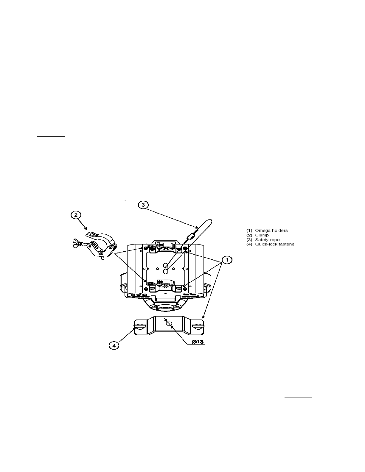
Installation via the Omega U Brackets.
safety device (a safety cable).
Screw one clamp (the clamp is not provided with MY575w) onto each of the two Omega U brackets supplied
with MY575w.
Insert the quick-lock fasteners of the first Omega bracket into the respective holes on the bottom of MY575w.
Tighten the quick-lock fasteners fully clockwise. Install the second Omega U bracket. Please do not use pliers,
crest wrenches and the like to turn the quick-lock fastener. If you do, there is very real likelihood that you will
break the Omega bracket. (These can be replaced at a substantial cost to your boss!)
Pull the safety cable through the holes on the bottom of the base and over the trussing or any secondary
point. Do not clamp the cable to the U bracket or clamp. That is not
A secondary safety point is any point that will adequately hold MY575w if the U brackets, clamps or the fixtures
base breaks or fails. Then the safety cable would be the backup and stop the fixture from falling to the ground.
- 4 - MY575 WASH
a secondary safety point.
fixing
DMX-512 Control Connection
Connect the provided XLR cable to the female 3-pin XLR output of your Elektralite CP20 or other DMX
controller. The other end should be connected to the male 3-pin XLR input of MY575w. You then daisy-chain
out of the first MY575w to the next MY575w. Never “Y” split the DMX connection.
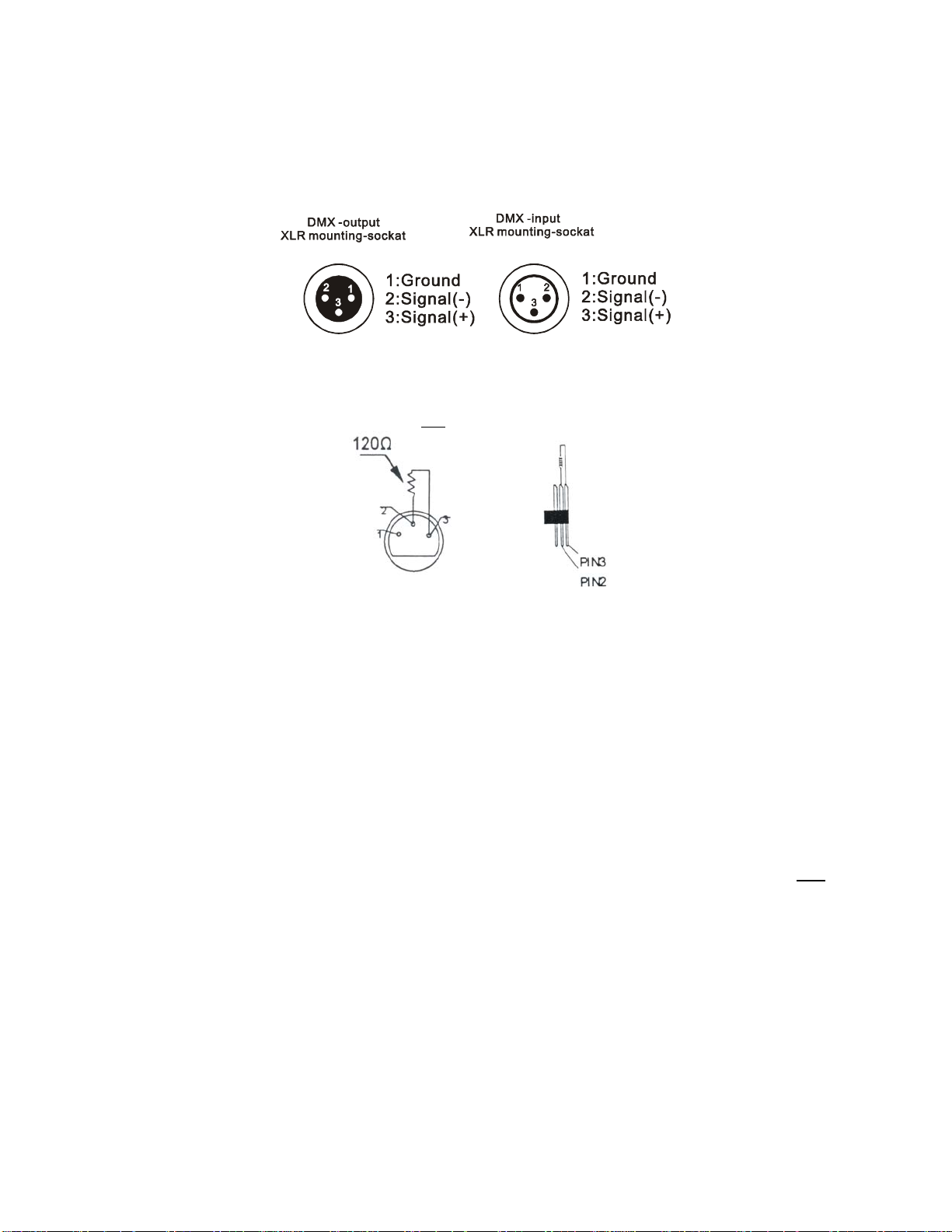
If you need more cable, then it should be two core, screened cable fitted with a 3 pin XLR input and output
connectors. Please refer to the diagram below.
DMX-512 connection with DMX terminator
For installations where the DMX cable has to run a long distance or is in an electrically “noisy” environment, it is
recommended that a DMX terminator is used. This helps prevent corruption of the digital control signal. The
DMX terminator is simply a 3 pin XLR plug (male) with a 120 Ω resistor connected between pins 2 and 3. It is
then plugged into the output XLR socket of the last
MY575w in the chain. Please see illustration below.
MY575 fitted with 5 pin XLRs
The MY575w can be fitted with 5 pin XLRs. The pin configuration is the same as the three pin connector.
So Pin 1 = ground, Pin 2 = Signal (-) and Pin 3 = Signal (+). Pins 4 and 5 are not used.
Projector DMX start address selection
All MY575w’s need be given a DMX starting address when using a DMX signal, so that the correct MY575w
responds to the correct control signals. This digital starting address is the channel number from which MY575w
starts to “listen” to the digital control information sent out from the Elektralite CP20 or other DMX controller.
The allocation of this starting address is done by setting the correct number on the display located on the base
of MY575w.
You can set the same starting address for all fixtures or group of fixtures, like all the MY575w’s in your plot, or
you can make different address for each individual fixture.
If you set the same address, all the fixtures will start to “listen” to the same control signal from the same
channel number. In other words, changing the settings of one channel will affect all the fixtures simultaneously.
If you set a different address, each unit will start to “listen” to the channel number you have set, based on the
quantity of control channels of the fixture. That means changing the settings of one channel will affect only
selected fixture.
In the case of this MY575w, which is a 18 channel fixture, you should set the starting address of the first unit to
1, the second MY575w to 19 (18 + 1), the third to 37 (19 + 18), and so on.
Note:
After switching on, MY575w will automatically detect whether DMX 512 data is received or not. If the data is received, the display will show
"A.001" or whatever the address is set to, like “A.019” If there is no data received at the DMX-input, the display flashes "A001" with the
actually set address. This situation can occur if:
- the 3 PIN XLR plug (cable with DMX signal from the controller) is not connected to the input of MY575w.
or
- the controller is switched off or defective.
or
- if the cable or connector is defective
or
- if the signal wires are swap in the input connector. In others words, pins 1, 2 and/or 3 are not the same at both ends. Believe it or
not this is very easy to do if the person making the cable does not look at the pin numbers in the connector. The numbers of the
pins and the color of the cable need to match. Don’t just “look” at the cable and assume they are correct!
the
- 5 - MY575 WASH

The Display Panel:
The Display Panel offers several features: you can set the starting address, switch on and off the lamp, run the
pre-programmed program or make a reset. It has been updated so if you have earlier my575w beware of the
changes! These updates are a direct result of customer feedback.
Probably the most important changes are:-
1. To change DMX address you must enter the Mode menu. You cannot just press the up and
down buttons to change the address.
2. The default for the lamp striking is from the board channel 14. The fixture’s lamp will not just
start up when you turn on the fixture.
The main menu is accessed by pressing (and holding) the Enter-button for 3 seconds until the display starts
flashing. Browse through the menu by pressing the Up-button. Press the Enter-button in order to select the
desired menu. You can change the selection by pressing the Up-button. Confirm every selection by pressing
the Enter-button. You can leave every mode by pressing the Exit-button. The functions provided are described
in the following sections on the next page.
- 6 - MY575 WASH
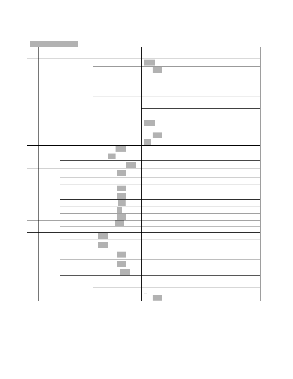
Default settings shaded.
Main
menu
0 MODE
1 LAMP
Sub menu Extension Display Function
ADDR
RUN
DISP
OPEN
ONLI
DELA
VALU A001~A511 (AXXX)
SLAV
AUTO
SOUN
VALU
RDIS ON/OFF 180º Reverse display
CLDI
ON/OFF Lamp on/off
ON/OFF
D–00 ~ D-59,D-15 Delay lamp on
ON/OFF (SLAV) Slave setting
ALON (AU-A)
MAST (AU-M)
ALON (SO-A)
MAST (SO-M)
D–00 ~ D-30
(DXXX)
ON/OFF Shut off LED display
DMX address setting
Automatic Program Run
in Stand Alone mode
Automatic Program Run
as Master
Sound-controlled Program
Run in Stand Alone mode
Sound-controlled Program
Run as Master
Display the DMX 512 value
of each channel
Lamp on/off via controller
2 SET
3 ADJU
4 TIME
5 EDIT
RPAN
VER
LODA
REST
DEGRE
16BI
RTIL
LADJ
TEST
MATI
LATI
CLMT
CLLT
STEP
SC01
~
SC48
ON/OFF Pan Reverse
V1.0-V9.9 Software Version
ON/OFF Restore Default factory setting
ON/OFF Reset
540/630 540º or 630º Pan Degrees
8/16 8 or 16 Bit control
ON/OFF Tilt Reverse
ON/OFF Lamp adjustment
T–01 ~ T–30 Test function of each channel
0000~9999 (hours) Fixture running time
0000~9999 (hours) Lamp running time
ON/OFF Clear fixture time
ON/OFF Clear lamp time
S–01 ~ S–48 Steps of Program Run
C–01 ~ C–30
TIME (sec.) T – – X (1~9) Time for each scene/cue/look
CNIN
01XX (00~FFH)
30XX (00~FFH)
ON/OFF Edit program via controller
Edit the channels of each
scene/cue/look
- 7 - MY575 WASH
 Loading...