

elektraLite eyeBall IP65 User Manual
elektraLite
eyeBall IP65
USER MANUAL
70, Sea Lane, Farmingdale, NY11735, U.S.A.
T. +1 (631)-396-0184. F. +1 (631)-396-0190
Elektralite (a division of Group One),
WWW.MYELEKTRALITE.COM

1. Unpacking
Thank you for choosing the elektraLite eyeBall IP65 fixture. For your own safety, please read this
manual before installing the fixture. This manual covers important information on installation and
applications. Please keep this manual for future reference.
The eyeBall IP65 fixture uses 7 high powered 12 watt leds in a balanced arrangement giving
incredible output. Please unpack it carefully and check whether it was damaged in shipping.
The following items should be in the box with the fixture:-
A short cable with a water resistant connector at one end and an Edison connector at the other.
A short cable with a water resistant connector at one end and a 5pin Male DMX connector at the
other.
2. Safety Instructions.
This device has left the factory in perfect condition. In order to maintain this condition and to ensure
a safe operation, it is absolutely necessary for the user to follow the safety instructions and warning
notes written in this user manual. The eyeBall IP65 is a high voltage fixture. Be careful when
dealing with high voltages.
Please read this manual. If you do not read this manual and damages occur to the eyeBall
IP65, then it could void the warranty.
The electric connection must be carry out by a qualified person and it is absolutely essential that the
eyeBall IP65 be grounded. This is imperative and is a safety issue. So under no circumstances
break off the ground pin on the Edison plug or use the fixture where a ground is not present. A
ground pin, like the fuse for the eyeBall IP65 is there for safety.
Always disconnect the eyeBall IP65 from the power source, when the device is not in use or before
cleaning it. Only unplug eyeBall IP65 from the power cord. Never pull out the plug out by pulling on
the power cord.
Please keep the eyeBall IP65 away from children and the general public. Please be intelligent and
use common sense when operating the eyeBall IP65.

3. General Guidelines.
ElektraLite eyeBall IP65 is a lighting fixture for professional use.
ElektraLite eyeBall IP65 should only be operated at between 120 to 240 volts.
ElektraLite eyeBall IP65 should not be operated 24/7 (24 hours a day; 7 days a week).
ElektraLite eyeBall IP65 needs operation breaks to ensure that it will work for a long time without
problems. Please do not shake the eyeBall IP65 and avoid using brute force when installing or
operating it.
When choosing the location to install the eyeBall IP65, please make sure that it is not exposed to
extreme heat. Make sure that the fixture has a good amount of free space around it for air flow. Do
not install it in a confined space or have insulation around the fixture. The minimum distance
between the eyeBall IP65 and the illuminated surface must be more than 3 feet.
Always mount the eyeBall IP65 with an appropriate safety cable.
Operate the eyeBall IP65 only when you are familiar with the features on the fixture. Do not permit
operation by persons not qualified.
All modifications to the eyeBall IP65 will invalidate the warranty. There are absolutely no
exceptions.
If eyeBall IP65 is operated in any way different to the one described in this manual, eyeBall IP65
maybe damaged and the guarantee will be void.
4. Installation
Please ensure that the eyeBall IP65 is hung using the appropriate "C" clamp or half cheeseboro.
A safety chain or cable should also be used as a secondary point of holding the fixture in case the
clamp comes loose. Never hang the fixture without a safety chain or cable.
If you are not qualified or have any doubts about hanging the eyeBall IP65 then do NOT hang it.
Do not clamp the cable to the U bracket or clamp. That is not a secondary safety point.
A secondary safety point is any point that will adequately hold the eyeBall IP65 if the "C" clamp or
half cheesboro fails. Then the safety cable would be the backup and stop the fixture from falling to
the ground. So do NOT fix the safety to the same place that the "C" clamp is attached.
The eyeBall IP65 is kept cool by conducting the heat away from the leds using the body's fin design.
As a result the fins and the surrounding area should be "open" all around the fixture. Do not block
the fixture into a tight location. For example,Do not try to mount the eyeBall IP65 like a "high hat" in
a soffit surrounded by insulation; the fixture would fail to operate due to overheating.
5. DMX-512 Control Connection and Power Connection
POWER:
The eyeBall IP65 comes with an Edison 120V connector to an outdoor water resistant connector
cable. Extension cables (water resistant connector to water resistant connector) are available as
accessories.
DMX 512 CONTROL:
The eyeBall IP65 come with a 5 pin XLR connector to an outdoor water resistant 3 pin connector
cable.
Extension cables (water resistant connector to water resistant connector) are available as
accessories.
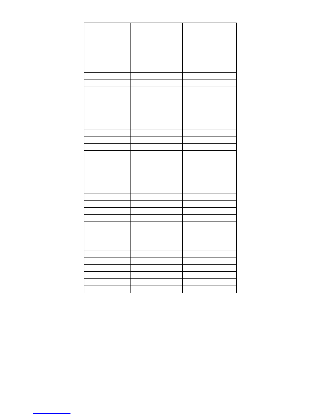
6. Menus in the fixture.
Root Menu Sub Menu 1 Sub Menu 2
STAT (STATIC LOOK) RED 0-255
GREEN 0-255
BLUE 0-255
WHITE 0-255
STROBE 0-255
AUTO (AUTOMATIC) Red
Green
Blue
Yel l o w
Cyan
Purple
White
Effect #1
Effect #2
Effect #3
RUN DMX 512
SLAVE
ADDRESS ASSIGN DMX CHANNEL 1-512
ID address 1-255
PERSONALITY STAG(E)
ARC.1
ARC1.D
ARC2
AR2.D
AR2.S
HSV
SETTINGS DTV NTSC/PAL
RGB→White ON/OFF ***
DIMMER 000(OFF), 001, 002, 003 or 004
RESET Password required*
FAN OF F
AUTO
LOW
NORMAL
HIGH
OFF
KEY LOCK OFF **SEE BELOW
ON
*The Password for the reset is using the up and down buttons when in the reset menu. The screen will
initially display [ ]. The following needs to be pressed ↑↓↑↓↑↓ then press Enter. The screen will then
display the word "OK" for 2 seconds and the fixture will reset.
**The Password for Key Lock is the same as reset. If key lock is ON then everytime you power up the
eyeBall IP65 the Password is requested. The password must be put in the eyeBall IP65 display otherwise
no changes can be made to the operation of the eyeBall IP65.
***RGB→White. If this feature is turned on the Output of the RGB and white can be adjusted for maximum
output. Normally the R, G, B, and W all default to maximum of 255 output. However this can be change for
each of the color components from a value of 128 up to 255.
 Loading...