

Elektral ThruScan, ThruScan s3, ThruScan s9, ThruScan sX, ThruScan sX-i User Manual
...
@
@
r
European Branch:
Elektral Businesspool GmbH
Hatzper Bogen 27,
D-45133 Essen
GERMANY
Phones :+49(0)201 814 10948
Fax :+49(0)201 364 4342
e-mail :elektral
elektral.com
WTMD
UUsseerr’’ss MMaannuuaal
MAIN CONTACT-FACTORY:
Elektral Elektromekanik A.S.
Ataturk Industrial Zone
M.K. Ataturk Blv. 23 Cigli
35620 Izmir -TURKEY
Phones : +90(0)232 376 7300
Fax : +90(0)232 376 7030
e-mail : elektral
elektral.com.t
www.elektral.com.tr
www.ThruScanmetaldetectors.com
Release: 05.12
l
Form: GKD s9sX50125

Contents Page
PRAFACE............................................................................................................ 4
Contents............................................................................................................. 5
Before Use .........................................................................................................6
1. GENERAL DESCRIPTION .................................................................................. 8
1.1 ThruScan s3 Walk Through Metal Detector............................................ 9
1.2 ThruScan s9 Walk Thru Metal Detector…………………………………………10
1.3 ThruScan sX Walk Through Metal Detector..........................................11
1.4 ThruScan sX-i Walk Through Metal Detector........................................12
1.5 ThruScan sX-WP Walk Through Metal Detector...................................13
2. INSTALLATION INSTRUCTIONS ......................................................................14
2.1 Site Selection ............................................................................................14
2.2 Assembling & Mounting ..........................................................................14
2.2.1 Assembling.............................................................................................14
2.2.2 Assembling.............................................................................................12
2.2.3.4. Assembling ........................................................................................14
2.2.- 5.6.7.8.9.10.11.12.13.14 Assembling ...............................................15
3. CONTROL DISPLAY PANEL & INDICATION INFORMATION ........................16
3.1 Control Panel.............................................................................................16
3.1.1 LCD Display ............................................................................................16
3.1.2 Alarm Locater Display ..........................................................................16
3.1.3 LED VU Display....................................................................................... 16
3.1.4 Battery Indicator....................................................................................17
3.1.5 Pacing Light Indicator-(Traffic Lights) ................................................17
3.2 Touch Pads ...............................................................................................17
3.2.1 ON- OFF Button ......................................................................................17
3.2.2 RUN(X) Button........................................................................................17
3.2.3 SEL(√) Button .........................................................................................17
3.2.4 Up-Down Buttons...................................................................................17
3.3 Traffic Lights..............................................................................................18
3.4 Zone (Indicator) Light’s ............................................................................ 18
3.5 Various Alarms ..........................................................................................18
3.6 Relay-Contact Outputs .............................................................................19
3.7 Synchronization and Remote Control Outputs.....................................19
4. PROGRAMMING & SET UP .............................................................................20
4.1 Program MENU..........................................................................................20
4.1.1 Security Level & Sensitivity Level Adjustments................................20
4.1.2 Zone Security Level & Sensitivity Level Adjustment (sX) ................23
4.1.3 Auto Detection & Auto Sensitivity Assign (sX)..................................24
1

Contents Page
4.1.4 Alarm & Tone Volume Adjustment.....................................................25
4.1.5 Alarm Counter........................................................................................25
4.1.6 In-Coming / Out-Going Counter (Traffic Counts)...............................25
4.1.6.1 For ThruScan s3 .................................................................................25
4.1.6.2 For ThruScan s9/sX/sX-i/sX-WP .....................................................26
4.1.7 Factory Settings.....................................................................................26
4.1.8 Language Selection ..............................................................................27
4.1.9 Counter Visibility....................................................................................27
4.1.10 New Password .....................................................................................27
4.1.11 Environment Noise Level ...................................................................28
4.1.12 Pass Sensor .........................................................................................28
4.1.13 Alarm Tone Duration Select ..............................................................28
5. SYSTEM OPERATION .......................................................................................29
5.1 Normal Operating Mode ..........................................................................29
5.2 Routine Tests.............................................................................................29
5.3 Alarm State................................................................................................30
6. TECHNICAL SPECIFICATIONS ........................................................................30
6.1 Electronics..................................................................................................30
6.2 Detection Field ..........................................................................................30
6.3 Language ...................................................................................................31
6.4 Self Test......................................................................................................31
6.5 Sensitivity...................................................................................................31
6.6 Memory ......................................................................................................32
6.7 Traffic Counter...........................................................................................32
6.8 Tamper Proof.............................................................................................32
6.9 Regulatory Information............................................................................32
6.10 Infrared Sensor .......................................................................................32
6.11 Electromagnetic Noise & Interference Rejection..............................33
6.12 Masking ...................................................................................................33
6.13 Synchronisation ......................................................................................33
6.14 Electrical Requirements........................................................................33
6.15 Operating Temperatures .......................................................................34
6.16 Humidity ..................................................................................................34
6.17 Throughput Rate.....................................................................................34
6.18 Weight......................................................................................................34
6.19 Warranty Period......................................................................................34
6.20 Dimensions .............................................................................................34
7. OPTIONS............................................................................................................35
7.1 Remote Control Package ........................................................................35
2

Contents Page
7.1.1 SCADA Remote Control Software-SRC ..............................................35
7.1.2 Specific MODEM for Remote Control Program ................................36
7.1.3 Special CABLE for Remote Control Program ....................................36
7.2 Outdoor Package ...................................................................................... 36
7.2.1 Rain Protect Shelter.............................................................................36
7.2.2 Side Panel Protection ...........................................................................37
7.3 Battery Group ............................................................................................37
7.4 WTMD Wheeler .........................................................................................37
7.5 Carriage Bag..............................................................................................37
7.6 IRDA Remote Control...............................................................................37
8. MAINTENANCE & REPAIR............................................................................... 37
8.1 Periodic Maintenance ..............................................................................37
8.2 Repair .........................................................................................................34
8.3 Module Replacement...............................................................................38
8.4 Warranty Provisions .................................................................................38
9. TROUBLE SHOOTING .......................................................................................39
9.1 Frequently Asked Questions ...................................................................39
9.2 Mounting Questions .................................................................................40
9.3 Operational Questions .............................................................................42
10. APPENDIX.......................................................................................................44
10.1 Certificate of Expertise .........................................................................44
10.2 SRC SCADA Remote Control ................................................................44
10.2.1 ThruScan s9-SRC SCADA Program Manual ....................................45
10.2.2 ThruScan sX-SRC SCADA Program Manual ....................................46
10.3 IRDA Remote Control Unit Manuel......................................................47
10.4 Users Manuel For Wheeled Transportation …………………................ 48
10.5 Certificate of Warranty .......................................................................... 49
© 2005 Elektral A.Ş. – ThruScan Metal Detectors
All rights reserved. Protected by Law Number 4110 and Ideas and Works of Art Law 5846, unless a written consent by its copyright owner, Elektral A.Ş. according to the 52. Article is provided, this manual, under no
circumstances may be processed, copied, its duplicated copies published, represented, presented, in any form or by any means by mechanical and/or electronic ways be transmitted or used.
3

PREFACE
Dear User;
You have taken some serious measures for the security of the Entrance-Control of
necessary environments with the Magnetic Walk Through Metal Detector-(WTMD)
you have purchased. Thank you for selecting of ELEKTRAL warranty.
With Elektral-
ThruScan
(s3/s9/sX/sX-i/sX-WP) Multizone Walk Through Metal
Detectors, your estates will be more secured.
ThruScan
; are our metal detectors which include norms and regulations written in
this field, approved by international markets with incredible references.
ThruScan
will receive your approval as well with their quality, service guarantee
and economy.
Thank you for selecting a product manufactured by Elektral A.S. at an international
alliance. We hope to meet at many professional Elektral products.
Please make sure to read this manual carefully before start up this versatile
electronic equipment.
Elektral Products,
Are produced in environment friendly modern facilities
Without no harm to the nature and to living creatures.
MADE IN TURKEY
ALTERATIONS RESERVED.
NO CLAIMS CAN BE ACCEPTED BY OUR FIRM REGARDING THE APPLICATIONS OF
THIS INSTRUMENT FROM THE SECOND OR THIRD PARTIES.
ALL THE RIGHTS RESERVED.
PLEASE FIND OUR “Conditions of Sales, Delivery & Warranty” at our Web.
4
C O N T E N T S
Procedures and Safety Warnings before using
Technical specifications of
Preparations Mounting
ThruScan
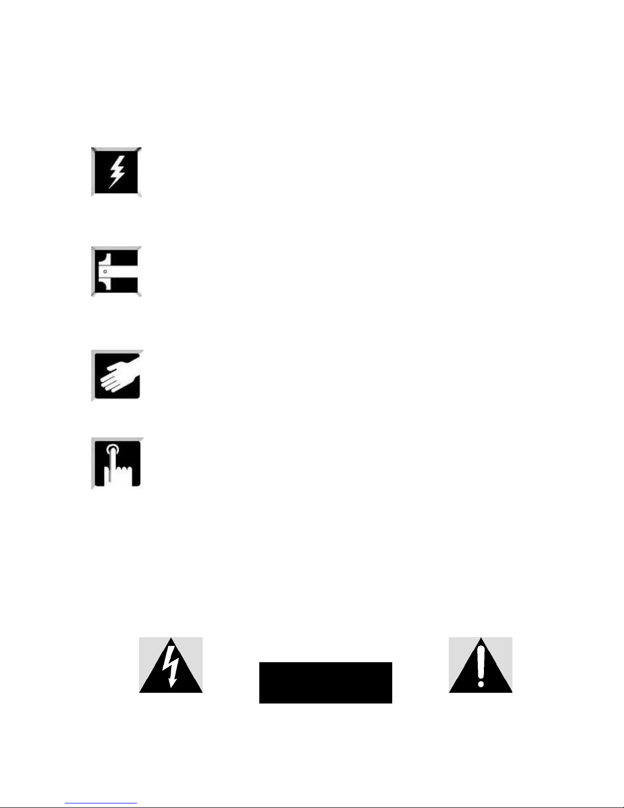
The arrow-end lightning symbol inside
the equilateral triangle informs the user
that in the context of the product, there
is enough amount of ‘uninsulated’
dangerous voltage to cause an electric
shock.
ThruScan
ThruScan
Programming and further procedures
DO NOT OPEN ThruScan
ELECTRONIC CASE
RISK OF ELECTRIC SHOCK
The exclamation mark inside the eqilateral triangle informs
the user that there are important instructions of useage and
information inside the booklets given with the equipment.
5
Necessary Procedures and Safety Warnings
Prior to Using
ThruScan
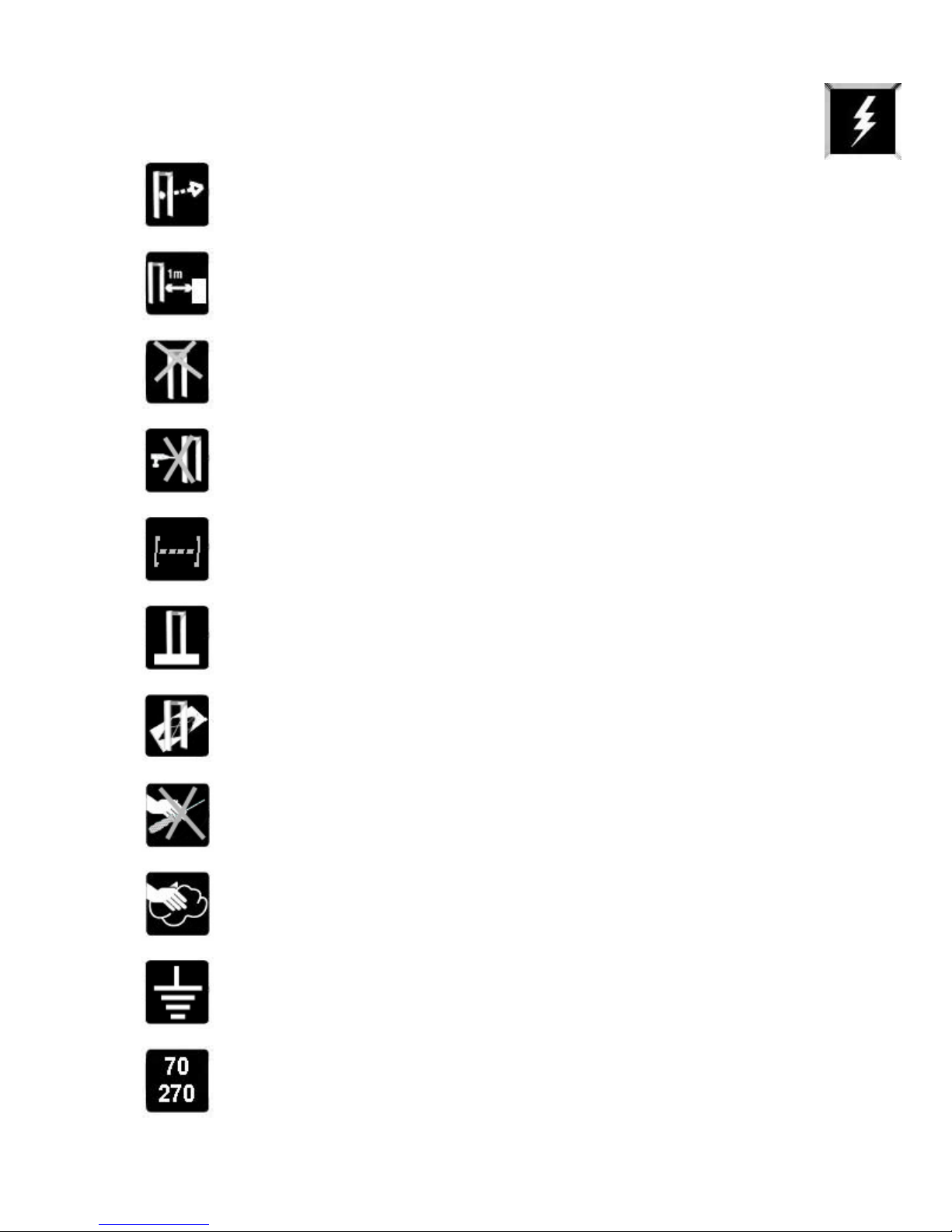
Avoid direct light from entering to the infrared sensors apertures
(see Sec. 6.10) of your
ThruScan
.
Leave minimum 1m between your
as metal doors, X-Rays, turnstiles, as such.
Do not place any covers, plating or loads that would induce weight
over your
Do not drill any holes on the panels of your
circumstances.
Your
electronic PIN CODE as a precaution towards unauthorized people.
Do not share your password. Contact factory when it is fogotten.
Assemble your
fix it firmly to the floor.
ThruScan
ThruScan
unless being recommended by the factory.
is secured both by a mechanical lock and an
ThruScan
on a horizontal and flat floor. Make sure to
ThruScan
ThruScan
and any objects such
under any
Do not assemble your
Do not let unauthorized persons to interven
units. Contact your dealer or the factory for authorized service staff.
Use soft, damp clothing to clean your
your equipment during cleaning.
Never Operate! your equipment through mains without norm ground
ThruScan
Hz on a switching power unit. However you normally should operate
on 110-220VAC.
is designed to operate between 70~270 VAC / 50Hz~60
ThruScan
on a floor that is not rigid or stable.
ThruScan
6
ThruScan
. Always unplug
s electronic
CAUTION! Misuse of this equipment specified by the manufacturer may
result in damage to property or injury to persons.
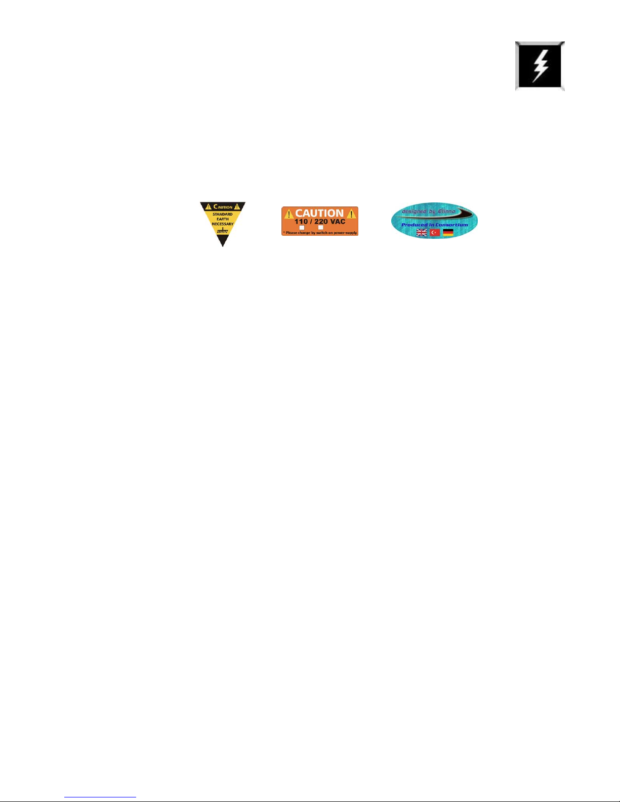
Technical Specifications:
Electrical : Select 110VAC or 220VAC by the Switching Supply Module by opening the
cover of the control unit.(Factory default 220 VAC)
70 – 270 VAC (Supply should be earthed & stable)
10 Watts standby, 20 Watts max in alarm. A-Class Energy Save
Frequency: 50/60 Hz
Maximum Relative Humidity : 95% non-condensing
Operating Temperature : -20° ~ +70º C
WARNING:
All of the ThruScans and the PC of the SRC-SCADA Remote Control, must be powered at
the same point for the same "ground/earth". Otherwise problems may occur due to
potential difference.
Standards:
The units conform to NILECJ L/1-3 standards
ThruScan
Administration). It has been certified by experts that has no effects on the peacemakers, the
pregnant women and as well at magnetic media. A “report of expertise” on this issue is presented
in Attachment-1. See Section 10.1.
Protect your
stable floor without vibration.
DO NOT place the
transformers, power cables, or control circuits; excessive electrical noise may cause false
measurements.
is within the magnetic emission limits approved by FDA (American Food & Drug
ThruScan
from direct rain, mist and/or condensation and place water level on a
ThruScan
close to telephone lines, television monitors, electric motors,
CAUTION! ThruScan must be firmly anchored to the floor to reduce the accidental risk
of fall down and thus injure persons or cause property damage.
Do not drive nails, screws or drill holes into the side panels.
Screen only when the green “ready LED” is on to ensure proper operation.
Test your apparatus daily especially against environmental displacements.
Security metal detectors are designed to use within a total security-screening
plan. It is the last user’s responsibility to define the overall plan and ensure that
NOTE:
it operates effectively.
7

1. GENERAL DESCRIPTION
ThruScan
microprocessor controlled, digital pulse induction utilizing VLF Technology that provide superior
metal discrimination and detection. It is a versatile and easily portable walk-through metal
detection unit providing a high level of detection with a walk-thru rate of up to 60 persons per
minute.
ThruScan
comprises of several horizontal and vertical zones, which can detect metal objects within 9 separate
scanning zones of the WTMD
improved all through the passage dramatically by revealing the exact locations that are threat. The
operator need only to search the
See Section 3.4
A bright, highly visible LED (Light Emitting Diode) VU display provides a visual indication of the level
of metals detected within the field of detection. Operator may also approximate the magnitude of
the metal by warning sound without looking the
Traffic LED’s (Green or Red) on the side panels (ENTER SIDE) show if WTMD is ready for passage.
If the lights show green the gateway may be entered, if the lights show red the person must not
enter. See Section 3.3
Zone lights show the location of the metal object whether it is on the left, right, top, bottom or at
the centre of the body and are located on the side panels of the exit side of the gateway. Zone
lights originate from LED arrays of 2x6 to show 9 zones. These zones are being indicated on the
control panel also by “Graphic Zone Leds (Locator)”.
A backlited LCD Display (monitor), (See Program MENU Section 3.1.1) is located on the overhead
Control Unit and display operational information, including program, alarm and sensitivity settings
as well as a traffic count of both in-coming and out-going passing’s.
A see through cover with mechanical lock
Control Unit in order to prevent unauthorized tampering. Calibration and control settings are
further protected by a Programmable 4 digit
ThruScan
ThruScan s3)
operation for up to 4 hours (longer times optional) in case of mains failure. The WTMD
automatically shuts itself down in case of the lack of the necessary voltage.
Another unique feature of the
(* for ThruScan s3/s9 sixteen WTMDs for 1 PC) ThruScan
even remotely from anywhere in the world via a standard and satellite(thuraya) telephone lines
under a modem connection. The hardware for this feature is built in as a standard and the SCADA
software and connection cables are available separately as an option. See Section 7.1
Other features of the
electronics are built into the overhead Control Unit, connection with the panels provided with
sockets, eliminating the problems often associated with a cable-connected console.
s3/s9/sX/sX-i/sX-WP WTMD’s all are simple to operate and with advanced
(* for ThruScan s3 aprx. 30 persons/min)
s9/sX/sX-i/sX-WP has an enlarged stable and homogeneous detection field that
(*for ThruScan s3 three zones).
ThruScan
’s s9/sX/sX-i/sX-WP indicated by the side panel lights.
ThruScan
Detection field homogeneity is
’s VU-meter on the Control Panel.
(*for ThruScan s3 traffic lights are under Control Panel at gateway)
(*for s3, display only at control panel)
(* optional for ThruScan s3)
enable to access to
PIN CODE. See Section 6.8
(s9/sX/sX-i/sX-WP) also incorporates an integral UPS battery back up
supply mains to protect the mains from power fluctuations and to maintain
ThruScan
ThruScan
include superior sensitivity, stability and noise rejection. All
sX/sX-i/sX-WP is its ability to monitor up to 99 separate
units remotely from a PC or
(*optional for
8
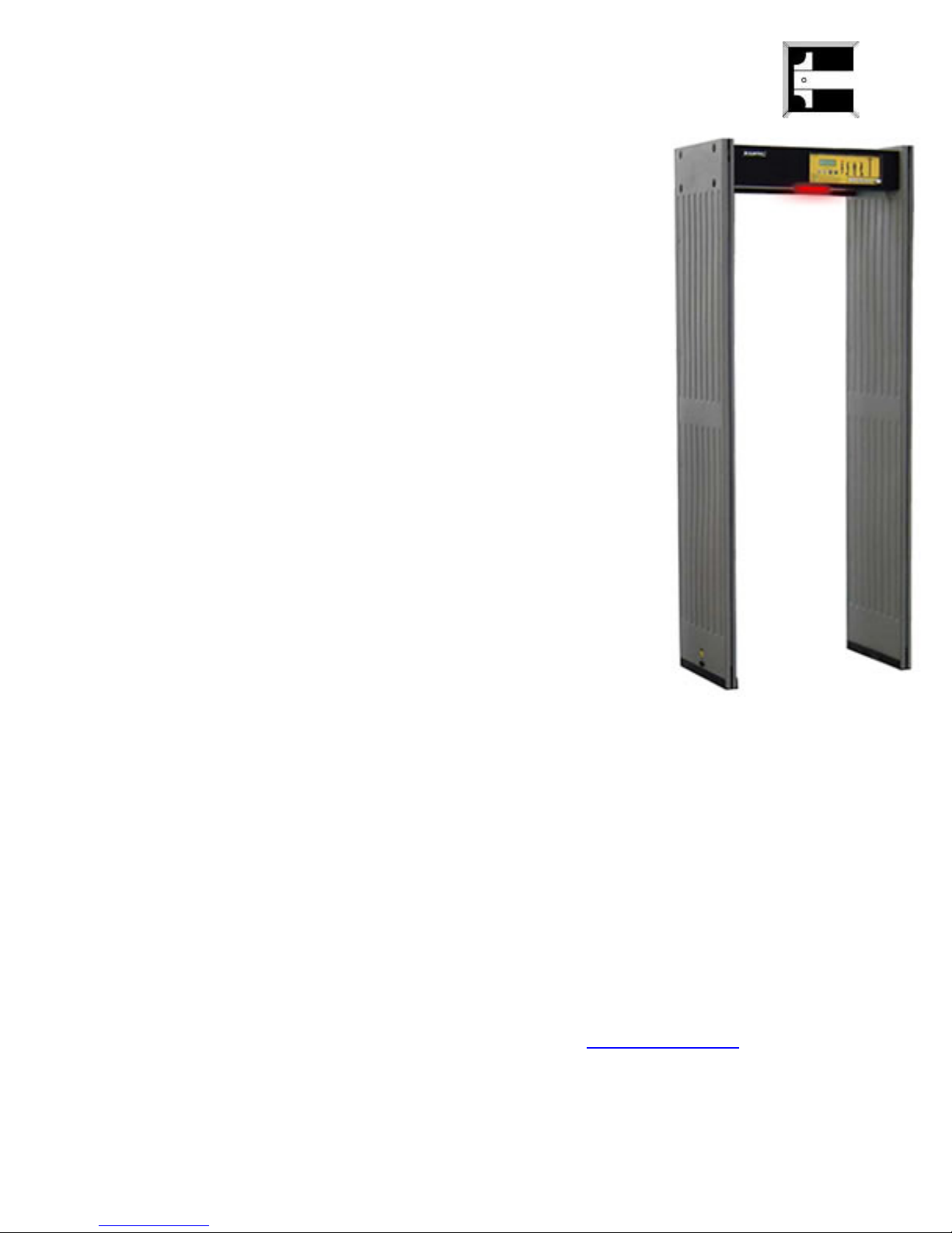
1.1
ThruScan
• International Norms (NILECJ-0601 L1-3 / IP53/ IEC
348 Class1, in accordance with CE,
a ISO 9001-2000 certified ),
• MULTIZONE, 3 “Real Detection Zone” (Left, Middle,
Right),
• Auto Calibration,
• Compact Design,
• VLF Technology- human friendly certification,
• Green/Red Bicolor Traffic Through LEDs,
• 10 Sensitivity Levels,
246 adjustable levels at each, applicable to all zones,
separately (Program 1 fixed to NILECJ - NC),
• Graphic Zone Display on control panel,
• Display of Metal Density at 10 levels
(green/yellow/red) VU meter,
• Environmental Magnetic Noise Level Display,
• 10 different and 10 level adjustable warning tones,
• Alarm Counter,
• In Counter(one way) at 5 Digits (Visible/Invisible),
• 4 Digit changeable PIN CODE,
s3
Manufactured in
(* optional Mechanic
Lock)
• Automatic Failure Display,
• Reloading the Factory Default Settings by 1 touch
button,
• Easy Programming & Monitoring with LCD display
• Standard MENU in 4 Languages (English, German,
Turkish and Spanish),
• Additional NO/NC Relay Output for peripheral
security apparatus as turnstiles, cameras, recorders etc. during alarming
• Switching Power Supply,
• Modem/RS232 Output, for Remote Data Communication (SCADA SOFTWARE),
• Unique Designs & in variety of colours,
• Easy mounting/dismounting in aprx.15 minutes,
• With the Outdoor Package can be used at outside
• Exported to 4 continents.
(*option UPS).
(*option),
NOTE: You may reach ThruScan s3 Photo Gallery through www.elektral.com.tr website.
9
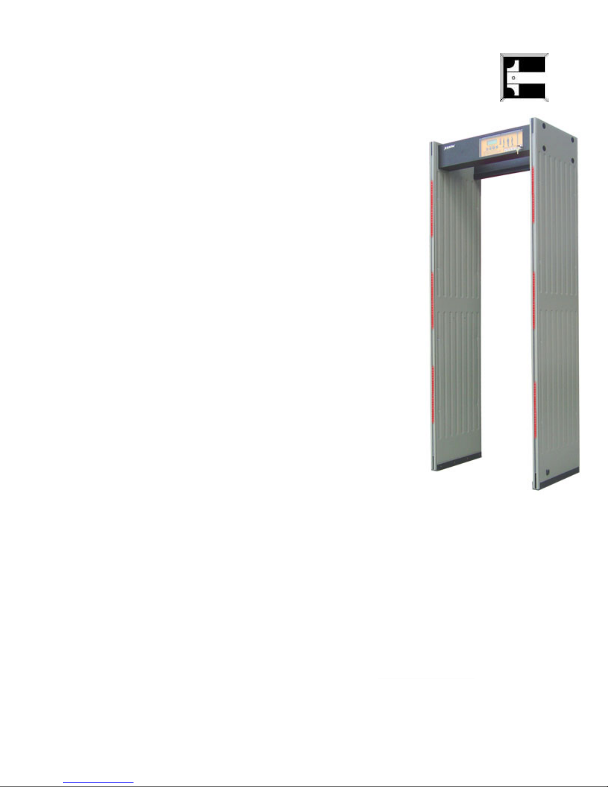
1.2
ThruScan
the norms it provides, its specifications, performance and economic advantages.
Here are some of the technical superiorities for
NOTE: You may reach ThruScan s9 Photo Gallery through www.elektral.com.tr website.
ThruScan
s9 was chosen, “The Best Deal” in Dubai Safety Exhibition-2001, with
• International Norms (NILECJ-0601 L1-3 / IP53/
IEC 348 Class1, in accordance with CE,
Manufactured in a ISO 9001-2000 certified ),
• MULTIZONE, 9 Real Detection Zone,
• Auto Calibration,
• Compact Design,
• VLF Technology- human friendly certified,
• Green/Red Bicolor Traffic Through LEDs,
• LED Illuminated Warnings at the Control and Side
Panels,
• 10 Sensitivity Levels,
246 adjustable levels at each, applicable to all
zones, separately (Program 1 fixed to NILECJ - NC),
• Graphic Zone Display on control unit,
• Display of Metal Density at 10 level
(green/yellow/red) VU meter,
• Environmental Magnetic Noise Level Display,
• 10 different and 10 level adjustable warning tones,
• Alarm Counter,
• In & Outgoing Counters separately at 5 Digits
(Visible/Invisible),
• Mechanical Lock For Control Panel and 4 Digit
changeable PIN CODE,
• Automatic Failure Display,
• Reloading the Factory Default Settings by 1 touch
button,
• Easy Programming & Monitoring with LCD display
• Standard MENU in 4 Languages (English, German,
Turkish and Spanish),
• Additional NO/NC Relay Output for peripheral security apparatus as turnstiles,
cameras, recorders etc. during alarming,
• UPS-Uninterrupted Switching Power Supply, 4 Hours operation without mains,
• Modem/RS232 Output, for Remote Data Communication (SCADA SOFTWARE),
• Unique Designs & in variety of colours,
• Easy mounting/dismounting in aprx.15 minutes,
• With the Outdoor Package can be used at outside
• Exported to 4 continents.
s9
ThruScan
s9 :
(*option),
10
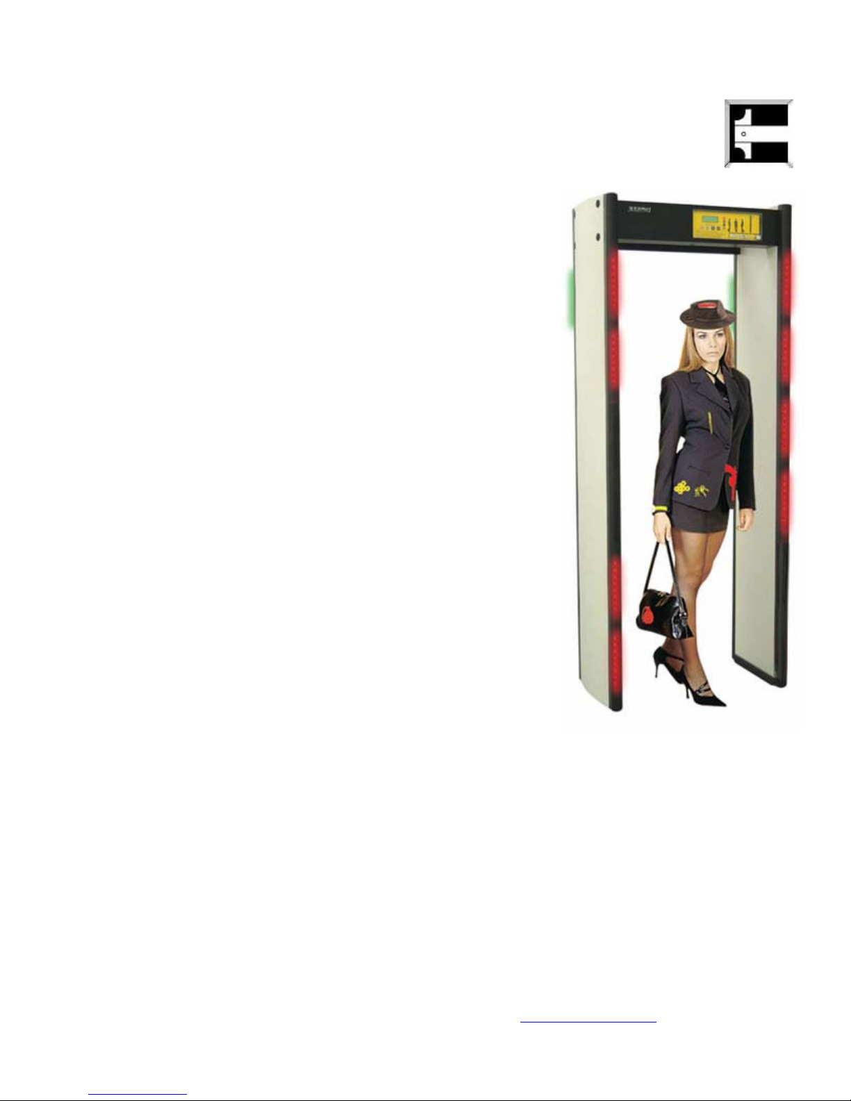
1.3
ThruScan
Security & Safety Exhibition-2003 with its innovative superior spec, compliance to
norms, contemporary design, performance and economic advantage, in comparison to
its counterparts. It’s widely used and preferred all around the world, protecting
millions of people against terror
ThruScan
sX was introduced as “The Breaking News” at Abu Dhabi –Middle East
• International Norms (NILECJ-0601 L1-3 / IP54/
IEC 348 Class1, in accordance with CE,
Manufactured in a ISO 9001-2000 certified ),
• MULTIZONE, 9 Real Detection Zone,
• Auto Calibration,
• VLF Technology- human friendly,
• Green/Red Bicolour Traffic Through LEDs,
• LED Illuminated Warnings at the Control and
Side Panels,
• 20 Sensitivity Levels, 246 adjustable levels at
each, applicable to all zones separately
(Program 1 fixed to NILECJ -NC), 5 fixed
International Sensitivity Standard (optional),
• Separate Zone Sensitivity Settings,
• Automatic Sensitivity Program selects the
correct sensitivity for a specific weapon or test
object-(fast consistent calibration) “SMART
DETECTOR”,
• Graphic Zone Display,
• Display of Metal Density at 10 level
(green/yellow/red) VU meter,
• Environment Magnetic Noise Level Display,
• 10 different and 10 level adjustable warning
tones,
• Alarm Counter,
• In & Outgoing Counters separately at 5 Digits
(Visible/Invisible),
• Mechanical Lock For Control Panel and 4 Digit
changeable PIN CODE,
• Automatic Failure Display,
• Reloading the Factory Default Settings by 1 touch button,
• Easy Programming & Monitoring with LCD display,
• Standard MENU in 4 Languages (English, German, Turkish and Spanish),
• Additional NO/NC Relay Output for peripheral security apparatus as turnstiles,
cameras, recorders etc. during alarming,
• UPS- Uninterrupted Switching Power Supply, 4 Hours operation without mains,
• Modem/RS232 Output, for Remote Data Communication (SCADA SOFTWARE),
• Modern, Contemporary,
• Unique Designs & in variety of colours,
• Easy mounting dismounting (15 Min.),
• With the Outdoor Package can be used at outside
• Exported to 4 continents.
sX
.
Elinno
/Innovative Design,
(*option),
NOTE: You may reach ThruScan sX Photo Gallery through www.elektral.com.tr website.
11

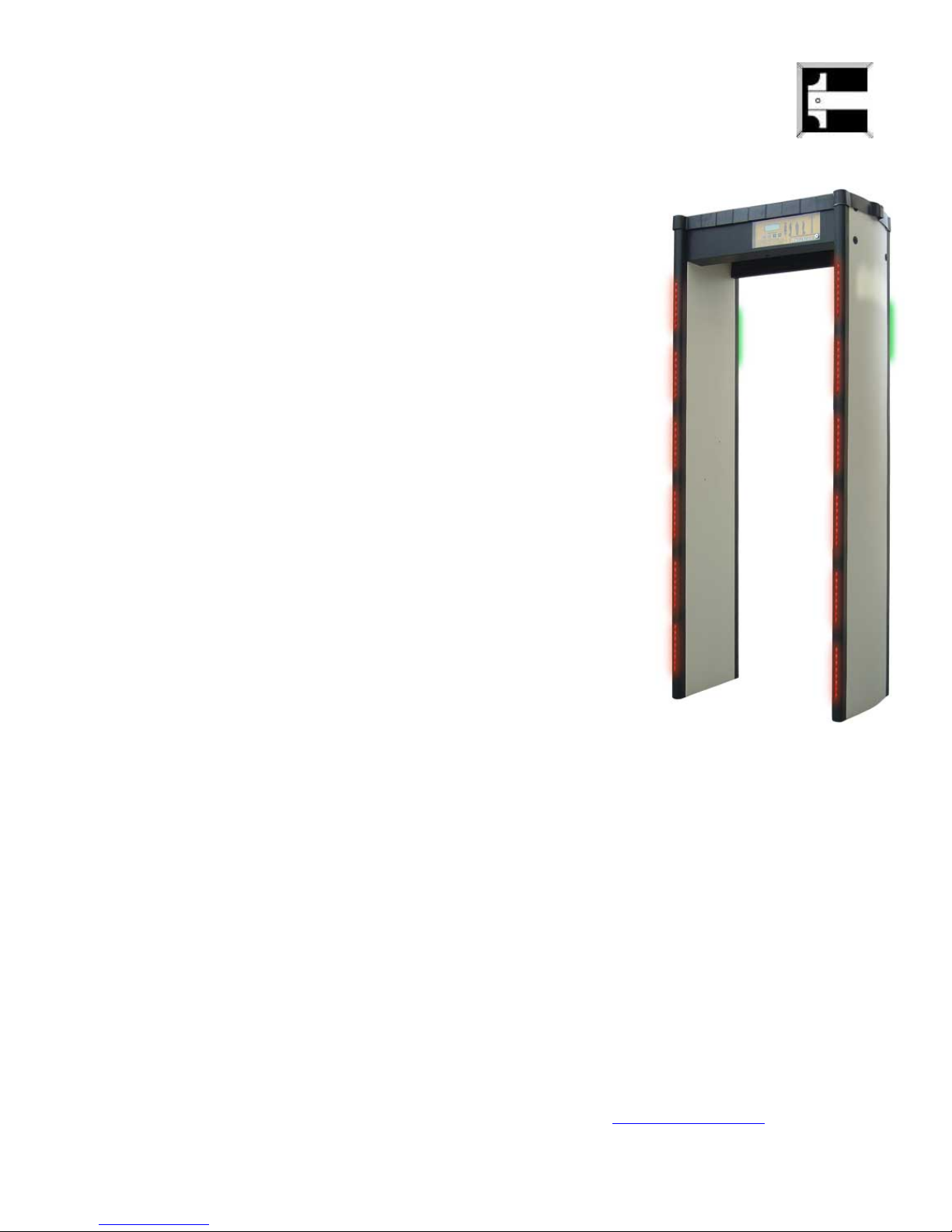
1.4
ThruScan
sX–i
• International Norms (NILECJ-0601 L1-3 /
IP54/ IEC 348 Class1, in accordance with CE,
Manufactured in a ISO 9001-2000 certified ),
• MULTIZONE, 9 Real Detection Zone,
• Auto Calibration,
• VLF Technology- human friendly certified
• Green/Red Bicolour Traffic Through LEDs,
• LED Illuminated Warnings at the Control and
Side Panels,
• 25 Sensitivity Levels, 246 adjustable levels
at each, applicable to all zones separately
(Program 1 fixed to NILECJ -NC) (jailhouse
sensitivity),
• Separate Zone Sensitivity Settings,
• Automatic Sensitivity Program selects the
correct sensitivity for a specific weapon or
test object-(fast consistent calibration)
“SMART DETECTOR”,
• Graphic Zone Display,
• Display of Metal Density at 10 level
(green/yellow/red) VU meter,
• Environment Magnetic Noise Level Display,
• 10 different and 10 level adjustable warning
tones,
• Alarm Counter,
• In & Outgoing Counters separately at 5
Digits (Visible/Invisible),
• Mechanical Lock For Control Panel and 4
Digit changeable PIN CODE,
• Automatic Failure Display,
• Adjustable alarming duration (0,5sec-2secs)
• Negligible false alarming by IR pass sensors!
(deletable function, see 4.1.12),
• Reloading the Factory Default Settings by 1
touch button,
• Easy Programming & Monitoring with LCD display,
• Standard MENU in 4 Languages (English, German, Turkish and Spanish),
• Additional NO/NC Relay Output for peripheral security apparatus as turnstiles,
cameras, recorders etc. during alarming,
• UPS- Uninterrupted Switching Power Supply, 4 Hours operation without mains,
• Modem/RS232 Output, for Remote Data Communication (SCADA SOFTWARE),
•
With/Without Cable connection tandem operation of multiple WTMDs,
• Unique Designs & in variety of colours,
• Modern, Contemporary,
Elinno
/Innovative Design,
• Easy mounting / dismounting (15 Min.),
• With the Outdoor Package can be used at outside
(*option),
• Exported to 4 continents.
NOTE: You may reach ThruScan sX Photo Gallery through www.elektral.com.tr website
12
1.5
ThruScan
weatherproofing & some other electronic features.
ThruScan
sX-WP has the same superior features as sX even improved in
• International Norms (NILECJ-0601 L1-3 / IP55/
IEC 348 Class1, in accordance with CE,
Manufactured in a ISO 9001-2000 certified ),
• IP 55 – For Outdoor Usage,
• MULTIZONE, 9 Real Detection Zone,
• Auto Calibration,
• VLF Technology- human friendly certified,
• Green/Red Bicolour Traffic Through LEDs,
• LED Illuminated Warnings at the Control and Side
Panels,
• 20 Sensitivity Levels, -246 adjustable levels at
each, applicable to all zones separately, 5 fixed
International Sensitivity Standard (optional),
• Separate Zone Sensitivity Settings,
• Automatic Sensitivity Program selects the correct
sensitivity for a specific weapon or test object(fast consistent calibration) “SMART DETECTOR”
• Graphic Zone Display,
• Display of Metal Density at 10 level
(green/yellow/red) VU meter,
• Environment Magnetic Noise Level Detection
Display,
• 10 different and 10 level adjustable warning
tones,
• Alarm Counter,
• In & Outgoing Counters separately at 5 Digits
(Visible/Invisible),
• Lock For Control Panel and 4 Digit changeable PIN CODE,
• Automatic Failure Display,
• Reloading the Factory Default Settings by 1 touch button,
• Easy Programming & Monitoring with LCD display,
• Standard MENU in 4 Languages (English, German, Turkish and Spanish),
• Additional NO/NC Relay Output for peripheral security apparatus as turnstiles,
cameras, recorders etc. during alarming,
• UPS- Uninterrupted Power Supply, 4 Hours operation without mains,
• Modem/RS232 Output, for Remote Data Communication (SCADA SOFTWARE),
• With/Without Cable connection tandem operation of multiple WTMDs,
• DC Power Supply (Switching Power Pack),
• Unique Designs & in variety of colours,
• Modern, Contemporary,
• Easy mounting /dismounting (15 Min.),
• Exported to 4 continents.
sX-WP ( Weatherproof Version)
Elinno
/Innovative Design,
NOTE: You may reach ThruScan sX WP Photo Gallery through www.elektral.com.tr website.
13
2 INSTALLATION
2.1 SITE SELECTION
Before choosing a site for
pedestrian traffic, space availability and overall environmental conditions.
Position and fix
or condensation. If WTMD will be used for a short time in outdoor then use “Rain Protect Shelter
(Hat)” as well as outdoor package. (See Section 7.2). ThruScan sX-WP is produced for outdoor
fulfilling IP55 standards.
To avoid external metal interference, ensure that there are no large metal items near
False alarms may be caused nearby the moving metallic such as an escalator or a revolving door as
well as due to an electrical interference from radio, telephones, television monitors, powerful
electronic motors and transformers.
Do the electrical installation of the WTMD preferably from the ceiling or from the floor (without
moving or stepping on it).
Protect your WTMD from humidity and water since it is versatile electronic equipment.
There is a very sensitive magnetic zone in the passing section of the WTMD. This magnetic zone
can easily be affected by shaking. Protect your
2.2
ASSEMBLING & MOUNTING
2.2.1 Verify that the following contents are included:
9 Left hand side panel
9 Right hand side panel
9 Main control & display unit
9 Back fixing crosspiece
9 Mains power lead
9 Synchronization connection cable
9 6 base fixing screws
9 8 panel fixing bolts
9 8 finishing bolt covers
9 Installation spanner (for panel fixing bolts)
9 Allen key (for base plate)
9 User’s manual
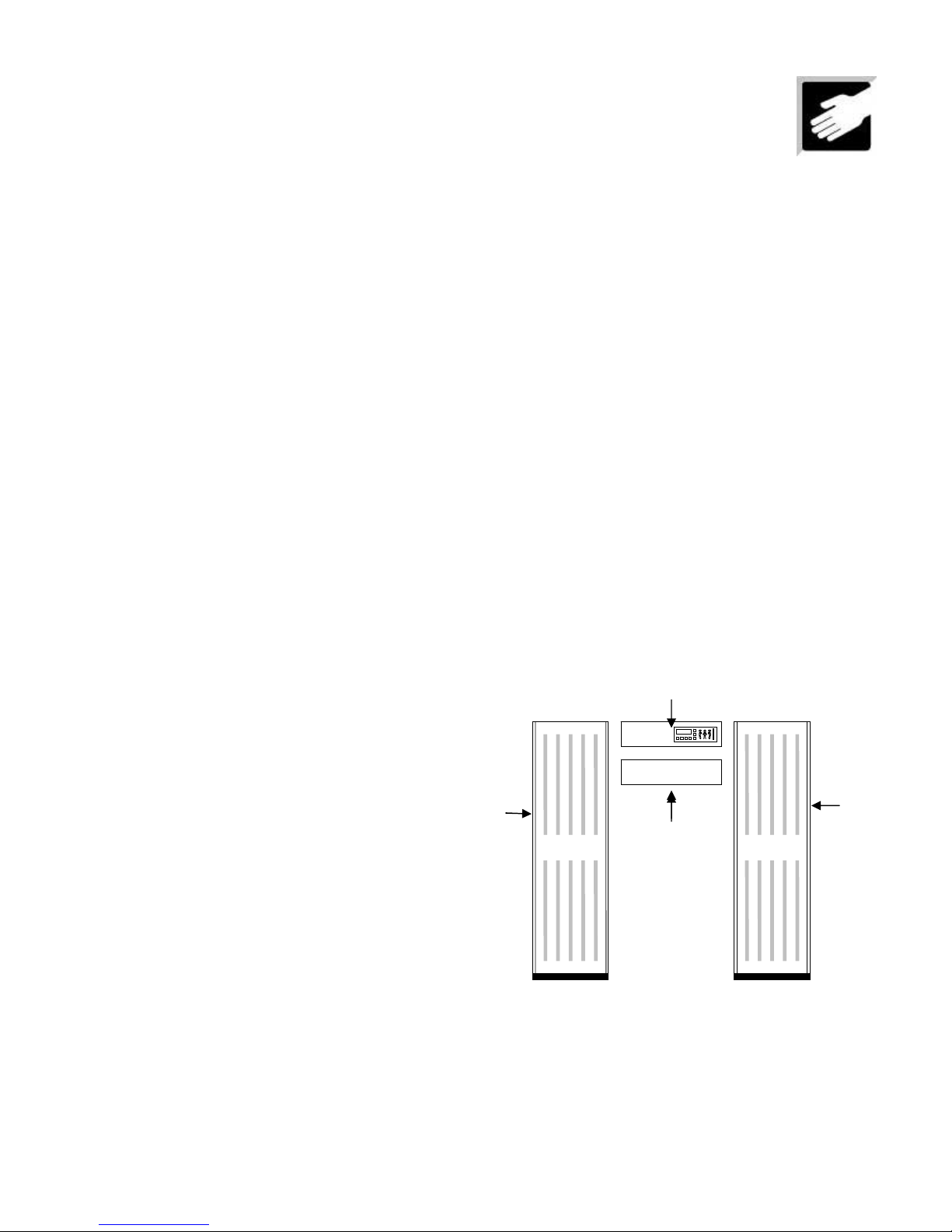
2.2.2 Arrange the major components as shown.
2.2.3 Lay the main Control Unit
surface
(the packing (bubbled pe) is ideal)
ThruScan
ThruScan
on a flat, stable floor where it remains unaffected by the sun, rain, mist
, it is important to consider the volume and throughput of
ThruScan
ThruScan
from such unstable situations.
Main Control & Display
Unit
Left
Side
Panel
(with the control panel facing down)
.
Back fixing
crosspiece
onto a soft, scratch free
.
Right
Side
Panel
14
 Loading...