

Page 1
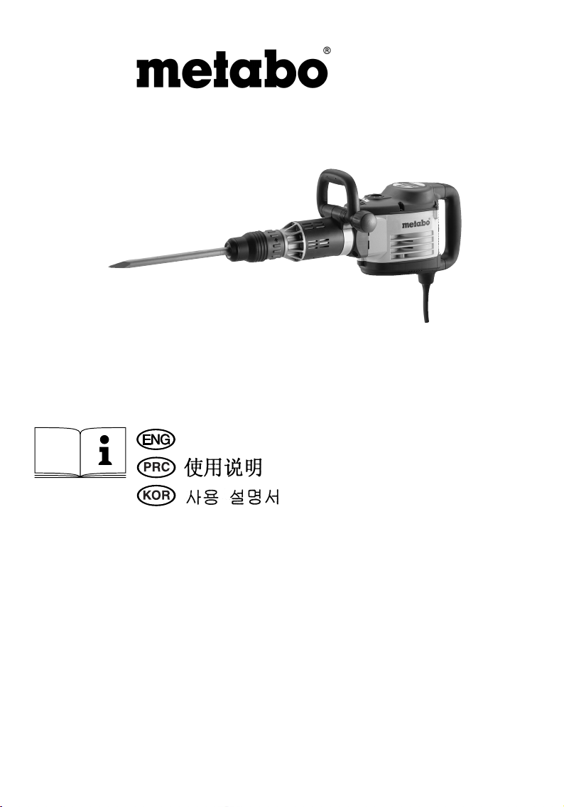
MHE 95
Made in Germany
Operating Instructions .................. page
..............................................
..........................................
170 26 7320 - 0506 (488682-03)
5
8
12
Page 2
MHE 95
SDS-max
UV110 230 240
IA15 8,5 8,5
P
1
W 1500
P
2
W 750
s
/min
bpm
1020-2040
WJ 5-25
C- 12
mkg (lbs) 9,8 (21.6)
a
hw
m/s
2
12,1
L
pA
dB (A) 88
L
WA
dB (A) 101
15
120
EN 60745,
98/37/EG, 89/336/EWG.
Dr. Johannes Haupt, Geschäftsführung
2005 Metabowerke GmbH,
Postfach 1229, 72602 Nürtingen, Germany
2
92
103
Page 3
X
1
2
3
4
5
6
7
8
9
3
Page 4
A
B
l
280 mm
400 mm
600 mm
280 mm
400 mm
600 mm
400 mm
300 mm
350 mm
300 mm
400 mm
C
CODE! Key
6.22500
6.31800
6.23351
6.23352
6.23358
6.23353
6.23354
6.23359
6.23355
6.23356
6.23366
6.23357
6.23367
b
- mm
25 mm
50 mm
80 mm
115 mm
26 mm
50 mm
b
l
4
Page 5
Operating Instructions
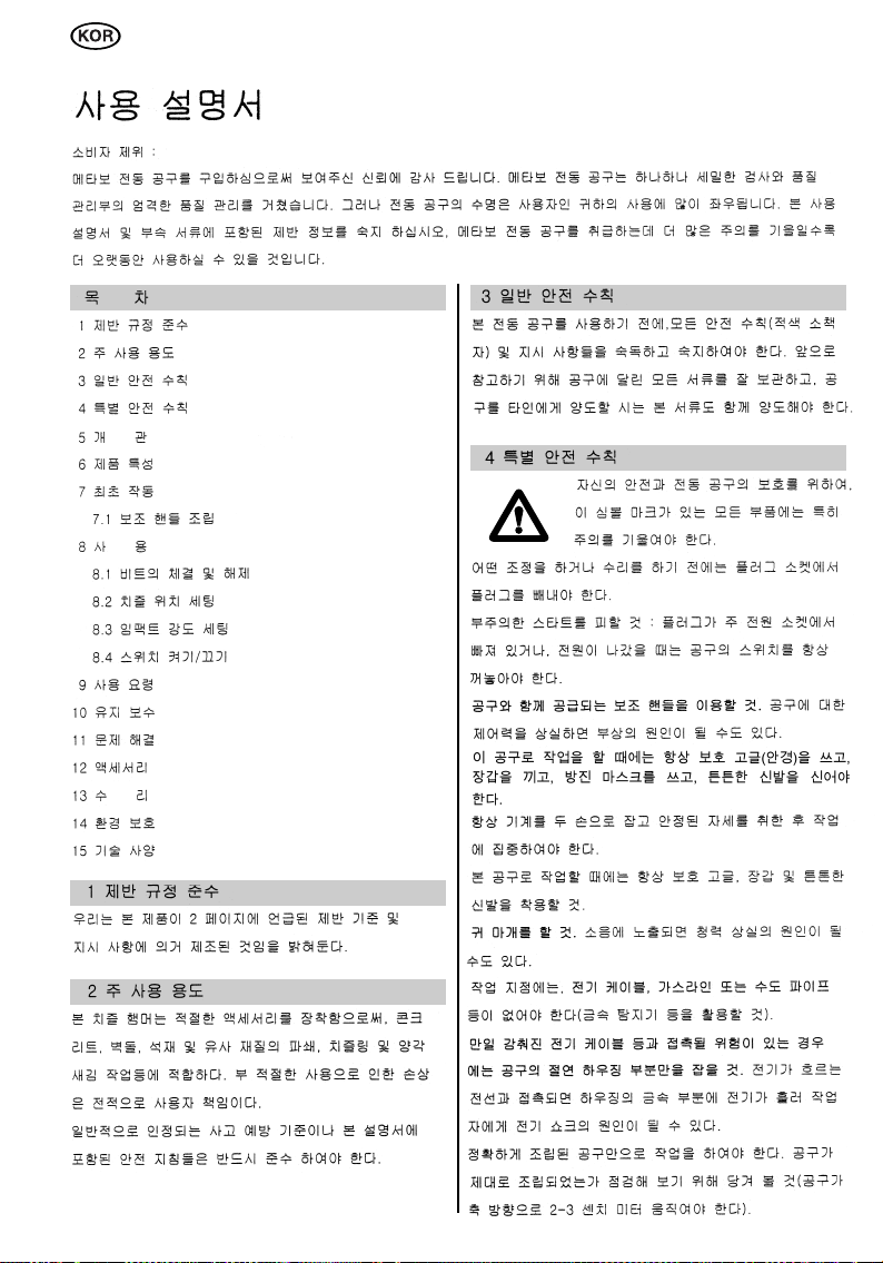
Dear Customer,
Thank you for the trust you have placed in us by buying a Metabo power tool. Each Metabo power tool
is carefully tested and subject to strict quality controls by Metabo’s quality assurance. Nevertheless, the
service life of a power tool depends to a great extent on you. Please observe the information contained
in these instructions and the enclosed documentation. The more carefully you treat your Metabo power
tool, the longer it will provide dependable service.
Contents
1 Declaration of Conformity
2 Specified Conditions of Use
3 General Safety Instructions
4 Special Safety Instructions
5Overview
6 Special Product Features
7 Initial Operation
7.1 Assembly of the additional handle
8Use
8.1 Positioning, removing tool
8.2 Setting chisel position
8.3 Setting impact force
8.4 Switching on and off
9 Tips and Tricks
10 Servicing
11 Troubleshooting
12 Accessories
13 Repairs
14 Environmental Protection
15 Technical Specifications
1 Conformity Declaration
We, being solely responsible, hereby declare that
this product conforms to the standards and directives specified on page 2.
2 Specified Use
The chisel hammer, with suitable accessories, is
suitable for heavy demolition work, chiselling and
embossing in concrete, brick, stone and similar
materials.
The user bears sole responsibility for damage
caused by improper use.
Generally accepted accident prevention regulations and the enclosed safety information must be
observed.
3 General Safety Instructions
Before using this power tool, carefully read
through and familiarise yourself with all the
enclosed safety information (red booklet) and the
instructions. Keep all enclosed documentation for
future reference, and pass on your power tool only
together with this documentation.
4 Special Safety Instructions
For your own protection and for the
protection of your power tool pay
attention to all parts of the text that
are marked with this symbol!
Pull the plug out of the plug socket before any
adjustments or servicing are performed.
Avoid inadvertent starts: always switch the tool off
when the plug is removed from the mains socket or
if there has been a power cut.
Use the additional handles supplied with the
tool.
Loss of control can lead to injuries.
Always hold the machine with both hands at the
intended handles, take a secure stance and
concentrate on the work.
Always wear protective goggles, gloves, and
sturdy shoes when working with this tool.
Wear ear protectors.
Wear ear protectors.
cause loss of hearing.
cause loss of hearing.
Ensure that the spot where you wish to work is free
Ensure that the spot where you wish to work is free
power cables, gas lines or water pipes
of
power cables, gas lines or water pipes
of
using a metal detector).
using a metal detector).
Hold the power tool only at insulated housing
Hold the power tool only at insulated housing
parts if there is any danger of making contact
parts if there is any danger of making contact
with concealed electric cables or the supply
with concealed electric cables or the supply
cable.
Contact with live wires energises the metal
cable.
Contact with live wires energises the metal
parts of the housing and can cause electric shock
parts of the housing and can cause electric shock
to the operator.
to the operator.
Work only with a correctly positioned tool. Pull on
Work only with a correctly positioned tool. Pull on
the tool to check that it is correctly seated. (The
the tool to check that it is correctly seated. (The
tool must move a few centimetres in axial direc-
tool must move a few centimetres in axial direc-
tion.)
tion.)
In cold weather, or if the tool has not been used for
In cold weather, or if the tool has not been used for
a long time, run the tool for a few minutes without
a long time, run the tool for a few minutes without
load before using.
load before using.
Exposure to noise can
Exposure to noise can
(e.g.
(e.g.
5
Page 6
Before plugging in, check to see that the
rated mains voltage and mains
frequency, as stated on the rating label,
match with your power supply.
Use only approved extension cables, model
H07RN, with a min. cross-section of 1.5 mm
2
.
Extension cables must correspond to the power
consumption of the machine (cf Technical Specifications). If a cable roller is used, always roll up the
cable completely.
7.1 Assembly of the additional handle
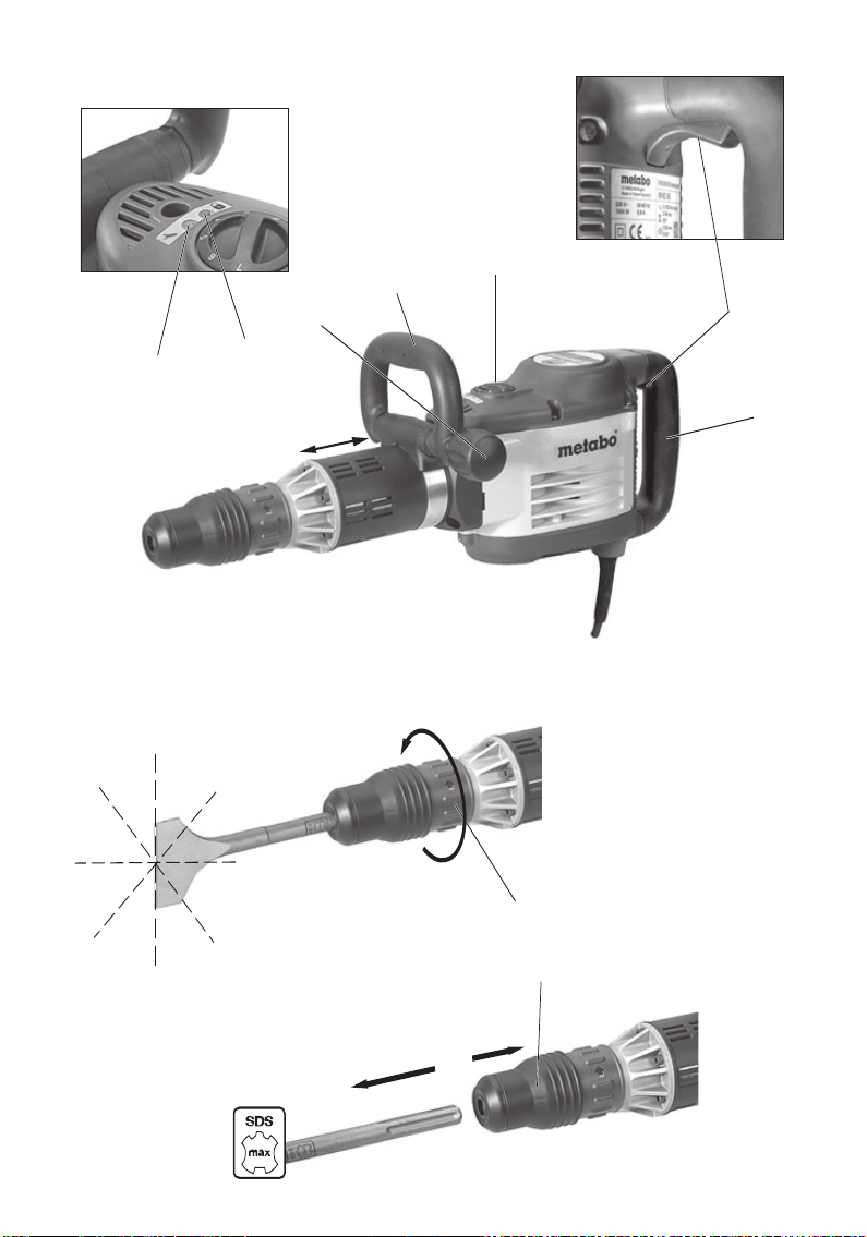
For safety reasons, always use the additional handle (4) supplied.
Open the clamping ring by turning the clamping
knob (5) to the left and push onto the collar of the
tool. The additional handle can be fitted in area X
in any desired position or at any angle. Tighten the
clamping knob firmly.
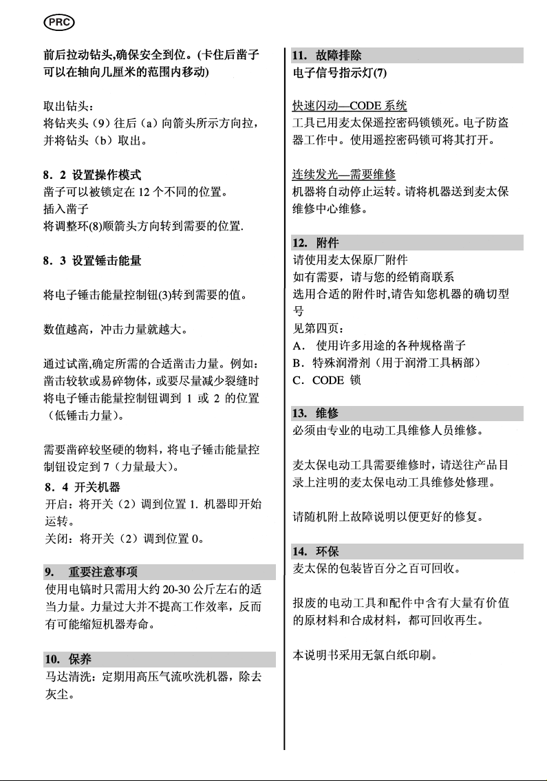
8.1 Positioning, removing tool
Before inserting, clean tool shank and
apply supplied special grease (accessories: Order no. 6.31800)!
Use only SDS-max tools.
Positioning tool:
Turn tool and insert until it engages. The tool is
locked automatically.
Pull on the tool to check that it is
correctly seated.
(The tool must move a
few centimetres in axial direction.)
Removing the tool:
Pull tool lock (9) to the rear (a) in direction of arrow
and remove tool (b).
8.2 Setting chisel position
The Chisel can be locked in 12 different positions.
Insert the chisel.
Turn the adjusting ring (8) in the direction of the
arrow until the chisel is in the desired position.
8.3 Setting impact force
Turn the impact force controller (3) to the desired
value.
The higher the number, the greater the impact
force.
7 Commissioning
8Use
When working above ground level, ensure that the
area below you is clear.
Never touch the chisel or parts near the chisel
directly after work because they may be extremely
hot and can cause burns to the skin,
Always route the connecting cable away from the
tool towards the rear.
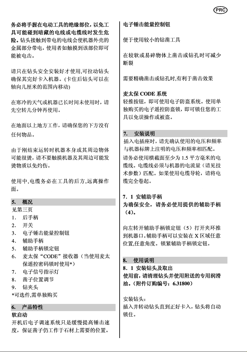
See page 3 (please unfold).
1 Rear handle
2 On/off switch
3 Electronic impact force controller
4 Additional handle
5 Clamping knob
6 Receiver of
Metabo CODE! Systems
(for use with
a
Metabo CODE! Key * )
7 Electronic signal indicator
8 Adjusting ring for chisel position
9 Tool lock
* not in scope of delivery
Smooth start:
The electronics system only increases impact
speeds slowly after switching on so that the chisel
retains the desired position on the masonry.
Electronic impact force controller:
Also allows the use of smaller tools.
To reduce cracking when chiselling in soft and
brittle materials.
To produce an optimised tool setting for extremely
precise chiselling.
5Overview
6 Special Product Features
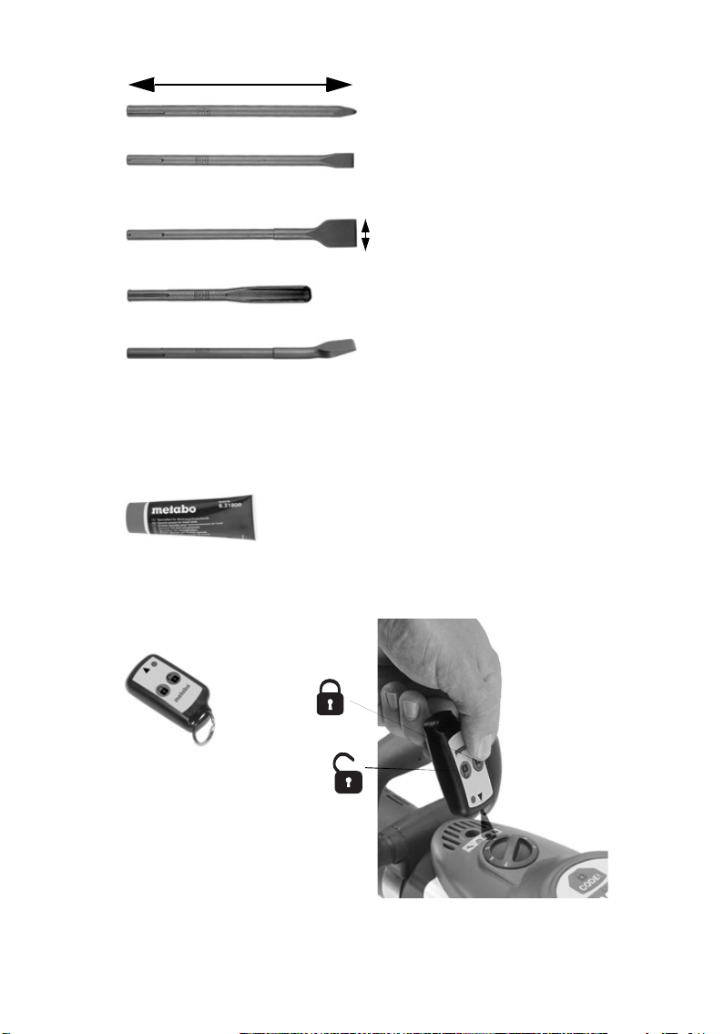
Metabo CODE! System
Electronic anti-theft device at the push of a button.
With the CODE! key, which is available separately,
you can lock up your power tool and thus protect
it against misuse or theft.
6
Page 7
Wear ear protectors!
ahw = Typical estimated acceleration in the
hand/arm area
Measured values determined in conformity with
EN 50144.
The technical specifications quoted are subject to
tolerances (in compliance with the relevant valid
standards).
S
Repairs to electrical tools must be carried out by
qualified electricians ONLY!
Any Metabo power tool in need of repair can be
sent to one of the addresses listed in the spare
parts list.
Please enclose a description of the fault with the
power tool.
Metabo's packaging can be 100% recycled.
Scrap power tools and accessories contain large
amounts of valuable resources and plastics that
can be recycled.
These instructions are printed on chlorine-free
bleached paper.
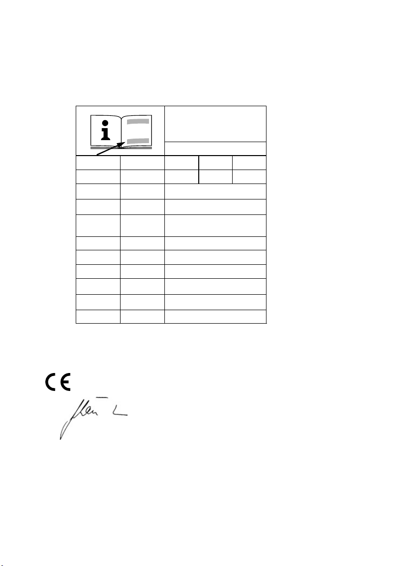
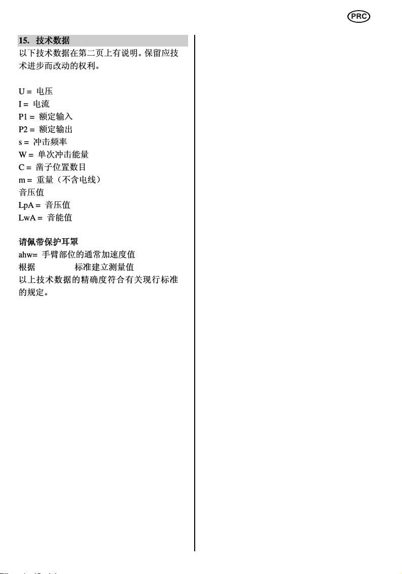
Explanatory notes on the specifications on page 2.
Changes due to technological progress reserved.
U = Voltage
I=Current
P
1
= Nominal power input
P
2
= Power output
s = Impact frequency
W = Single impact force
C = Number of chisel positions
m = Weight without mains cable
Typical A-effective perceived sound levels:
LpA = Sound pressure level
L
WA
= Acoustic power level
13 Repairs
14 Environmental Protection
15 Technical Specifications
Rapid flashing - CODE! System
The tool was locked with a CODE! Key. The electronic anti-theft device is active. The tool can be
unlocked again with a CODE! key.
Continuous light - Service call-up
The tool cut out automatically. Bring the tool to a
Metabo Service Centre.
f
Use only genuine Metabo accessories.
If you need any accessories, check with your
dealer.
For dealers to select the correct accessory, they
need to know the exact model designation of your
power tool.
See page 4:
A Extensive range of chisels for a wide variety of
applications.
B Special grease (for lubricating the tool shanks)
12 Accessories
set the impact force controller to "1“ to "2“ (low
impact force).
To break harder materials, set the impact force
controller to "7" (top power).
8.4 Switching On and Off
Switching on:
set the on/off switch (2) to
position 1. The tool now runs in continuous operation.
Switching off:
set the on/off switch (2) to
position 0.
When working with the chisel hammer, only a
moderate amount of press-on pressure (20 - 30
kg). High press-on pressure does not increase
work capacity and can possibly shorten the
service life of your tool.
Motor cleaning: blow out the machine regularly
and thoroughly through the air slots with
compressed air.
Electronic signal indicator (7):
9 Tips and Tricks
10 Maintenance
11 Troubleshooting
The correct setting is found by trial and error.
Example: if soft, brittle materials are being
chiselled, or crackin
g
is to be kept to a minimum,
C CODE! key
EN 60745.
7
Page 8
8910
Page 9
Page 10
Page 11
EN 60745
11
Page 12
121314
Page 13
Page 14

Page 15

Page 16
EN 60745
 Loading...