

Page 1
D
Betriebsanleitung Kompressor
GB
Operating Instructions Air Compressor
D
Achtung! Lesen Sie diese Anleitung vor der Installation und Inbetriebnahme aufmerksam durch.
GB
Attention! Carefully read through these instructions prior to installation and commissioning.
115 163 8437 / D/GB / 2203 - 2.3
Page 2

Inhaltsverzeichnis
1 Allgemeines
2Sicherheitshinweise
3 Einsatzbereiche
4 Produkthaftung/Garantie
5 Aufstellung
6Inbetriebnahme/Betrieb
6.1 Allgemein
6.2 Lastfreier Anlauf
6.3 Verlängerungskabel
6.4 Motorschutzschalter
7 Druckwächter
8 Wartung
8.1 Luftfilter
8.2 Schmierung
8.3 Kondensatentleerung
8.4 Keilriemenantrieb
8.5 Zylinderkopfschrauben
8.6 Wartungstabelle
9 Betriebsstörungen
9.1 Luftverlust
9.2 Zu häufiges Anlaufen
9.3 Defekt am Rückschlagventil
9.4 Defekt am Entlastungsventil
9.5 Ventilschäden am Aggregat
9.6 Abschaltung durch Motorschutzrelais
10 Wirkungsweise der Sicherheitseinrichtung
11 Unfallverhütungsvorschriften
12 Pflichten des Betreibers nach Inbetriebnahme
13 Sachkundig ist nur wer ...
14 Technische Daten
15 Gebrauchstabelle
1 Allgemeines
Vor Inbetriebnahme der Kompressoranlage ist die beiliegende Betriebsanleitung durchzulesen und zu beachten,
da bei Schäden und Betriebsstörungen, die durch unsachgemäße Behandlung hervorgerufen werden, keine
Gewährleistung übernommen wird.
D
2 Sicherheitsanweisungen
- Vor dem Beginn der Arbeit stets eine Vorbetriebsprüfung durchführen und den ordnungsgemäßen Zustand
des Kompressors feststellen.
- Den Kompressor während des Betriebs mindestens 1 m von Gebäuden oder anderen Maschinen aufstellen.
- Den Kompressor auf einer ebenen Fläche aufstellen.
- Lernen Sie, wie man den Kompressor sofort anhalten kann und machen Sie sich mit allen Bedienelementen
vertraut. Erlauben Sie niemandem, den Kompressor ohne entsprechende Unterweisung zu bedienen.
- Während des Betriebs sind Kinder und Haustiere vom Kompressor fernzuhalten.
- Bei einer inkorrekten Handhabung besteht die Gefahr eines elektrischen Schlages; den Kompressor nie mit
nassen Händen bedienen.
- Den Kompressor unbedingt vor Frost schützen, da ansonsten der Verdichter oder der Druckluftbehälter
Schaden nehmen kann.
- Gekapselte Kompressoren dürfen nur mit geschlossenem Gehäuse betrieben werden.
- Es ist darauf zu achten, daß Sicherheitsrelevante Teile wie Luftanschlußfilter und Druckentlastungseinrichtungen nicht durch Verschmutzung in ihrer Funktion eingeschränkt wird.
3 Einsatzbereiche
Der Kompressor dient zur Drucklufterzeugung, die für druckluftbetriebene Werkzeuge, Hub- und Steuereinrichtungen, z.B. Werkzeugmaschinen, und allgemeine Anwendung benötigt werden.
4 Produkthaftung/Garantie
Nicht aufgeführte Arbeiten und Einsatzmöglichkeiten bedürfen der schriftlichen Genehmigung der Firma
Elektra Beckum AG, Postfach 1352, D-49703 Meppen.
Jeder Maschine und dem Maschinenzubehör ist eine Garantiekarte beigefügt.
Zur Wahrung Ihres Garantieanspruches und im Interesse der Produktsicherheit achten Sie bitte darauf, daß die
Garantiekarte sofort beim Kauf ausgefüllt und die Antwortkarte ans Werk geschickt wird.
Bitte melden Sie sich bei Garantieansprüchen bei Ihrem Fachhändler.
Garantiearbeiten werden grundsätzlich durch uns oder von uns autorisierten Servicestellen durchgeführt.
Außerhalb der Garantiezeit können Sie Reparaturen durch entsprechende Fachfirmen ausführen lassen.
Bitte Reparaturrechnungen verwahren! Technische Änderungen vorbehalten!
5 Aufstellung
Der Kompressor ist zur Aufstellung auf waagerechter Fläche vorgesehen. Die Verbindung mit Verbrauchern muß
durch elastische Bindeglieder überbrückt werden.
Der Hubkolbenverdichter entwickelt beim Betrieb durch den Verdichtungsprozeß Wärme, welche vorrangig
durch Wärmestrahlung und Konvektion abgeführt wird. Je nach Betriebs- und Aufstellungsbedingungen wird die
maximale Drucklufttemperatur erreicht.
Achten Sie deshalb beim Aufbau und während des Betriebes auf die Realisierung der erforderlichen Kühlung.
Nur auf diese Weise sichern Sie sich einen ausfallfreien Betrieb der Arbeitsventile über einen langen Zeitraum.
Der Abstand zu einer Wand oder ähnlichem muß mindestens 1 m betragen.
2
Page 3

6 Inbetriebnahme/Betrieb
6.1 Allgemein
Prüfen Sie, ob beim Transport Armaturen oder sonstige Teile beschädigt sind.
Stationäre Kompressoren werden ohne Kraft-
Anschlußschema nur für diesen Elektra Beckum Motor
stecker ausgeliefert.
Der Anschluß darf nur von einem ElektroFachmann vorgenommen werden.
Der gelb-grüne Schutzleiter darf nur an den
durch Erdungszeichen gekennzeichneten Kontakt im Stecker angeschlossen
werden.
Schutzleiter gelb-grün
Phase L1 schwarz
Phase L2 braun
Phase L3 blau
Bei Drehrichtungsänderung Phase L1 mit L2 im Stecker tauschen.
Netzkabel von der Maschine kommend
Fahrbare Kompressoren werden serienmäßig mit einem Kraftstromstecker ausgerüstet. Vor Inbetriebnahme
muß die Drehrichtung überprüft werden indem der Kompressor kurz gestartet wird.
Eine Drehrichtungsänderung darf nur von einer Elektrofachkraft vorgenommen werden.
Die Absicherung muß 16 Amp. träge sein.
6.2 Lastfreier Anlauf
Elektra Beckum Kompressoranlagen werden mit automatischer Entlastung geliefert. Das Entlastungsventil ist
am Druckschalter angebaut. Es wird beim automatischen Abschalten der Anlage mechanisch betätigt. Durch die
Entlastung wird die Druckleitung zwischen Verdichter und Rückschlagventil nach dem Ausschalten entleert. Ein
lastfreier Anlauf ohne Gegendruck ist somit gewährleistet.
6.3 Verlängerungskabel
Damit ein einwandfreier Betrieb auf Baustellen gewährleistet ist, müssen die Verlängerungskabel einen
Querschnitt von mind. 2,5 mm2 haben.
6.4 Motorschutzschalter
Sollte die Luftkompressoranlage über das Motor-Schutzrelais abgeschaltet werden, muß überprüft werden, ob
Fehlerquellen vorliegen, die zu beachten sind.
Als Ursache kommen folgende Punkte in Frage:
1. Mangelhafte Stromversorgung, Unterspannung der E-Versorgung oder Spannungsabfall durch ungeeigne-
tes Verlängerungskabel.
2. Niedrige Umgebungstemperatur, die durch zähen Ölfilm schwergängigen Anlauf zur Folge hat. Evtl. Ölsorte
zu dickflüssig.
3. Überlastung der Anlage durch Dauerlauf unter Vollastbedingungen.
4. Bei defekter, automatischer Entlastung läuft der Luftkompressor nicht lastfrei an. Es ist zu kontrollieren, ob
die Anlage beim Ausschalten selbsttätig entlüftet.
5. Ist die Temperatur der Relais abgesunken, kann der Kompressor erneut gestartet werden.
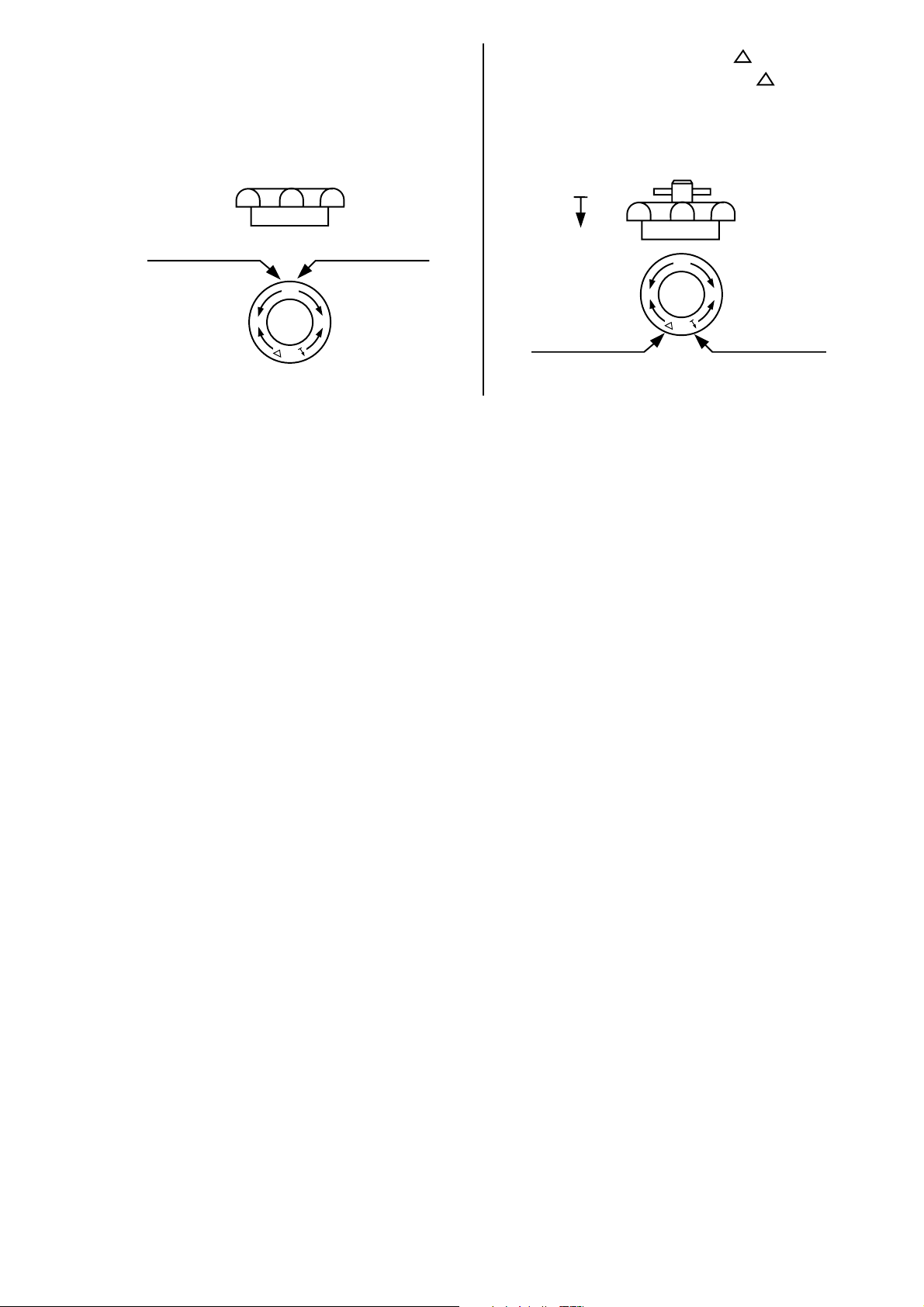
7 Druckwächter
Die automatischen Druckschalter der Anlagen werden im Werk auf einen bestimmten Ein- und Ausschaltdruck
einreguliert.
Soll der Druckwächter auf andere Werte eingestellt werden, so ist das im Schalter liegende Merkblatt zu
beachten.
Druckeinstellung (nur unter Druck vornehmen) Einstellbereich
-
+
-
+
Einschaltdruck Ausschaltdruck
Type Pa (bar)
Unterer Druckwert
Pe (bar) min/max
MDR 2/6 ◊ 0.6 1.5 ÷ 3.5
◊ 4.7 6.0 ÷ 8.0
I
Draufsicht
0
Ein/Aus-Schalter
MDR 2/11 ◊ 2.7 4.0 ÷ 6.0
◊ 9.2 11.0 ÷ 13.0
3
Page 4
Ausschaltdruck P
Cut-off pressure P
Druckdifferenz P
Pressure differential P
geringer:
lesser:
niedriger:
lower:
Handrad nach
links drehen
turn knob
counter-clockwise
P
+–
P
höher:
higher:
Handrad nach
rechts drehen
turn knob
clockwise
und nach
rechts drehen
and turn
clockwise
Handrad herunterdrücken
press knob down
P
und nach
+–
links drehen
P
Spindel darf sich nicht mitdrehen
Spindle must be disengaged
and turn
counter-clockwise
8 Wartung
8.1 Luftfilter
Ansaugfilter bei jedem Ölwechsel, bei staubigem Betrieb häufiger, auswaschen und bis zur Trocknung
ausblasen.
Staubfreie Saugluft verlängert die Lebensdauer des Kompressors. Je nach Verschmutzungsgrad der Saugluft
sind die Filter in Abständen von ca. 2 - 8 Wochen zu säubern. Luftfilter abnehmen, ausklopfen und mit
Waschbenzin auswaschen. Anschließend ausblasen. Bei starker Verschmutzung ist der Filter zu wechseln.
größer:
greater:
8.2 Schmierung
Bei Erstinbetriebnahme ist nach ca. 100 Betriebsstunden ein Ölwechsel vorzunehmen. Danach etwa alle 300
Betriebsstunden.
Zum Ölwechsel wird der Ölmeßstab und die Ölablaßschraube herausgeschraubt und das Altöl restlos
abgelassen.
Ölstand täglich kontrollieren.
Der maximale Ölstand muß in der Mitte des Ölschauglases sein.
Kompressoranlagen werden mit Öl angeliefert. Kontrollieren Sie trotzdem bei Inbetriebnahme und in regelmäßigen Abständen den Ölstand. Bei Kompressoren mit Ölmeßstab sollte sich der Ölstand zwischen der Minimum
und Maximum Markierung befinden. Wir empfehlen die Verwendung von Elektra Beckum Schmierstoffen. Es
können auch Motorenöle im Bereich von HD 20 bis 30 eingesetzt werden. Ölmangel führt zu Verschleißschäden.
Zu hoher Ölstand ergibt unsaubere Druckluft und führt zu Verschmutzung der Ventile (Leistungsabfall) und der
Anlage.
8.3 Kondensatentleerung
Kondenswasserentleerung muß täglich durch das Entwässerungsventil vorgenommen werden. (Rändelschraube wieder fest anziehen).
Das im Druckbehälter angesammelte Kondensat ist in regelmäßigen Zeitabständen zu entleeren. Die Menge der
Kondensatausscheidungen richtet sich nach der Luftfeuchtigkeit und den Betriebsbedingungen und ist bei hoher
Umgebungstemperatur sowie bei starker Belastung wesentlich höher als bei niedriger Belastung und kühler
Umgebungstemperatur. Es ist unbedingt darauf zu achten, daß die Anlage kühle Luft ansaugt und die warme
Kühlluft abgeführt wird. Der Kompressor ist in trockenen und frostfreien Räumen zu installieren.
Achtung! Bei Temperaturen unter 0° C gefriert das Kondensat und es können erhebliche Folgeschäden
entstehen.
Das Kondensat ist ölhaltig und darf nur mit entsprechendem Ölabscheider entsorgt werden.
8.4 Keilriemenantrieb
Der Keilriemenantrieb ist auf eine kraftschlüssige Verbindung zu überprüfen und evtl. nachzuspannen.
8.5 Zylinderkopfschrauben
Die Zylinderkopfschrauben müssen nach ca. 50 Betriebsstunden nachgezogen werden.
4
Page 5

8.6 Wartungstabelle
täglich 50 Stunden 100 Stunden 300 Stunden
Ölstand prüfen X
Ölwechsel X
1)
Kondenswasser entleeren X
Ansaugfilter reinigen X
Zylinderkopfschrauben nachstellen X
1)
= Nach der 1. Inbetriebnahme
2)
= In staubiger Umgebung kürzere Intervalle
9 Betriebsstörungen
Vor der Ausführung von Wartung- und Reparaturarbeiten am Kompressor ist der Strom abzuschalten und der
Druck im Behälter restlos abzulassen. Bei Ersatzteilbestellungen ist der Kompressor-Typ und Modell anzugeben, damit Mißverständnisse vermieden werden.
9.1 Luftverlust
Luftverluste können von der schlechten Dichtung irgendeines Anschlusses herrühren. Diese Anschlüsse prüfen,
indem man sie mit Seifenwasser einpinselt.
9.2 Zu häufiges Anlaufen
Den Differenzdruck des Druckschalters erhöhen; wenn dies nicht genügt, bedeutet dies, daß die Liefermenge
des Kompressors für den Verwendungszweck nicht geeignet ist.
9.3 Defekt am Rückschlagventil
Der Kompressor bläst nach dem Abschalten durch den Entlüftungsstutzen oder durch die Entlüftungsbohrung
im Kurbelgehäuse ständig ab. Diese Störung wird durch verschmutzte oder verschlissene Dichtungen im
Rückschlagventil hervorgerufen. Der Druckbehälter ist zu entleeren. Danach das Rückschlagventil demontieren
und überprüfen.
Je nach Bedarf Dichtung erneuern oder reinigen.
X
2)
9.4 Defekt am Entlastungsventil
Der Kompressor bläst während des Laufens ständig über das Entlastungsventil am Druckwächter ab. In diesem
Fall liegt ein Schaden am Entlastungsventil vor.
9.5 Ventilschäden am Verdichter
Die Saug- und Druckventile im Zylinderkopf des Verdichters gehören zu den höchstbeanspruchten Teilen und
sind natürlichem Verschleiß unterworfen. Bei schadhaften Ansaugventilen tritt ein starker Leistungsabfall,
jedoch keine starke Erwärmung auf. Nach Abnehmen des Luftfilters kann man am Ansaugstutzen feststellen, ob
die angesaugte Luft teilweise oder ganz wieder ausgestoßen wird.
Bei Schäden an den Druckventilen macht sich ein Leistungsabfall bemerkbar, und die Anlage erreicht nur noch
einen Enddruck von ca. 2 - 4 bar.
Anlage unverzüglich stillegen. Ventil säubern, gegebenenfalls Ventilfedern und Ventilplatten erneuern.
Es ist darauf zu achten, daß evtl. Fremdkörper wie Späne und Ölkohle, die bei Ventilschäden in den
Verdichtungsraum gelangt sind, nach Abschrauben des Zylinderkopfes sorgfältig entfernt werden, da sonst
Kolben- und Zylinderschäden auftreten können.
9.6 Abschaltung durch Motorschutzrelais
Sollte die Kompressoranlage über das Motor-Schutzrelais abgeschaltet haben, muß vor dem Betätigen des
Einschaltdruckknopfes die Luft aus dem Druckbehälter abgelassen werden, damit ein leichter Anlauf gewährleistet ist. Grundsätzlich muß beim Ansprechen des Motorschutzschalters überprüft werden, ob Fehlerquellen
vorliegen, die zu beheben sind.
Als Ursache kommen folgende Punkte in Frage:
1. Mangelhafte Stromversorgung. Unterspannung der E-Versorgung oder Spannungsabfall durch ungeeigne-
tes Verlängerungskabel.
2. Niedrige Umgebungstemperatur, die durch zähen Ölfilm schwergängigen Anlauf zur Folge hat. Evtl. Ölsorte
zu dickflüssig.
3. Überlastung der Anlage durch Dauerlauf unter Vollastbedingungen.
4. Bei defekter, automatischer Entlastung läuft der Kompressor nicht lastfrei an. Es ist zu kontrollieren, ob die
Anlage beim Abschalten nach dem Erreichen des Enddruckes selbsttätig entlüftet.
5
Page 6

10 Wirkungsweise der Sicherheitseinrichtung
Das Sicherheitsventil ist ein federbelastendes Überstromventil, das bei einem evtl. Überdruck anspricht. Das
Sicherheitsventil schützt den Druckbehälter und den Verdichter vor unzulässiger hoher Druckbeanspruchung.
Da das Sicherheitsventil ein TÜV geprüftes Bauteil und für den zulässigen Betriebsdruck eingestellt ist, darf die
Plombe nicht beschädigt oder entfernt werden. (Siehe Druckbehälterverordnung, sowie TRB 403 und Unfallverhütungsvorschrift Verdichter VBG 16).
11 Unfallverhütungsvorschriften beachten!
Der Kompressor fällt in die Prüfungsgruppe III der Druckbehälterverordnung, wenn das Druckliterprodukt:
Maximaler Druck (in bar) x Kesselinhalt (in Liter) = weniger als 1000 ist.
Die Abnahmeprüfung für diesen Kompressor ist nur gültig, solange vom Betreiber keine Veränderung vorgenommen wird. Wird der Verdichter vom Betreiber verändert, so ist eine erneute Abnahme durch einen Sachverständigen notwendig. Nach dieser Abnahme bzw. Inbetriebnahme muß der Kompressor einer Prüfung, durch einen
Sachkundigen unterzogen werden.
Es muß in jedem Fall für eine wiederkehrende Prüfung durch einen Sachkundigen gesorgt werden.
Die Prüfintervalle sind entsprechend dem Einsatzfall so zu wählen, daß eine Gefährdung ausgeschlossen
werden kann (in der Regel reichen hier 2 Jahre aus).
Ist das Druckliterprodukt größer als 1000 muß die Anlage von einem Sachverständigen ( Sachverständiger
ist, wer nach § 24c, Abs. 1 und 2 der Gewerbeordnung ausgebildet ist (z.B. TÜV-Sachverständiger) abgenommen werden (in den meißten Fällen ist der TÜV zuständig).
Das hierfür erforderliche Baumustererzeugnis liegt dem Druckbehälter bei. Die Anmeldung zur Prüfung muß vom
Betreiber veranlaßt werden.
Folgende wiederkehrende Prüfungen müssen vom Betreiber veranlaßt werden:
nach 2 Jahren - äußere Prüfung
nach 5 Jahren - innere Prüfung
nach 10 Jahren - Druckprüfung
Jede Prüfung ist zu dokumentieren.
12 Pflichten des Betreibers nach Inbetriebnahme
Der Betreiber eines Druckbehälters hat diesen in ordnungsmäßigem Zustand zu erhalten, ordnungsgemäß zu
betreiben und zu überwachen. Er hat außerdem die notwendigen Instandhaltungs- und Instandsetzungsarbeiten
unverzüglich vorzunehmen und die den Umständen nach erforderlichen Sicherheitsmaßnahmen zu treffen.
Danach liegt die Verantwortung für den sicheren Betrieb von Druckbehältern eindeutig beim Betreiber. Er sollte
sich nicht darauf verlassen, daß Abnutzungen und andere Mängel sich bei Prüfungen zeigen.
Nähere Einzelheiten sind der Druckbehälterverordnung zu entnehmen. Sie kann unter der Bestell-Nr. ZH 1/400
vom Carl Heymann Verlag KG, Luxemburger Str. 449, 5000 Köln 41, bezogen werden. Die zugehörigen
technischen Regeln Druckbehälter (TRB) sind ebenfalls vom o. a. Verlag lieferbar.
13 Sachkundiger ist nur, wer
1. aufgrund seiner Ausbildung, seiner Kenntnisse und seiner durch praktische Tätigkeit gewonnenen Erfahrun-
gen die Gewähr dafür bietet, daß er die Prüfungen ordnungsgemäß durchführt.
2. die erforderliche persönliche Zuverlässigkeit besitzt,
3. hinsichtlich der Prüftätigkeit keinen Weisungen unterliegt,
4. falls erforderlich, über geeignete Prüfeinrichtungen verfügt und
5. durch die Bescheinigung über die erfolgreiche Teilnahme an einem staatlich anerkannten Lehrgang
nachweist, daß er die in Nummer 1 genannten Voraussetzungen erfüllt. Die Bescheinigung ist der
zuständigen Behörde auf Verlangen vorzulegen.
6
Page 7

14 Technische Daten
Top Line Geco 200/8/24 W Basic 240/8/24 W Basic Handy 240/8/3 W
Effektive Liefermenge 105 l/min 110 l/min 110 l/min
Ansaugleistung 190 l/min 220 l/min 220 l/min
Kompressordrehzahl 2850 U/min 2850 U/min 2850 U/min
Verdichter OL 200 D1 220 D1 220
Zylinder 1 1 1
Verdichterstufen 1 1 1
Motorleistung 1,1 kW 1,1 kW 1,1 kW
Nennspannung 230 V 230 V 230 V
Kesselinhalt 24 l 24 l 3 l
Betriebsdruck 8 bar 8 bar 8 bar
Maße 605x300x610 mm 645x335x620 mm 445x240x475 mm
Gewicht 27 kg 48 kg 18 kg
Schalleistungspegel LW
A
Aufstellung mobil mobil tragbar
Bestell-Nr. 023 002 0086 023 002 4073 023 002 4065
Ausstattung Mit Druckminderer Mit Druckminderer Mit Druckminderer
Top Line Basic 350/10/50 W Basic 350/10/50 D Basic 450/10/50 W
Effektive Liefermenge 142 l/min 142 l/min 172 l/min
Ansaugleistung 250 l/min 250 l/min 330 l/min
Kompressordrehzahl 1450 U/min 1450 U/min 1420 U/min
Verdichter B 2800 B 2800 B 2800/B
Zylinder 2 2 2
Verdichterstufen 1 1 1
Motorleistung 1,5 kW 1,5 kW 2,2 kW
Nennspannung 230 V 400 V 230 V
Kesselinhalt 50 l 50 l 50 l
Betriebsdruck 10 bar 10 bar 10 bar
Maße 838x370x698 mm 838x370x698 mm 820x440x710 mm
Gewicht 43 kg 43 kg 56 kg
Schalleistungspegel LW
A
Aufstellung mobil mobil mobil
Bestell-Nr. 023 003 5016 023 003 5032 023 004 5020
Ausstattung Mit Druckminderer Mit Druckminderer Mit Druckminderer
78 dB(A) 78 dB(A) 78 dB(A)
für konstanten für konstanten für konstanten
Arbeitsdruck. Arbeitsdruck. Arbeitsdruck.
TÜV-Abnahme TÜV-Abnahme TÜV-Abnahme
nicht erforderlich nicht erforderlich nicht erforderlich
88 dB(A) 88 dB(A) 87 dB(A)
für konstanten für konstanten für konstanten
Arbeitsdruck. Arbeitsdruck. Arbeitsdruck.
Komplett Komplett Komplett
TÜV-abgenommen TÜV-abgenommen TÜV-abgenommen
Top Line Classic 3000 Basic Euro
Effektive Liefermenge 110 l/min 110 l/min
Ansaugleistung 220 l/min 220 l/min
Kompressordrehzahl 2850 U/min 2850 U/min
Verdichter D1 220 D1 220
Zylinder 1 1
Verdichterstufen 1 1
Motorleistung 1,1 kW 1,1 kW
Nennspannung 230 V 230 V
Kesselinhalt 24 l 24 l
Betriebsdruck 8 bar 8 bar
Maße 645x335x620 mm 645x335x620 mm
Gewicht 48 kg 48 kg
Schalleistungspegel LW
A
99 dB(A) 99 dB(A)
Aufstellung mobil mobil
Bestell-Nr. 023 030 0003 023 002 2259
Ausstattung Mit Druckminderer Mit Druckminderer
für konstanten für konstanten
7
Arbeitsdruck. Arbeitsdruck.
TÜV-Abnahme TÜV-Abnahme
nicht erforderlich nicht erforderlich
Page 8

Top Line Basic 450/10/50 D Basic 500/10/60 D Power V2 400/10/24 W
Effektive Liefermenge 172 l/min 277 l/min 172 l/min
Ansaugleistung 330 l/min 482 l/min 345 l/min
Kompressordrehzahl 1420 U/min 1450 U/min 1450 U/min
Verdichter B 2800 B B 3900 NV34
Zylinder 2 2 V2
Verdichterstufen 1 1 1
Motorleistung 2,2 kW 3,0 kW 2,2 kW
Nennspannung 400 V 400 V 230 V
Kesselinhalt 50 l 60 l 24 l
Betriebsdruck 10 bar 10 bar 10 bar
Maße 820x440x710 mm 940x440x800 mm 638x370x698 mm
Gewicht 56 kg 66 kg 50 kg
Schalleistungspegel LW
A
87 dB(A) 90 dB(A) 87 dB(A)
Aufstellung mobil mobil mobil
Bestell-Nr. 023 004 5011 023 005 0015 023 004 0010
Ausstattung Mit Druckminderer Mit Druckminderer Mit Druckminderer
für konstanten für konstanten für konstanten
Arbeitsdruck. Arbeitsdruck. Arbeitsdruck.
Komplett Komplett Komplett
TÜV-abgenommen TÜV-abgenommen TÜV-abgenommen
15 Gebrauchstabelle
Classic
3000 /
Geco Basic Basic Power Basic Basic
200 240 350 V2 400 450 500
Basic
Euro
Ausblaspistole X X X X X X X
Pastengeberpistole DW 910 X X X X X X X
Handreifenfüllmesser X X X X X X X
Fettpresse DW 840 X X X X X X X
Kalkspritze LP X X X X X X X
Klammergerät DW 560 O X X X X X X
Klammergerät DW 570 O X X X X X X
Farbspritzpistole FB 1150 O X X X X X X
Karosseriesäge DW 2510 O O X X X X O
Drehschrauber DW 1610 O O X X X X O
Drehschrauber DW 1620 O O O X X X O
Unterbodenschutzpistole DW 810 O O O X X X O
Ölsprühpistole O O O O X X O
Farbspritzpistole Fließbecher FB 150 O O O X X O
Farbspritzpistole Saugbecher SB 200 O O O X X O
Meißelhammer DW 315S O O X
Schlagschrauber DW 120S O O X
Exzenterschleifer DW 640 K O O
Schwingschleifer DW 650 O O
Sandstrahlpistolenset O O
Stabschleifer DW 610 O O
Stabschleifer DW 620 S O O
Stichsäge DW 510 O O
Bohrmaschine DW 1510 O O
Farbspritzpistole FB 2150 O O
X = Dauereinsatz O = Kurzzeiteinsatz
8
Page 9

Contents
1 General Information
2 Safety Information
3 Application
4 User Responsibility
5 Installation
6 Commissioning/Operation
6.1 General
6.2 Relief Starting
6.3 Extension Cables
6.4 Motor Protection Relay
7 Automatic Pressure Switch
8 Service And Maintenance
8.1 Air Intake Filter
8.2 Lubrication
8.3 Condensate Draining
8.4 V-Belt Drive
8.5 Cylinder Head Bolts
8.6 Service Intervals
9 Operating Failures
9.1 Air Loss
9.2 Compressor Starts Too Often
9.3 Faulty Return Valve
9.4 Faulty Relief Valve
9.5 Faulty Suction/Pressure Valves
9.6 Tripped Motor Protection Relay
10 Operation Of The Safety Valve
11 Regulations For The Prevention Of Accidents
12 User Responsibility After Commissioning
The Compressor Unit
13 A competent specialist is, who ...
14 Specifications
15 Utility Table
2 Safety Information
- Carry out a preoperation check prior to any operation of the compressor to ensure that it is in proper operating
condition.
- When running keep the compressor at a distance of at least 1 meter from buildings and other machinery.
- Set up the compressor unit on a firm and level ground.
- Learn how to stop the compressor immediately in cause of an emergency. Become familiar with all control
elements. Do not permit other persons to operate the compressor without being familiar with its control
elements.
- When running, keep children and pets at a safe distance from the compressor unit.
- Risk of electric shock from improper handling; never operate the compressor with wet hands.
- Keep unit from freezing; both the pump and the pressure vessel may be damaged by frost.
- Encapsulated compressor units should be operated only with their housing fully closed.
- Make sure that the function of safety relevant parts such as safety valves, pressure regulators and filters is
not impaired by soiling.
GB
3 Application
This compressor unit is intended for generating compressed air, required for pneumatic lifting and control
devices, pneumatic tools and general use.
4 User Responsibility
This machine will perform in conformity with the description contained in the instructions provided. This machine
must be checked periodically. Defective equipment (including power cables) should not be used. Parts that are
broken, missing, obviously worn, distorted or contaminated, should be replaced immediately. Should such repair
or replacement become necessary, it is recommended that such repairs are carried out by qualified persons
approved by Elektra Beckum or its representatives.
This machine or any of its parts should not be altered or changed from standard specifications. The user of this
machine shall have the sole responsibility for any malfunction which results from improper used or unauthorized
modification from standard specifications, faulty maintenance, damage or improper repair by anyone other than
qualified persons approved by Elektra Beckum or its representatives.
Elektra Beckum reserves the right to change specifications and design without prior notice and without
incurring obligation of any kind.
Equipment referred to as available or optional may be at extra cost.
5 Installation
This compressor unit is intended for horizontal, level installation. Connections to distribution systems or tools
must be made by flexible links, e.g. air hose of suitable dimension.
During operation the reciprocating piston compressor generates heat by the compression process, which is
dissipated primarily by radiation and convection. Depending on operating and installation conditions the
maximum compressed air temperatur is reached. It is therefore important to realize sufficient cooling when
installing the unit, in order to have sufficient air ventilation for cooling when the compressor unit is operating. This
ensures a long service life of the cylinder head valves. The distance between the compressor unit and a wall or
similar obstruction should not be less than 1 meter.
9
Page 10
6 Commissioning/Operation
6.1 General
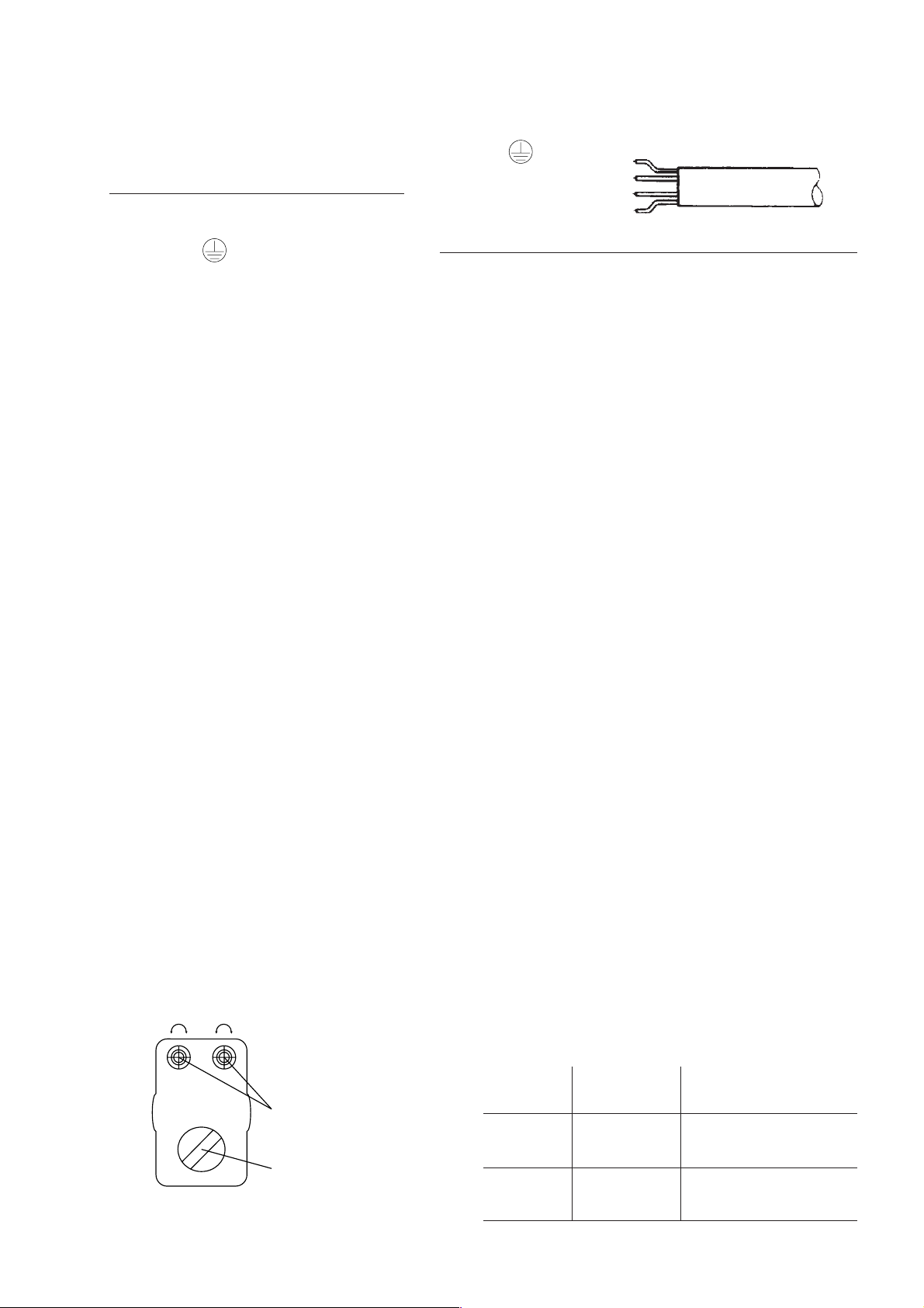
● Check armatures, fittings and pipes for transport damage.
Stationary units are supplied without a plug
Electrical connection for this Elektra Beckum motor only
on the power cable.
Connection to a supply circuit should be
made only by a qualified electrician.
The yellow/green earth lead must only be
connected to the earth lead terminal in the
Earth lead yellow/green
Phase L1 black
Phase L2 brown
Phase L3 blue
power cable
plug marked .
Interchange L1 and L2 to change direction of rotation.
Mobile compressor units are supplied with a CEE type 5-pin industrial plug. Check direction of rotation by starting
the unit briefly.
Changing the direction of rotation should only be undertaken by a qualified electrician.
Connect to a circuit protected by 16 A time-lag fuses or miniature circuit breakers.
6.2 Relief Starting
Elektra Beckum compressor units are supplied with automatic pressure relief. The relief valve is fitted on the
automatic pressure switch. It is mechanically actuated when the pressure switch switches the compressor off.
This feature relieves the pressure from the pressure line between the pump and the pressure vessel, thus
assuring a load-free starting without counter pressure.
6.3 Extension Cables
Extension cables must have a minimum conductor crossection of 2.5 mm2.
6.4 Motor Protection Relay
If the motor protection relay has tripped, a fault situation has developed. The cause can be one of the following:
1. Inferior power supply, brown-out in the supply system or voltage drop caused by unsuitable extension cable.
2. Low ambient temperature, reducing the crankcase oil's viscosity, increasing the torque load on startup.
Change to oil with higher viscosity.
3. Overload of the unit due to continuous operation under full load.
4. With a faulty automatic relief valve the pump has to start against counter pressure. Check if the pressure line
is vented when the compressor pump stops.
5. Restart compressor after the motor protection relay has cooled down.
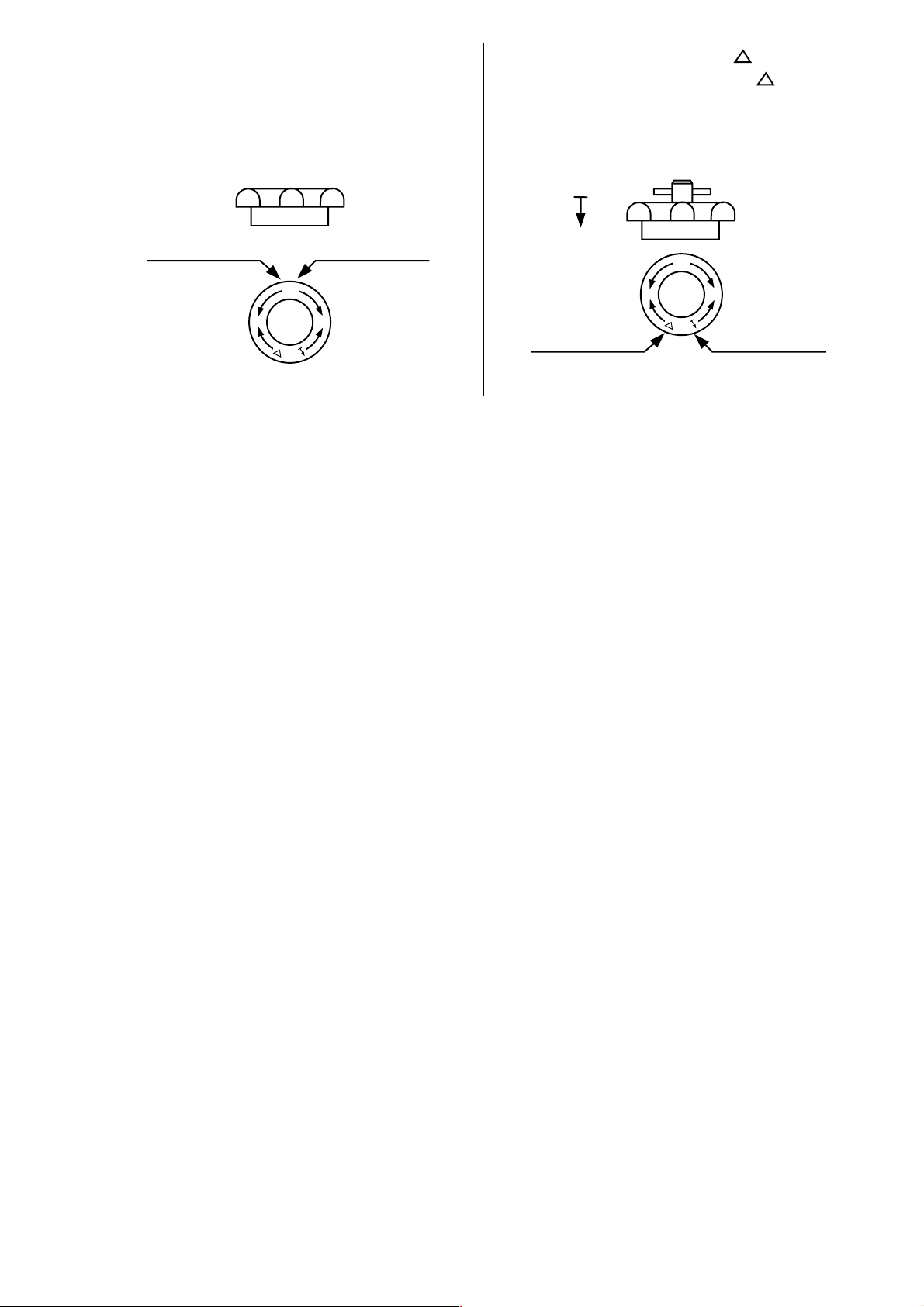
7 Automatic Pressure Switch
The automatic pressure switch is factory-set to a certain to specific minimum and maximum pressure, at which
the pressure switch will switch the power for the motor on or off.
If the pressure switch needs to be set to different values, refer to the instructions supplied with the pressure switch.
Pressure setting (set only when under pressure) Setting range
-
+
-
+
Cut-in Pressure Cut-out pressure
Model Pa (bar)
Startup pressure
Pe (bar) min/max
MDR 2/6 ◊ 0.6 1.5 ÷ 3.5
◊ 4.7 6.0 ÷ 8.0
I
Top view
0
On/off switch
MDR 2/11 ◊ 2.7 4.0 ÷ 6.0
◊ 9.2 11.0 ÷ 13.0
10
Page 11
Ausschaltdruck P
Cut-off pressure P
Druckdifferenz P
Pressure differential P
geringer:
lesser:
niedriger:
lower:
Handrad nach
links drehen
turn knob
counter-clockwise
P
+–
P
höher:
higher:
Handrad nach
rechts drehen
turn knob
clockwise
und nach
rechts drehen
and turn
clockwise
Handrad herunterdrücken
press knob down
P
und nach
+–
links drehen
P
Spindel darf sich nicht mitdrehen
Spindle must be disengaged
and turn
counter-clockwise
8 Service And Maintenance
8.1 Air Intake Filter
Wash air filter element at each oil change, more often if compressor is operated in dusty environment. Blow out
with compressed air until dry.
Dust-free intake air extents the service life of the compressor pump. Depending on the degree of contamination
of the primed air the filter cartridge needs to be cleaned every 2-8 weeks. Remove filter element, tap to remove
loose dirt, and wash with naphta. Blow out until dry. If heavily soiled replace filter element.
größer:
greater:
8.2 Lubrication
First oilchange required after first 100 hours of operation, thereafter every 300 hours working hours.
To change oil, remove dipstick and drain plug on crankcase, let drain oil from crankcase completely.
Check oil level daily. It should be in the centre of the oil sight glass.
This compressor unit is shipped with oil filled into the crankcase. However, check oillevel prior to commissioning
the unit and in regular intervals thereafter. The oillevel must always be kept between the min. and max. marks
of the dipstick. We recommend to use Elektra Beckum approved lubricants or motor oil SAE 20/SAE 30. A low
oil level causes damage due to excessive wear. Too much oil causes oily air and soiling of the valves (loss of
performance).
8.3 Condensate Draining
Drain the condensate from the pressure vessel daily. The amount of condensate precipitation depends on the
ambient air temperature and operating conditions. A high ambient temperature and permanent running under full
load will produce more condensate than intermittend operation at low ambient air temperatures. It is important
that the pump is priming cool air and that the warmed up cooling air is led off. Install and operate the compressor
unit only in dry and frost-free environments.
Caution! At temperatures below freezing the condensate freezes, which could lead to substantial damage.
The condensate contains oil and may only be disposed off using an oil trap. If in doubt consult an Environment
Protection Agency officer for assistance.
8.4 V-Belt Drive
The v-belt drive needs to be checked regularly for a frictional connection. Tension belt if required.
8.5 Cylinder Head Bolts
Check and retighten cylinder head bolts every 50 hours of operation.
11
Page 12

8.6 Service Intervals
daily every 50 hrs. every 100 hrs. every 300 hrs.
Oillevel check X
Oil change X*
)
Drain condensate X
Clean airfilter element X
Retighten cylinder head bolts X
*)
= after initial operation
**)
= shorter intervals when operated in dusty environment
9 Operating failures
Always disconnect from power or open circuit breakers and relieve pressure from pressure vessel competely
before servicing. When ordering spare parts always state name of compressor unit, pump model, part number
and part name.
9.1 Air Loss
Loss of air is caused by leakages from air lines and hoses. Check fittings by applying soap water. The escaping
air will cause bubbles, clearly indicating the location of the leak.
9.2 Compressor Starts Too Often
Increase the differential pressure setting of the automatic pressure switch. If this does not help, the free air delivery
of the compressor pump is not sufficient for the application. Reduce air consumption or use a compressor with
a higher free air delivery.
X
**)
9.3 Faulty Return Valve
Worn gaskets or dirt in the return valve prevent its proper functioning. After the unit is switched off air escapes
through the vent port or breather bore of the crankcase. Caused by soiled or worn gaskets of the return valve,
keeping it from closing. Relieve air from pressure vessel. Disassemble the return valve and check. Clean or
replace gasket, as required.
9.4 Faulty Relief Valve
Constant air loss through relief valve at the automatic pressure switch. The relief valve is at fault. Replace solenoid
or the complete valve.
9.5 Faulty Suction/Pressure Valves
The suction and pressure valves in the pump's cylinder head belong to the most stressed parts of a compressor
and as such are subject to normal wear. Faulty or worn suction valves cause a considerable loss of performance,
without noticable heatup of the pump. Remove the air filter assembly to check if the primed air is partly or completly
ejected through the suction port.
Likewise with damaged pressure valves there is a performance loss, a maximum pressure of approx. only 4 - 6
bar is reached.
Stop compressor unit immediately. Take off the cylinder head and remove the valves. Clean valves, replace valve
springs and plates if required.
Make sure that all foreign matter like chips and oily carbon, which may have dropped into the cylinder from a faulty
valve, is carefully removed before the cylinder head is reinstalled, as otherwise there may be piston scuffing.
9.6 Tripped Motor Protection Relay
If the compressor unit was stopped by a tripped motor protection relay, the pressure must be released from the
pressure vessel before switching on again, to ensure load-free starting. Always check for the reason causing the
relay to trip and eliminate the fault situation. One or more of the following conditions may cause the motor
protection relay to trip:
1. Inferior power supply, brown-out in the supply system or voltage drop caused by unsuitable extension cable.
2. Low ambient temperature, reducing the crankcase oil's viscosity, increasing the torque load on startup.
Change to oil with higher viscosity.
3. Overload of the unit due to continuous operation under full load.
4. With a faulty automatic relief valve the pump has to start against counter pressure. Check if the pressure line
between the pump and the pressure vessel is vented when the compressor pump stops.
12
Page 13

10 Safety Valve Operation
The safety valve is a spring loaded relief valve, designed to protect the pressure vessel and pump from pressures
higher than the rated maximum operating pressure. It opens automatically if the pressure inside the pressure
vessel exceeds the rated pressure of the pump. The safety valve, being a principal safety component of a
compressor unit, is set to a specific pressure and tested by the Technical Safety Inspectorate (TÜV). Do not
damage or remove the seal from it, this invalidates the manufacturer warranty.
11 Regulations For The Prevention Of Accidents
Know the local safety regulations for the operation of compressor units and pressure vessels.
For all Elektra Beckum compressor units an individual type examination has been carried out in compliance with
regulations in force in Germany at the time of manufacture. However, it is the resonsibility of the operator of the
compressor unit to have it tested, inspected and approved according to the regulations applicable and in force
at the place of operation, to ensure operation in compliance with these regulations.
12 User Responsibility After Commissioning The Compressor Unit
The operator of a pressure vessel has to maintain it in proper working order. He must carry out all necessary
maintenance and repair work without delay and enact safety measures appropriate under the circumstances.
13 A competent spacialist is, who
1. on the basis of his training, his knowledge and experience derived from practical work guarantees that the
examinations are carried out properly.
2. possesses the required personal reliability,
3. concerning the examinations is not subject to directives,
4. if required has suitable test equipment at his disposal and
5. can prove by a certificate, certifying the successful participation of a officially approved training course, that
he fulfills the requirements of paragraph 1. This certificate is to be presented to the relevant public body upon
request.
13
Page 14

14 Specifications
Top Line Geco 200/8/24 W Basic 240/8/24 W Basic Handy 240/8/3 W
Free air delivery 105 l/min 110 l/min 110 l/min
Suction capacity 190 l/min 220 l/min 220 l/min
Compressor speed 2850 U/min 2850 U/min 2850 U/min
Pump model OL 200 D1 220 D1 220
Cylinder 1 1 1
Stages 1 1 1
Motor capacity P
1
Rated voltage 230 V 230 V 230 V
Pressure vessel capacity 24 l 24 l 3 l
Rated operating pressure 8 bar 8 bar 8 bar
Dimensions 605x300x610 mm 645x335x620 mm 445x240x475 mm
Weight 27 kg 48 kg 18 kg
Sound power level LW
A
Installation mobil mobil portable
Stock-no. 023 002 0086 023 002 4073 023 002 4065
Standard accessories with pressure with pressure with pressure
Top Line Basic 350/10/50 W Basic 350/10/50 D Basic 450/10/50 W
1.1 kW 1.1 kW 1.1 kW
78 dB(A) 78 dB(A) 78 dB(A)
reducer for constant reducer for constant reducer for constant
working pressure. working pressure. working pressure.
Directdrive pump. Directdrive pump. Directdrive pump.
Free air delivery 142 l/min 142 l/min 172 l/min
Suction capacity 250 l/min 250 l/min 330 l/min
Compressor speed 1450 U/min 1450 U/min 1420 U/min
Pump model B 2800 B 2800 B 2800/B
Cylinder 2 2 2
Stages 1 1 1
Motor capacity P
1
1.5 kW 1.5 kW 2.2 kW
Rated voltage 230 V 400 V 230 V
Pressure vessel capacity 50 l 50 l 50 l
Rated operating pressure 10 bar 10 bar 10 bar
Dimensions 838x370x698 mm 838x370x698 mm 820x440x710 mm
Weight 43 kg 43 kg 56 kg
Sound power level LW
A
88 dB(A) 88 dB(A) 87 dB(A)
Installation mobil mobil mobil
Stock-no. 023 003 5016 023 003 5032 023 004 5020
Standard accessories with pressure with pressure with pressure
reducer for constant reducer for constant reducer for constant
working pressure. working pressure. working pressure.
belt drive belt drive belt drive
Top Line Classic 3000 Basic Euro
Free air delivery 110 l/min 110 l/min
Suction capacity 220 l/min 220 l/min
Compressor speed 2850 U/min 2850 U/min
Pump model D1 220 D1 220
Cylinder 1 1
Stages 1 1
Motor capacity P
1
1.1 kW 1.1 kW
Rated voltage 230 V 230 V
Pressure vessel capacity 24 l 3 l
Rated operating pressure 8 bar 8 bar
Dimensions 645x335x620 mm 445x240x475 mm
Weight 48 kg 18 kg
Sound power level LW
A
99 dB(A) 99 dB(A)
Installation mobil portable
Stock-no. 023 030 0003 023 002 2259
Standard accessories with pressure with pressure
reducer for constant reducer for constant
working pressure. working pressure.
Directdrive pump. Directdrive pump.
14
Page 15

Top Line Basic 450/10/50 D Basic 500/10/60 D Power V2 400/10/24 W
Free air delivery 172 l/min 277 l/min 172 l/min
Suction capacity 330 l/min 482 l/min 345 l/min
Compressor speed 1420 U/min 1450 U/min 1450 U/min
Pump model B 2800 B B 3900 NV34
Cylinder 2 2 V2
Stages 1 1 1
Motor capacity P
1
2.2 kW 3.0 kW 2.2 kW
Rated voltage 400 V 400 V 230 V
Pressure vessel capacity 50 l 60 l 24 l
Rated operating pressure 10 bar 10 bar 10 bar
Dimensions 820x440x710 mm 940x440x800 mm 638x370x698 mm
Weight 56 kg 66 kg 50 kg
Sound power level LW
A
87 dB(A) 90 dB(A) 87 dB(A)
Installation mobil mobil mobil
Stock-no. 023 004 5011 023 005 0015 023 004 0010
Standard accessories with pressure with pressure with pressure
reducer for constant reducer for constant reducer for constant
working pressure. working pressure. working pressure.
belt drive belt drive Directdrive pump.
15 Utility Table
Classic
Geco Basic Basic Power Basic Basic
200 240 350 V2 400 450 500
Blow-out gun X X X X X X X
Putty gun DW 910 X X X X X X X
Tyre inflator gauge X X X X X X X
Grease gun DW 840 X X X X X X X
Lime sprayer X X X X X X X
Stapler DW 560 O X X X X X X
Stapler DW 570 O X X X X X X
Paint spray gun FB 1150 O X X X X X X
Air saw DW 2510 O O X X X X O
Impact wrench DW 1610 O O X X X X O
Impact wrench DW 1620 O O O X X X O
Car underbody coating gun DW 810 O O O X X X O
Oil spray gun O O O O X X O
Paint spray gun FB 150 O O O X X O
Paint spray gun SB 200 O O O X X O
Chisel hammer DW 315 S O O X
Impact wrench DW 120 S O O X
Dual action sander DW 640 K O O
Orbital sander DW 650 O O
Sandblasting kit OO
Die grinder DW 610 O O
Die grinder DW 620 S O O
Air saw DW 510 OO
Air drill DW 1510 OO
3000 /
Basic
Euro
X = continuous duty O = intermittent duty
15
Page 16
D DEUTSCH ENG ENGLISH
KONFORMITÄTSERKLÄRUNG DECLARATION OF CONFORMITY
Wir erklären in alleiniger Verantwortlichkeit, daß dieses Produkt mit den folgenden
Normen übereinstimmt* gemäß den Bestimmungen der Richtlinien** Prüfbericht
*** ausstellende Prüfstelle **** Gemessener/ Garantierter Schalleistungspegel*****
We herewith declare in our sole responsibility that this product complies with the
following standards* in accordance with the regulations of the undermentioned
Directives** testreport *** issuing test office ****measured/ guaranteed sound
power level*****
F FRANÇAIS NL NEDERLANDS
DECLARATION DE CONFORMITE CONFORMITEITSVERKLARING
Nous déclarons, sous notre seule responsabilité, que ce produit est en conformité
avec les normes ou documents normatifs suivants* en vertu des dispositions des
directives **Compte-rendu de
revision *** effectué par ****Niveau de puissance acoustique mesuré/ garanti*****
Wij verklaren als enige verantwoordelijke, dat dit product in overeenstemming is
met de volgende normen*
conform de bepalingen van de richtlijnen** keuringsinstantie *** uitgevoerd door
****Gemeten/ Gegarandeerd geluidsnviveau*****
IT ITALIANO ES ESPA
Ñ
OL
DICHIARAZIONE DI CONFORMITÀ DECLARACION DE CONFORMIDAD
Noi dichiariamo sotto la nostra esclusiva responsabilità che il presente prodotto è
conforme alle seguenti norme* in conformità con le disposizioni delle normative
** verbale di prova *** eseguita da ****Livello di potenza sonora misurato/
garantito*****
Declaramos bajo nuestra exclusiva responsabilidad, que el presente producto
cumple con las siguientes normas* de acuerdo a lo dispuesto en las
directrices** Acta de revisión *** llevada a cabo por ****Nivel de potencia
acústica medido/ garantizado*****
PT PORTUGU
Ê
S SV SVENSKA
DECLARAÇÃO DE CONFORMIDADE
F
Ö
RS
Ä
KRAN OM
Ö
VERENSST
Ä
MMELSE
Declaramos sob nossa responsabilidade que este produto está de acordo com as
seguintes normas* de acordo com as directrizes dos regulamentos ** Acta de
revisão *** efectuado por ****Nível de potência
acústica medido/ garantido*****
Vi försäkrar på eget ansvar att denna produkt överensstämmer med följande
standarder* enligt bestämmelserna i direktiven**provningsrapport *** genomfört
av ****Uppmätt/ Garanterad ljudnivå*****
FIN SUOMI NO NORGE
VAATIMUKSENMUKAISUUSVAKUUTUS SAMSVARSERKLÆRING
Vakuutamme, että tämä tuote vastaa seuraavia normeja* on direktiivien
määräysten mukainen**tarkastusraportti*** testin suorittaja****Mitattu/ Taattu
äänen tehotaso*****
Vi erklærer under eget ansvar at dette produkt samsvarer med følgende
normer* henhold til bestemmelsene i direktiv**
prøverapport *** utstilt av ****Målt/ Garantert lydeffektnivå*****
DA DANSK POL POLSKI
OVERENSSTEMMELSESATTEST OĝWIADCZENIE O ZGODNOĝCI
Hermed erklærer vi på eget ansvar, at dette produkt stemmer overens ed
følgende standarder* iht bestemmelserne i direktiverne** rapport *** gennemført
af ****Målt/ Garanteret lydeffektniveau*****
OĞwiadczamy z peáną odpowiedzialnoĞcią, Īe niniejszy produkt odpowiada
wymogom nastĊpujących norm* wedáug ustaleĔ wytycznych **sprawozdanie z
kontroli technicznej *** przeprowadzone przez **** Zmierzony/ Gwarantowany
poziom ciĞnienia akustycznego*****
EL ǼȁȁHNIKA HU MAGYAR
ǻǾȁȍȈǾ ǹȃȉǿȈȉȅǿȋǼǿǹȈ MEGEGYEZėSÉGI NYILATKOZAT
ǻȘȜȫȞȠȣµİ µİ ȚįȓĮİȣșȪȞȘ ȩIJȚ IJȠ ʌȡȠȧȩȞ ĮȣIJȩ ĮȞIJȚıIJȠȚȤİȓ ıIJȚȢ ĮțȩȜȠȣșİȢ
ʌȡȠįȚĮȖȡĮijȑȢ* ıȪµijȦȞĮ µİ IJȚȢ įȚĮIJȐȟİȚȢ IJȦȞ ȠįȘȖȚȫȞ** ǼțșİıȘ İȜİȖȤȠȣ***
ʌȡĮȖµĮIJȠʌȠȚȠȪµİȞȠȢ Įʌȩ IJȠ****ȂİIJȡȘșİȓıĮ/ ǼȖȖȣȘµȑȞȘ ıIJȐșµȘ ĮʌȩįȠıȘȢ
ȒȤȠȣ*****
Kizárólagos felelĘsségünk tudatában ezennel igazoljuk, hogy ez a termék
kielégíti az alábbi szabványokban lefektetett követelményeket* megfelel az
alábbi irányelvek elĘírásainak** Vizsgálati jegyzĘkönyv *** a **** Mért/ Garantált
zajszint****'*
COMPRESSOR
* EN 1012-1, EN 60204-1, EN ISO 3744
** 98/37/ EC, 73/23/EC, 89/336/ EC, 87/404/ EC, 93/68/ EC, 2000/14/ EG Annex VIII
*** CE NED.03.0002.02/0748
EC 0496 - DNV MODULO UNO S.c.a.r.l. Viale Sirio 9, I-20041 Agrate B.za (MI)
Ing. grad. H. J. Schaller
Entwicklungsleiter
Metabowerke GmbH
Business Unit Elektra Beckum
Daimlerstr.
D - 4976 Meppen
Meppen, 2003.16.04 00
Basic Euro
***** L
WAm
= 97 dB/1pW - L
WAd
= 99 dB/1pW
Ñ
Ê
Ö
Ä
Ö
Ä
MMELSE
OL
We herewith declare in our sole responsibility that this product complies with the
following standards* in accordance with the regulations of the undermentioned
Directives** testreport *** issuing test office ****measured/ guaranteed sound
power level*****
Wij verklaren als enige verantwoordelijke, dat dit product in overeenstemming is
met de volgende normen*
conform de bepalingen van de richtlijnen** keuringsinstantie *** uitgevoerd door
****Gemeten/ Gegarandeerd geluidsnviveau*****
D DEUTSCH ENG ENGLISH
KONFORMITÄTSERKLÄRUNG DECLARATION OF CONFORMITY
Wir erklären in alleiniger Verantwortlichkeit, daß dieses Produkt mit den folgenden
Normen übereinstimmt* gemäß den Bestimmungen der Richtlinien** Prüfbericht
*** ausstellende Prüfstelle **** Gemessener/ Garantierter Schalleistungspegel*****
F FRANÇAIS NL NEDERLANDS
DECLARATION DE CONFORMITE CONFORMITEITSVERKLARING
Nous déclarons, sous notre seule responsabilité, que ce produit est en conformité
avec les normes ou documents normatifs suivants* en vertu des dispositions des
directives **Compte-rendu de
revision *** effectué par ****Niveau de puissance acoustique mesuré/ garanti*****
Declaramos bajo nuestra exclusiva responsabilidad, que el presente producto
cumple con las siguientes normas* de acuerdo a lo dispuesto en las
IT ITALIANO ES ESPA
DICHIARAZIONE DI CONFORMITÀ DECLARACION DE CONFORMIDAD
Noi dichiariamo sotto la nostra esclusiva responsabilità che il presente prodotto è
conforme alle seguenti norme* in conformità con le disposizioni delle normative
VERENSST
KRAN OM
RS
F
directrices** Acta de revisión *** llevada a cabo por ****Nivel de potencia
acústica medido/ garantizado*****
Vi försäkrar på eget ansvar att denna produkt överensstämmer med följande
standarder* enligt bestämmelserna i direktiven**provningsrapport *** genomfört
av ****Uppmätt/ Garanterad ljudnivå*****
S SV SVENSKA
DECLARAÇÃO DE CONFORMIDADE
** verbale di prova *** eseguita da ****Livello di potenza sonora misurato/
garantito*****
PT PORTUGU
Declaramos sob nossa responsabilidade que este produto está de acordo com as
seguintes normas* de acordo com as directrizes dos regulamentos ** Acta de
revisão *** efectuado por ****Nível de potência
Vi erklærer under eget ansvar at dette produkt samsvarer med følgende
normer* henhold til bestemmelsene i direktiv**
acústica medido/ garantido*****
VAATIMUKSENMUKAISUUSVAKUUTUS SAMSVARSERKLÆRING
Vakuutamme, että tämä tuote vastaa seuraavia normeja* on direktiivien
määräysten mukainen**tarkastusraportti*** testin suorittaja****Mitattu/ Taattu
FIN SUOMI NO NORGE
prøverapport *** utstilt av ****Målt/ Garantert lydeffektnivå*****
OĞwiadczamy z peáną odpowiedzialnoĞcią, Īe niniejszy produkt odpowiada
äänen tehotaso*****
DA DANSK POL POLSKI
OVERENSSTEMMELSESATTEST OĝWIADCZENIE O ZGODNOĝCI
Hermed erklærer vi på eget ansvar, at dette produkt stemmer overens ed
wymogom nastĊpujących norm* wedáug ustaleĔ wytycznych **sprawozdanie z
kontroli technicznej *** przeprowadzone przez **** Zmierzony/ Gwarantowany
poziom ciĞnienia akustycznego*****
følgende standarder* iht bestemmelserne i direktiverne** rapport *** gennemført
af ****Målt/ Garanteret lydeffektniveau*****
kielégíti az alábbi szabványokban lefektetett követelményeket* megfelel az
alábbi irányelvek elĘírásainak** Vizsgálati jegyzĘkönyv *** a **** Mért/ Garantált
zajszint****'*
Kizárólagos felelĘsségünk tudatában ezennel igazoljuk, hogy ez a termék
CLASSIC 3000
COMPRESSOR
* EN 1012-1, EN 60204-1, EN ISO 3744
EL ǼȁȁHNIKA HU MAGYAR
ǻǾȁȍȈǾ ǹȃȉǿȈȉȅǿȋǼǿǹȈ MEGEGYEZėSÉGI NYILATKOZAT
ǻȘȜȫȞȠȣµİ µİ ȚįȓĮ İȣșȪȞȘ ȩIJȚ IJȠ ʌȡȠȧȩȞ ĮȣIJȩ ĮȞIJȚıIJȠȚȤİȓ ıIJȚȢ ĮțȩȜȠȣșİȢ
ȒȤȠȣ*****
ʌȡȠįȚĮȖȡĮijȑȢ* ıȪµijȦȞĮ µİ IJȚȢ įȚĮIJȐȟİȚȢ IJȦȞ ȠįȘȖȚȫȞ** ǼțșİıȘ İȜİȖȤȠȣ***
ʌȡĮȖµĮIJȠʌȠȚȠȪµİȞȠȢ Įʌȩ IJȠ****ȂİIJȡȘșİȓıĮ/ ǼȖȖȣȘµȑȞȘ ıIJȐșµȘ ĮʌȩįȠıȘȢ
= 99 dB/1pW
WAd
*** CE 262/ 02
= 97 dB/1pW - L
WAm
***** L
****EC 0496 - DNV MODULO UNO S.c.a.r.l. Viale Sirio 9, I-20041 Agrate B.za (MI)
** 98/37/ EC, 73/23/EC, 89/336/ EC, 87/404/ EC, 93/68/ EC, 2000/14/ EG Annex VIII
Entwicklungsleiter
Ing. grad. H. J. Schaller
Daimlerstr.
D - 4976 Meppen
Metabowerke GmbH
Business Unit Elektra Beckum
Meppen, 12.05.2003 002
 Loading...