

Page 1

ELEKTRA
BECKUM
Operating
Instructions
Planer/Thicknesser
HC 260
.
-
-
Serial-No.
11.004 M )
_
•
.
;
Attention!
Before
taking
your
machine into operation
please
read
the
operating instructions carefully
and
adhere
to
strictly.
Elektra
Beckum reserves
the
right
to
discontinue models, accessories
or
options
at any
time
or
change specifications
and
materials, equipment
and
design without notice
and
without incurring obligation
of any
kind. Equipment referred
to as
02/95
- GB
available
or
optional
may be at
extra cost.
Art.-Nr.
115 104 71
'
Page 2

U.K.
Supplement
to
Operating
Instructions
for
Eiektra Beckum
HC 260 M
Combination
Surfacing
and
Thicknessing
Machine
Please
note
the
following supplementary information associated with this machine:
U.K.
Legislation
and
Codes
of
Practice
When
used industrially within
the
U.K. this machine falls under
the
scope
of
Woodworking Machines Regulations
1974
and
Use and
Provision
of
Work Equipment Regulations
1992.
We
strongly advise
you to
study
and
follows theses regulations.
Section
4.0
Connection
to
Power Mains
230 V
motor. Although
the
motors supplied with
this
machine will
run
safely
on a 13A
domestic ring main.
On
starting
the
machine
a
high current
of
very short duration
is
drawn, which will blow your
13A
fuse. Thismachine
can
only
be
connected
to a
16A
separate
radial circuit using
BS
4343 (CEE
17)
plug
and
socket. Ensure
the
installation
is
protected
by a
suitably sized fuse
or
miniature circuit
braker.
This work should
be
undertaken only
by a
qualified electrician!
DUST COLLECTION
We
strongly recommend
the use of a
Dust Collector with this machine.
Our
Sales Department
will
be
happy
to
offer
you
advice
on the
correct
collector.
Contents
1.0
Technical Data
2.0
Final Assembly
3.0
Setting
of
Fence
4.0
Connections
to
Power Mains
5.0
Switch
6.0
Motor
Protection
7.0
Chip Removal
8.0
Chip Removal when Planing
9.0
Chip Removal when Thicknessing
10.0
Setting
of
VARIO
Guard
11.0 Planing
12.0 Thicknessing
13.0 Replacing/Setting
of
Disposable Blades
14.0
Fitting/Setting
of
Resharpenable Blades
15.0 Belt Tension
16.0 Care
and
Maintenance
17.0 Safety Instructions
18.0
User Responsibility
19.0 Wiring Diagrams
20.0 Spare Part List
1.0
Technical
Data
Over
length planing tables
Length thicknessing
bed
Max. working width
Max. thicknessing capacity
Max.
depth
of cut
planing
Cutter block
HSS
steel
Cutter
block speed
Thicknesser
feed rate
Motor
speed 50/60
Hz
Motors
1000
mm - 40"
400mm-
153/4"
260
mm-10
3/16"
160
mm-6
1/8"
3 mm
-1/8"
0 63
mm - 2.480"
6500
Upm
5
m/min
- 16
ft/min
2800/3360
rpm
Fence
tilt
Might
of
planing beds from floor
Weight
max.
45°
860 mm - 34"
ca. 60 kg - 132
Ibs
Work
place related noiseemmission according
to
DIN
45635
no-load
75.7
dB (A)
under
load
90.3
dB (A)
Sound power according
to DIN
45635
no-load 92.2
dB (A)
under load 95.4
dB (A)
1
.8
kW/2.45
hp
2.2
kW/3.00
hp
2.2
kW/3.00
hp
3.1
kW/4.20
hp
2.8
kW/3.80
hp
4.2
kW/5.70
hp
4.2
kW/5.70
hp
230V
220-240
V
110V
220-240
V
380/41
5V
380/415
V
220V
50 Hz
50/60
Hz
50/60
Hz
50/60
Hz
50/60
Hz
50/60
Hz
50/60
Hz
single phase
single phase
single phase
single
phase
three
phase
three phase
three phase
Page 3
Optional Accessories
Drilling/Morticing Attachment
Cam-lock Clamp
Workstand
HC -
E/ES
Rollerstand
RS 300
Lock
Bar
Conversion
Kit
HSS
Planer Blade
Flexible
Shaft
0-8 mm
chuck
Waxilit
anti-seizing paste
70 gr tin
Drill Chuck
0-10
mm UNF
1/2-20
Rustic
Planer Blade
HSS
Wheel
Set/Workstand
HCK
Carrying Handle
HC
Wheel
Set HCM
Stock-No.
091
1003791
091
1009811
091
1003775
091 101
2367
091
1001020
091
1001047
091
100
1004
091
100
1071
091
1003805
091
1005603
091
1007100
091
1009048
091
1003783
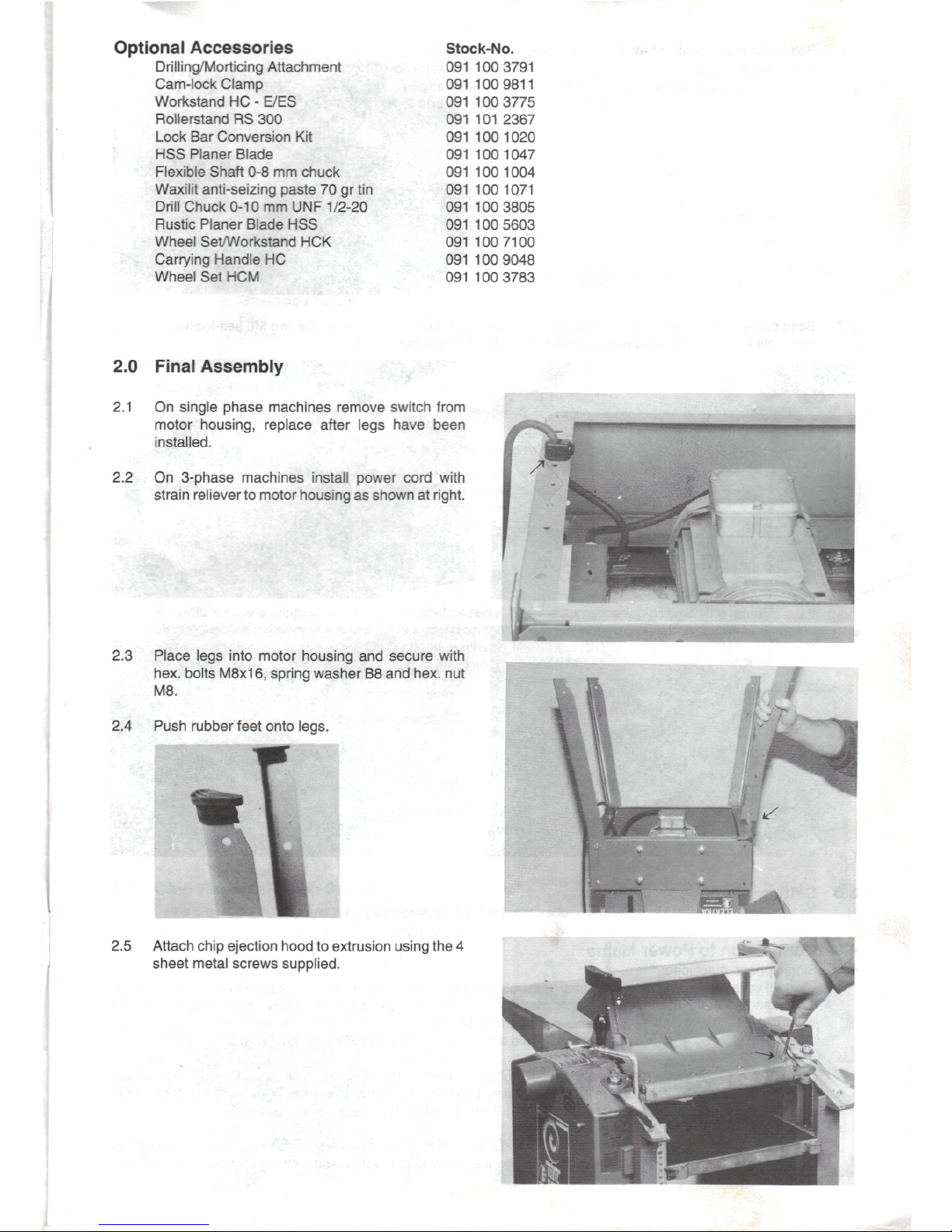
2.0
Final Assembly
2.1 On
single phase machines remove switch from
motor housing, replace after legs have been
installed.
2.2 On
3-phase machines install power cord with
strain reliever
to
motor housing
as
shown
at
right.
2.3
Place legs into motor
housing
and
secure with
hex.
bolts
M8x16,
spring washer
B8 and
hex.
nut
M8.
2.4
Push rubber feet onto legs.
2.5
Attach chip ejection hood
to
extrusion using
the 4
sheet metal screws
supplied.
Page 4

2.6
Bolt
fence carrier with 2 hex. bolts
M8 to the
infeed
table.
Pull, then
lever
swings freely
2.7
Slide carriage bolts into
the
fence extrusion
and
bolt
to
fence
segment,
using
the two M6
self-locking nuts.
Fix
cover plate
to
fence bracket with
two
cyl.
bolts M4x8
and
washers
A4.2.
3.0
4.0
4.1
4.2
4.3
Setting
of
Fence
By
turning fence setting screws
in or out as
required, adjust fence segment stops
to
true
90° and
45
C
Connection
to
Power
Mains
Single phase machines:
Check
if
voltage
of
power mains matches with voltage stated
on the
machine's type plate.
Fit
plug matching your
local standard outlet
to
power cord.
This
machine must
be
safety earthed.
The
yellow/green lead
is the
earth
conductor. A 220/240 V circuit must have a 13
amp
fuse, fitted
on a
110 V circuit a min.
20 amp
time-lag circuit
breaker
is
required. Extension cords must have a min. cross section
of 2.5
mm2/12
AWG.
3-phase
machines:
Check
if
voltage
of
power mains matches with voltage
stated
on the
machine's type plate.
Fit
plug
of
your local
standard
to
power cord. This machine must
be
safety earthed.
The
yellow/green lead
is the
earth conductor. Min.
lead cross section required
is
1.5
mm2/16
AWG. Protect circuit with
16 amp
time-lag fuses.
Direction
of
rotation
on
3-phase machines:
Switch
machine
on
briefly
to
check
cutterblock
direction
of
rotation.
If
necessary correct
by
interchanging
two
phase leads (black
or
brown).
Do not
interchange
the
yellow/green earth lead with
the
blue neutral
lead.
If in
doubt leave
job to a
qualified electrician.
Page 5

5.0
Switch
All
switches
are
equipped with a no-volt release solenoid (magnetic switch). This feature prevents
the
machine
from
starting
up
after a power
failure. A light humming from
the
switch when machine
is
switched off,
but
connected
to
power mains,
is
normal
and
does
not
represent a fault.
5.1
-IMPORTANT - WIRING
INSTRUCTIONS
Warning:
This
appliance
must
be
earthed!
For
machines with a single phase motor (220-240 volt
or
110
volt)
the
mains lead
is to be
connected
in
accordance
with
the
following
colour
code.
Green
and
Yellow - Earth
^
Blue
-
Neutral
Brown
-
Live
3-Phase
Motors
Machines
fitted
with
3-phase
motors
are
connected
to the
mains using a 5-pin
industrial
appliance-inlet/connector
to
BS
4343
(IEC 309)
Ensure
it is
wired
and
connected only
by a
qualified electrician.
c
IF IN
DOUBT - CONSULT A QUALIFIED
ELECTRICIAN!
6.0
Motor
Protection
All
switches
are
equipped with a motor protection relay, which automatically trips when
the
motor
is
overloaded.
On
single-phase machine a small
pin is
located
on the
switch housing, which simply needs
to be
pushed
in to
reset
the
motor protection relay.
On
3-phase machines
the
switch needs
to be
switched off.
After
the
motor protection relay
has
tripped
let
motor cool down
for at
least
10
minutes.
7.0
Chip
Removal
Standard delivery with this machine
is a
suction connector
of
100
mm/4" diameter.
We
recommend
to use the
Elektra Beckum Dust
Collector
SPA
1000, which
has
been
designed
specifically
for use
with
this
planer/
thicknesser.
8.0
Chip
Removal
when
Planing
Set
thicknessing
bed to
approx.
2/3
capacity
and
place suction connector onto
it.
Raise thicknessing
bed to
lock
suction connector
in
position. Make sure that
the
notch
on top of the
connector locks
on the
spacer shaft.
Page 6

9.0
Chip Removal when Thicknessing:
9.1
Thicknessing without dust collector:
Take
off
outfeed table, slide guard extrusion clear
of
table
and set
guard
to
highest position. Swing
chip ejection hood over
the
cutterblock
and
secure
in
place with
the
lock levers
as
well
as
lowering
the
guard onto
it.
I
9.2
Thicknessing with dust collector:
Bring chip ejection hood into position
as in
9.1,
then place
the
suction connector onto
it.
Secure
with
lock levers
and
guard.
Caution!
The
chip ejection hood
is the
cutterblock guard
when
the
machine
is set up for
thicknessing.
Never operate machine without chip ejection
hood
in
place
and
properly secured.
10.0 Setting
of
VARIO
Guard (Standard
on
HC-M/K/ES,
optional
on
HC-E models)
Height adjustment
is
made with
the
lever mounted
on the
left side
of the
machine.
After
lifting
the
lock lever
the
blade
cover
can be
slid sideways
to set the
required stock width
for
jointing. Push lock lever down
to
lock guard
extrusion
in
position.
.
Page 7

11.0
Planing
Place stock flush onto infeed table, with your
left
hand
set the
cutter guard
to the
required
hight
(stock should just
run
clear
of the
guard. Start machine
and
push stock slowly
and
steady against
the
cutterblock.
Hands slide over
the
blade cover.
11.1
Jointing
For
planing
the
narrow sides
of a
workpiece release
the
blade cover's lock lever
and set
blade cover
to
width
of
stock.
The
plastic spring
on the end of the
blade
cover should
exert a slight pressure against
the
stock. Lock blade
cover
in
place
and
start machine. Push stock slowly
and
steady
against
the
cutter block.
Be
sure that fence
is set at
true
90° (or ony
other angle required)
and
stock
is
kept flush against fence.
.
12.0
Thicknessing
Prepare machine
for
thicknessing
as
described
under para. 9.0.
Set
thicknessing
bed to
required
thickness
of
stock (but max.
5 mm
more than
actual thickness
of
stock). Start machine
and
place stock with planed side facing down onto
thicknessing
bed and
slowly
push
forward
until
feed
roller engages. With wedge-shaped stock
feed
thicker side
first.
Wet
stock
can be
slightly
coated with kerosene
to
improve sliding
capabilities.
For
working long stock
use of the
Elektra Beckum
roller
stand
(stock-no.
091 101
2367)
is re-
commended.
Page 8

13.0 Replacing/Setting
of
Disposable
Blades
Disconnect machine from power before
servicing!
Remove
fence.
Loosen hex.
bolts
of
lock
bar
with
tool set's spanner
SW
10
mm by
turning
the
bolts
clockwise
(into
the
lock bar). Remove lockbar
complete with blade from cutterblock. Clean lock
bar, lock
bar
seat
and
blade from chips
and
dust
with oily rag. Reverse blade
or fit
fresh
one
onto
lock bar. Place assembly into cutterblock
and
secure
in
place
by
turning hex. bolts-counter-
clockwise,
at
this stage only tighten bolts lightly.
Check projection
of
blade against outfeed table
with dial indicator
or
straight edge placed onto
outfeed
table. Max. blade projection over
outfeed table
0.1
mm/0.004 inch.
Use the
tool set's Allen
key SW 3 mm to
correct projection
by
turning
the
three setting screws
of the
lock
bar in
or
out,
as
required. When correct setting
is
reached
fully
tighten
the
hex. bolts. Start with
the
centre bolts, then
the
outer
ones.
Caution!
Do
not use
spanner
SW 10
with longer handle than supplied with machine
to
prevent excessive torque
and
possible stripping
of
threads.
For
your
own
safety replace lock bars
or
bolts with damaged thread
at
once.
Use
only genuine Elektra Beckum replacements.
i--~
Allen
key SW 3 mm
Dial indicator
14.0
Fitting/Setting
of
Resharpenable Blades
For
certain
markets
this machine
may
be
fitted with resharpenable
HSS
planer
blades
as
standard.
If
this machine
is
fitted with disposable planer blades
it can
easily
be
modified
to
accept
HSS or TCT
resharpenable blades.
14.1
To
fit
resharpenable blades, either
HSS or
TCT, a Lock
Bar
Conversion
Kit
(stock-no.
091
100
1020)
is
needed
in
addition
to the
blades. Remove standard disposable blades
as
descriped under para
13.0.
14.2
Place resharpennable blade onto lock
bar of
lock lock
bar
conversion
kit and
place assembly into cutterblock.
Tighten
hex.
bolts
lightly.
14.3
Check projection
of
blade against outfeed table with dial indicator
or
straight edge placed onto outfeed table. Max.
blade projection over outfeed table
0.1
mm/0.004 inch.
Use
Allen
key SW 3 mm to set
setting screws
of
lock bar.
14.4
When correct setting
is
achieved
fully
tighten
the
hex. bolts Start with centre bolts, then outer ones.
Caution!
Do not use
spanner
with
longer
handle
than
that
supplied
with
the
machine.
14.5
Replace lock
bar or
bolts
with
stripped thread
at
once
for
your
own
safety.
Use
only genuine Elektra Beckum
replacements.
Page 9

15.0 Belt Tension
After
the
first
5 hrs of
operation check belt tension.
Take
off cap nut
holding
the
drive belt cover
(215).
Check
tension
by
pushing against belt, play should
be
approx.
15-20
mm/5/8-2/4 inch).
16.0 Care
and
Maintenance
Regularly
clean
the
thicknesser drive gear from
dust with brush
or
compressed air. Lubricate
all
bearing
points
and
chains
regularly with
a few
drops
of
motor oil. Keep
flat
belt
free
of oil and
grease.
16.1 Regularly clean
the
thicknessing
bed
spindles
from
chips
and
dust
and
lubricate with spray
oil
(e.g.
WD 40) Do not use
regular
oil.
16.2
Keep infeed/outfeed tables
and
thicknessing
bed
free
of
resin. Clean regularly with kerosene
or
petrol, then coat
with a light
film
of
WAXILIT
antiseizing paste
to
enhance gliding
of
stock
on
tables.
17.0 Safety Instructions
-
Regularly check that blades
and
lock bars
are
locked tight
in
cutterblock
-
Max. allowable blade projection over cutterblock
1.0
mm/0.004 inch
+ 10
%.
-
Never remove
any of the
machine's safety guards other than
for
servicing
and
repair work. Keep guards
operational
at all
times.
-
Set and
secure safety guards
in
position before operating machine.
-
When operating machine
in
enclosed spaces connect
to a
dust collector.
-
This
machine
must
be
safety earthed.
The
yellow/green
lead
is the
earth
conductor.
-
Regularly check anti-kickback fingers
for
proper operation.
-
Always wear
eye
protection.
-
Rebating,
tenoning, moulding
and
recessing
may not be
undertaken
without
the use of
special
guards.
-
Never make jointing
or
planing
cut
deeper than 3 mm/1/2".
Page 10

18.0
User
Responsibility
This machine will perform
in
conformity with
the
description contained
in
this manual when
installed,
operated,
maintained
and
repaired
in
accordance with
the
instructions provided.
This machine must
be
checked periodically. Defective equipment (including power cable) should
not be
used.
Parts
that
are
broken, missing, plainly worn, distorted
or
contaminated, should
be
replaced immediately. Should
such repair
or
replacement become necessary,
it is
recommended that such repairs
be
carried
out by
qualified
persons
approved
by
Elektra Beckum
or its
representatives.
This machine
or any of its
parts should
not be
altered
or
changed from standard specifications.
The
user
of
this
machine shall have
the
sole responsibility
for any
malfunction which results from improper
use or
unauthorized
modification from standard
specification,
faulty maintenance, damage
or
improper repair
by
anyone other than
qualified
persons
approved
by
Elektra
Beckum
or its
representatives.
19.0 Wiring
Diagrams
19.1
Wiring diagram
for
motor 220-240 V 50/60
Hz
with
switch-plug-combinations
and NVR
220-240
V
19.2
Circuit diagram
for
motor
380/415 V 50/60
Hz and
220 V
50/60
Hz
switch-plug-combination
with
motor protection relay
and NVR
(solenoid
400/
230V)
3-400V
3-220V
50/60
Hz
Li
-
L2-
L3-
N
-
PE-
Page 11

20.0
Spare
Part List
HC 260
Pos.
Description
Dimension
DIN
Stock-no.
100
100
101
102
103
104
105
106
107
108
109
110
111
112
114
116
117
118
119
120
121
122
123
125
126
127
128
129
130
131
132
133
134
135
136
137
138
139
140
141
142
143
144
145
146
147
148
149
150
151
152
153
154
Planing
bed
w
Planing bed, hardened
Lock
bar
screw
Lockbar
for
disposable blades
Lockbar
for
resharpenable blades
Clamping
sleeve
for
lock
bar
Set
screw disposable blade
Set
screw resharpenable blade
Disposable planer blade
Resharpenable
planer blade
HSS
Cutter block HCM/K
Side panel
no. 3
Blind
rivet
Square
washer
Hexagon
nut
Hex.
socket head
cap
screw
Switch
HCM
Switch
HCK
Switch
HCK -
B/NL
Switch
HCM
- AUS
Switch
HCK
Switch
HCM -
GB/NZ/DK/CH
Switch
HCM - CDN
Clamping sleeve
Star
knob
Disk spring
Set
collar
Threaded
rod
Hex
socket head
cap
screw
Spacer
strip
Hex. socket head
cap
screw
Hex.
socket head
cap
screw
Cover
rail
Disk spring
Slotted cheese head screw
PVC
crank handle
Hexagon
nut
Thicknesser
bed
adjusting spindle
Thicknesser
bed
spindle
Grooved dowel
pin
Hexagon head screw
Glide
piece
HC
Washer
Feed roller, smooth
Spacer shaft w/tapped hole
Feed roller, coarse
Shim ring
Set
screw
Check
nut
Thicknesser
bed
w/pointer
Spread insert
Shim with hole
8.1
Pressure spring
Washer
Hexagon head screw
Slotted
set
screw
Pan
head tapping screw
Thicknesser
bed
scale
Shim ring
Spindle
bush
Shim
with hole 12.1
Chain
sprocket
Z=1 5 T=6
286.6x525
286.6x525
M6x11
5x10
M6x8
M6
18.6x1x260
260x20x3
RD
62.5x439
5x1
6F
M8
M6x25
2.8 DN 5 A
4.2
DN-M7A
4.2 DN
3-ph
220 V
2.2 WN 11 A
3.1 WN 15 A
1
.8/2.2
WN
2.2 WN
4x16
23.0x10.2x0.9
011
M10
060x470
M6x16
4x20x193
M6x12
M8x16
4x25x179
16.0x8.2x0.6
M6x60
M6
TR
14x3x365
TR
14x3x229.5
3x16
M6x80
A13
14x20x1.0
M5.5
TR14x3
M8x13
22x22
A
8.4
M8x80
M8x16
St
4.8x9.5
0.6x16x170
8x14x1.0
RD
16x10
22x22
32.4x15
1481
916
934
912
1481
2093
705
6912
6912
912
2093
84
934
1473
933
125
988
913
2076
125
931
7981
988
1390206760
139011
9468
148521
0365
1492020300
1492020326
650
302
9250
6164029245
6143043477
091 100
1012
091
100
1039
138521
2913
1390080260
662101
0415
1492020296
620
000
2235
612
1000766
101
1000904
101
101
1680
101
1136873
8133144243
8133144235
101 101
1426
101 101
8536
6503001681
700 706
9620
705301
0100
641
0147244
1395206555
6127059193
149201
9700
612715
1537
612 115
1101
149201
9697
705
301
6795
612001
7193
700 401
7433
6200002219
149201
9302
139501
6578
6501007275
6103008717
1391006039
630
001
6705
149501
9256
149501
9280
149501
9248
630 600
9832
616 115
1139
139501
6616
1390067107
633
001
7420
1390008895
7051005770
630 001
6322
6102001093
6160000358
617201
6683
1141073024
630 601
7266
1391029268
1390008887
724
601
7276
Page 12

Pos.
Description
Dimensions
DIN
Stock-no.
155
156
157
158
159
160
161
162
163
164
165
166
167
168
169
170
171
172
173
174
175
176
177
178
200
201
202
203
204
205
206
207
208
209
210
211
212
213
214
215
216
217
218
219
220
221
222
223
224
225
226
227
228
229
230
231
232
233
234
235
236
237
238
239
Roller
chain
pitch 8 210
links
Drive chain protection
plate
Washer
Setting bracket,
le
+ ri
Guide
rail,
left
Grub screw
Guide
rail,
right
Chip ejection hood extrusion
Pan
head tapping screw
Recoil lock segment
Recoil lock
bar
Recoil
lock
bar
Hexagon head screw
Chip
guide
plate
Spacer shaft
Chain
tension sprocket
Z-15
T=6
Nyloc
hexagon
nut
Threaded bolt
Chain
tension
plate
Chip ejection hood
Hex. socket
head
cap
screw
Pan
head tapping
screw
Hex.
socket head
cap
screw
Chip ejector hood
Fence extrusion
end
cap, right
Fence
segment
Glide segment
Hexagon
head screw
Fence extrusion
Carriage bolt
Fence extrusion
end
cap,
left
Guard extrusion
Guard
extrusion
clamping
lever
Cap nut
Guard support
Guard extrusion
end cap
Countersunk head tapping screw
Side
panel
lid
Countersunk head tapping screw
Drive
belt
cover
HCM/K
Washer
Ratched lever
Plastic washer
Fence carrier
HC
Guide
segment
Nyloc
hexagon head screw
Washer
Raised cheese head screw
Fence cover plate
PVC
pressure spring
Guard setting lever
Hex.
socket
head
cap
screw
Pressure plate
Setting
rod, cogged,
hexagonal
Gear
cover
Raised countersunk
head
screw
Shim ring
Lock lever, right
Lock
lever,
left
J-belt
pulley 5Jx42
Bearing
cup
O-ring
Grooved
ball
bearing 6203
LLU
Guide
bar
2x259x415
A
6.4
2x53x43
4x20x193
M6x8
258
St
4.8x1
3
RD
6x286
RD
10.72x286
M8x80
2x48x313
20x295
RD
32.4x9.5
M6
M6
8h9 1 3x20
2.5x25x76
M8x25
4.8x16
M8x25
ABS
M8x50
600
M6x20
M8
St
3.5x1
3
2x30x153
St
4.2x1
3
B8,4
M8
0
20x08x6
M6x10
A
4.3
4x8
1.5x190x190
M10x16
SW
14x285
M6x20
10x16x1.0
42x1
7
M
14x1
0
40x2.5
42x1
7
M1
4x1
010x75
125
916
933
985
668
7981
912
931
603
1587
7982
7982
9021
933
125
Ahl.
7985
6912
966
1093
723601
1873
139201
7620
630 001
6365
139201
7573
149201
9794
6164029245
149201
9719
1393086226
617201
5687
239
007
3596
139501
7396
139501
7388
6103030259
139201
7506
149501
9272
724
601
7365
620 200
2291
139501
7418
1392028591
139
1085141
612
1000820
617200
1830
612
1000820
139
1085133
139
1028644
1390028497
1391030606
6102008306
1393006850
611
0000608
1391028636
1393067280
1391067240
6201002131
1390067239
1391067666
6174001900
1392086508
617400
1942
1392065900
630
500
2486
700 602
8653
139
1040946
139001
5980
1390028500
6103041013
630
001
6330
6143025088
139201
7603
139
1082861
1391067259
6127151120
1492020245
149501
9264
1391067267
6134070321
6306002170
149201
9425
149201
9433
724
021
2921
1390028470
763 202
8622
710001
7703
139501
7884
Page 13

Pos.
Description
Dimension
DIN
Stock-no.
240
241
242
243
244
245
246
247
248
249
250
251
252
253
254
255
256
257
258
259
260
261
262
300
301
302
303
304
305
306
307
308
309
310
311
312
313
314
315
316
317
318
319
320
321
322
323
324
325
326
327
328
329
330
331
332
333
Fence
carrier support bracket
Hexagon
head screw
Carriage
bolt
Drive
chain
sprocket Z=25
T=38
Clamping sleeve
Bolt,
chain tensioner
Torsion spring
Chain tensioner
Roller chain pitch
6 74
links
Chain sprocket
Z=10
T=8
Threaded bolt
Bolt, short
Bolt,
long
Star
lock
w/o cap
Circlip
Shim ring
Flat belt
Flat belt pulley
Cam
wheel Z=25
T=38
Disk
spring
Hexagon
nut
Drill chuck cover
Thicknesser
drive gear cover
Spacer bush
Washer
Carrying handle
Hexagon head bolt
Side
panel, neutral
Hexagon
head bolt
Spring washer
Blind
rivet
Front
panel, CONDOR switch
Poly-V-belt
Hexagon
head screw
J-belt
pulley,
50 Hz
J-belt
pulley,
60 Hz
Feather
key
Hex.
socket head
cap
screw
Motor carrier
HCM/K
Carriage bolt
Capacitor
Capacitor
Capacitor clamp
Pan
head
tapping
screw
Motor
HCM
Motor
HCK
Motor
HCK
Motor
HCM
Motor
HCM
Motor
HCK
Rear
panel
Axle
bracket, right
Hexagon head screw
Washer
Spring washer
Axle
Hexagonal thin
nut
Wheel
Star
lock with
cap
Axle
bracket, left
Steel tube,
handle
Handle
PVC
LegHC
Rubber
foot
75
shore
M6x20
933
M8x40
603
69x16
4x20
1481
016x60.5
4x20x90
30.5x6.5
014x20
0
20x64.5
0
20x89
08
16x1.0
471
16x22x1.0
988
168x3.2x1.8
69x16
34.0x12.3x1.0 2093
1/2"
06/0
15x18
B 6.4
9021
M8x16
933
M
6x40
933
A
8.4
6798
6x8
F
5
PJ 864
7867
M
12x1.5Li.x25
961
5Jx94
A
6x4x30 6885
M6x16
912
M8x16
603
37.5^F/400
V
30.0^F/400
V
045
3.9x9.5 7981
2.8kW
380/41
5V
4.2
kW
380/41
5V
4.2 kW 230 V
3-ph
1
.8
kW/220-240
V
2.2 kW
220-240V
3.1 kW
220-240
V
6x16
958/933
B 6.4
9021
A
6.4
6798
0
20x526
M
16
936/439
100/35.5
012
2390008913
6103001135
611
001
5990
724 601
7284
650300
1665
139501
6586
705
1005753
1492020237
723601
1865
724
601
7292
1395028584
139501
6608
139501
6594
701
6056183
640 000
9900
630
600
9760
091
1008556
724
201
7301
724 701
7342
705 301
0096
620 901
7227
1391007027
1391005997
644
202
5779
630 500
2087
101 121
0127
6103001178
1392065829
610300
1151
630400
1745
662
1009530
1392067007
091
1007240
610300
1267
724 006
6690
724
020
7677
672
1059322
612
1023081
1392065837
611
0000632
805001
1829
805001
1810
1332025186
6172001791
801
304
6892
801 308
7769
801
302
6638
801 201
9603
801
202
7460
801
208
7757
1392065799
1392077215
610301
5675
630 500
2087
630
408
4047
149501
9345
620 503
2396
727 002
8750
701 602
5628
1392077207
201
1000625
700 802
2431
1392026530
705
701
9365
Page 14

If!
LQ
Page 15

Page 16

ELEKTRA
BECKUM
Aktiengesellschaft
Postfach
13 52,
D-49703
Meppen
cc
EG-Konformitatserklarung
- EC
conformity
declaration - Declaration
de
conformite
GEE
EG-verklaring
van
overeenstemming - EF-overensstemmelsesattest - EG-konformitetsdeklaration
EF-konformitetserklasring - Selvitys
ey-standardinmukaisuudesta - Dichiarazione
di
conformita
CE
Declaracion
de
conformidad-UE - Declaragao
de
conformidade
CE
Wir
erklaren,
daB
die
Bauart
der
Maschine/des
Cerates
- We
declare that
the
design
of the
machine/appliance
Nous
certifions
que
le
type
de la
machine/de
I'appareil - Wij
verklaren
dat de
constructie
van de
machine/het
apparaat
Vi
erklaerer,
at
konstruktionen
af
maskinen/apparatet - Harmed
forsakrar
vi
aft
maskin/apparat
- Vi
erklaerer
at
konstruksjonsmaten
til
maskin/apparat
Taten
selvitamme,
etta
alia
mainittu
kone/laite - Dichiariamo
che
il
modello
della
macchina/dell'apparecchio
Declaramos,
que el
modelo
de la
maquina/aparato - Declaramos
que o
tipo
de
construgao
da
maquina/do
aparelho
Abricht-
und
Dickenhobelmaschine
HC
260
M/2200
WNB - HC 260
K/3100
WNB - HC 260
M/2800
DNB - HC 260
K/4200
DNB
Art.-Nr. - Stock-no. - N°
d'
article - art.-nr. - art.-nr. - Art.-nr. - Art.-Nr. - tuotenumero - N°
Art. - Art.N* - artigo
n°:
011
3026081
- 011
2026053
- 011
3026090
- 011
2026061
folgenden
einschlagigen
Bestimmungen entspricht - corresponds with
the
following relevant regulations
est
conforme
aux
reglements
applicables suivants
- aan de
volgende
terzake
geldende
voorschriften
voldoet - opfylder
falgende
gaeldende
bestemmelser
enligt
sin
byggsatt
motsvarar
foljande
gal/ande
foreskrifter - oppfyller
de
folgende
gjeldende bestemmelser
vastaa
seuraavia asiaa koskevia
maarayksia - corrisponde
alle
seguenti
norme
in
materia
se
a/usta
a las
siguientes
directrices correspondientes
- se
enquadra
com as
seguintes
disposicoes
pertinentes:
EG-Maschinenrichtlinie
- EC
machine directive - directive
GEE
pour
les
machines - EG-machinerichtliln
- EF
maskindirektiv - EG-maskindirektiv
EF
maskindirektiv - Koneita
koskeva EY-direktiivi - Direttiva
CE per
macchinari - Directriz
de
maquinas-UE - Directiva
CE
para
maquinas
89/392/EWG
EG-Richtlinie
Elektromagnetische
Vertraglichkeit - EC-directive electro-magnetic compatibility - directive
GEE
sur la
conformite
electromagnetique
EG-richtlijn
elektromagnetische
compatibiliteit - EF-direktiv vedr. elektromagmetisk fordragelighed - EG-direktiv
for
elektromagnetisk
tolerans
EF-direktiv
om
elektromagnetisk kompatibilitet - Sahkomagneettista
toleranssitasoa koskeva EY-direktiivi - Direttiva
CE
compatibility
elettromagnetica
Directriz-UE
Compatibilidad electromagnetica - Directiva
CE
sobre compatibilidade electromagnetica
89/336/EWG
Angewendete
harmonisierte
Normen - Applied harmonized standards - normes
harmonisees
appliquees - Toegepaste
geharmoniseerde
normen
Anvendte harmoniserede standarder - Tillampade
harmoniserande
direktiv - Anvendte tilpassede normer - Sovelletut
harmonisoidut
normit
Norme
armonizzate
applicate - Normas
armonizantes
aplicadas - Normas
harmonizadas
aplicadas:
DIN-EN 294;
EN
60204-1
Angewendete
nationale
Normen - Applied national standards - normes
Rationales
apppliquees - Toegepaste
nationals
normen
Anvendte
tyske
standarder - Tillampade nationella direktiv - Anvendte nasjonale normer - Sovelletut kansalliset normit - Norme
nazionali
applicate
Normas
nacionales
aplicadas - Normas
nacionais
aplicadas
VBG
7j; ZH
1/3.8;
DIN
45635
Teil
1650
Die
Baumusterprufung
wurde
von
folgender gemeldeter Stelle
durchgefuhrt
- The
type
test
was
carried
out by the
following registered location
L'homologation a ete
effectuee
par
I'office suivant
- De
constructiemodel-keuring
werd
door
de
volgende
officiele
instantie uitgevoerd
Typem0nsterpr0ven
er
gennemfart
af
folgende
registrerede institut - Monsterprovet
utfordes
pa
fo/jande
auktoriserad
institution
Prototypen
ble
testet
av
felgende
registrerte
institusjon - Mallikappaleen
tarkastuksen
on
suorittanut
seuraava
rekisteroity
laitos
L'omologazione e stata
effettuata
dal
seguente
ufficio
- El
ensayo
de la
muestra constructiva
ha
sido realizada
por la
siguiente institution autorizada
A
inspeccao
do
modelo
de
construcao
foi
realizada
pela
seguinte autoridade:
TUV-Rheinland,
Postfach
910351,
D-51101
Koln
Nummer
der
EG-Baumusterprufbescheinigung - Number
of the EC
type
test certificate - Nummero
d'homogolation
GEE
Nummer
van
het
EG-constructiemodel-certificaat - EF-typem0nsterpr0veattestens
nummer - EG-provintygets
nummer
Nummeret
pa
EF-prototyptestsertifikatet - EY-mallikappaletarkastustodistuksen
numero - Numero
del
certificate
di
omologazione
CE
Numero
de la
Certificacion-UE
de la
muestra constructiva - Numero
do
certificado
de
inspeccao
CE
para o modelo:
9311212
Technischer
Leiter - Technical
Manager
- Le
responsable
technique - Cheftechniek - Teknisk
leder - Produktledare
Teknisk
leder - Tekninen
johtaja - Direttore
tecnico - Director
tecnico
- 0
director
tecnico
1000615
D/GB/F/NL/DK/S/N/SF/I/E/P
 Loading...