

Page 1
G
Operating Instruction
Planer
DH 315
UP
WN
DO
Page 2

Please return the enclosed warranty card to us.
Retain proof of purchase! You are only entitled to claim warranty against
G
Great Britain
proof of purchase.
Please see back cover for manufacturer representative´s address nearest you.
Redaktion: Zindel • Technische Dokumentation und Multimedia • D-22417 Hamburg
Page 3
1
2
3
4
5
6
7
8
9
10
11
12
13
14
15
16
17
18
19
20
21
22
XW0001E.fm
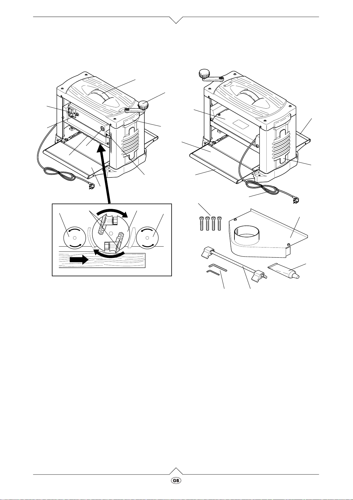
Getting to know your planer
1Great Britain
8
7
14 171615
1
2
UP
WN
DO
1
5
6
3
4
9
13
10
18
DO
WN
UP
10
11
12
19
Carrying handles
Crank for thicknesser bed rise and fall
Workpiece thickness indicator
Planer bed
Screw plug for carbon brushes
Anti-kickback lock
Reset button
On/off switch
Cutterblock cover
Feed rollers
Cable holder
22
21
Components inside the planer/thicknesser:
Infeed roller
Cutter knife
Cutterblock
Outfeed roller
Standard accessories supplied:
Mounting bolts for fixing the machine base
Dust extraction adaptor
Sliding wax for table surfaces
Knife setting gauge
20
DH 315
Power supply cable
Outfeed table
Allen keys 4 mm and 6 mm
1
Page 4

Read first
·
Read these instructions before use Pay special
attention to the safety information.
·
If you notice transport damage while
unpacking, notify your supplier immediately. Do
not operate the machine.
·
Dispose of the packing in an environmentally
friendly manner. Take to a proper collecting
point.
·
Keep these instructions for reference on any
issues you may be uncertain about.
·
If you lend or sell this machine be sure to have
the instructions go with it.
Safety information
Specified conditions of use
This machine is intended for thickness planing of
solid timber. The permissible workpiece dimensions must be observed (see technical specifications).
Any other use is not as specified. Any use not as
specified, modifications to the machine, or use of
parts not tested and approved by the equipment
manufacturer can cause unforeseen damage!
General safety information
Observe the basic safety rules for the operation of
electric tools, to keep the risk of
-
personal injury
-
fire
-
electric shock
as little as possible.
Please note in particular:
A planer is a dangerous tool which can, due to operator carelessness, cause serious personal injury. It
is therefore recommended you follow the safety
information given below, and know and follow the
legal regulations pertaining to the operation of planers.
Danger!
A
The planer shall only be started and operated by persons being familiar with the operation of planers, and at any time are aware of
the hazards associated with the operation of
such machines.
Persons under the age of 18 shall operate
this machine only in the course of their vocational training under the supervision of an
instructor.
The following residual risks principally exist
with planers and can not, even by employing
safety devices, completely eliminated:
-
Entanglement hazard: In the course of
planing, the workpiece is automatically
drawn in and fed through the machine.
You must therefore ensure that no parts of
the body or objects can be drawn into the
planer together with the workpiece, while
the planer is in operation. Do not wear
apparel that can get caught and drawn in
by the machine: ( no ties, no clothes with
wide sleeves).
-
Risk of workpiece kickback (workpiece is
caught by the cutterblock and hurled
against the operator):
Operate machine only with a fully functional anti-kickback lock. Always use sharp
cutter knives. If in doubt, inspect workpiece for the presence of foreign matter
such as nails or screws.
-
Hazard generated by insecure planer
stand: When working long stock use suitable workpiece supports on both sides of
the planer.
Prevent adverse body positions. Ensure
firm footing, and keep your balance at all
times.
-
Use planer within its limits, and only as
specified. Prevent adverse body positions.
-
Risk of injury by touching the revolving
cutterblock: Always keep sufficient
distance to the cutterblock. Switch the planer off when not in use.
-
Risk of cut with the cutterblock at standstill: Wear gloves when changing cutter
knives.
-
Hazard generated by environmental conditions:
Do not operate the planer in rain or wet
surroundings. Ensure sufficient lighting.
Do not operate the planer near inflammable liquids or gases.
-
Hazard by overloading the planer:
Use the planer only within its stated capacity range. Use the planer only as specified.
-
Hazard generated by defects of the planer:
Check planer for defects before each use
Before starting the planer make sure that
no objects (e.g. tools) are inside the
machine. Do not use the planer with a
damaged ON/OFF switch.
2
DH 315
Page 5
Safety devices
Anti-kickback lock (A)
The anti-kickback lock prevents a workpiece being
thrown back against the operator by the rotating
cutterblock.
The anti-kickback lock must not be bent.
UP
WN
DO
A
Cutterblock cover (B)
The cutterblock cover prevents that the upper part
of the cutterblock can be touched from the top.
While the machine is not unplugged and the cutterblock has not stopped, the cutterblock cover must
be installed.
Instead of the cutterblock cover a dust extraction
adaptor can be installed.
Operating controls
On/off switch
·
To switch ON = press green switch button.
To switch OFF = press red switch button.
An undervoltage relay trips in the event of a
3
voltage failure, to prevent a restarting of the
machine when the power is restored. To
restart the machine the green button must be
actuated again.
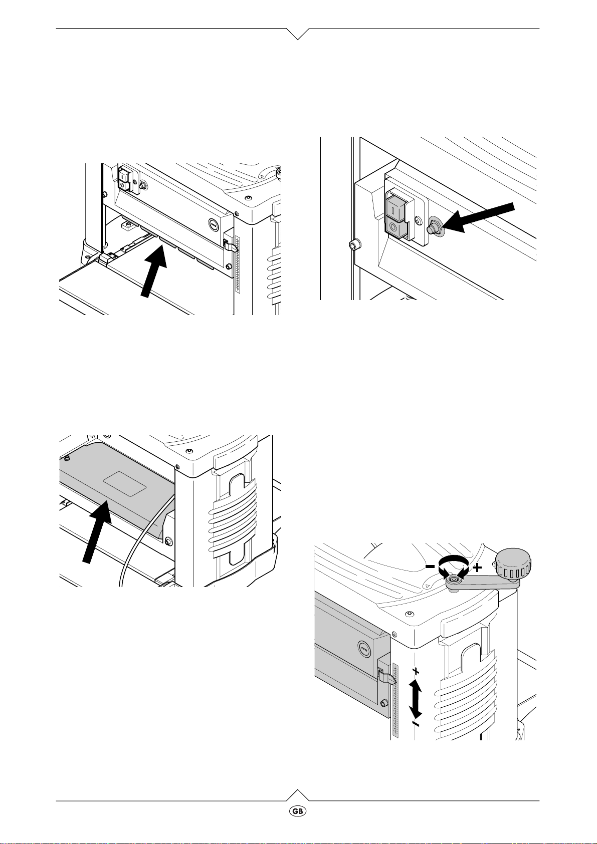
Reset button for overload relay
The planer/thicknesser has a build-in overload protection (arrow). This stops the machine if the motor
becomes too hot. To restart the planer/thicknesser:
1. If necessary, let motor cool down;
2. depress the reset button;
3. press green switch button.
B
Rise and fall mechanism
With the rise and fall mechanism the planing thickness (= workpiece thickness after thicknessing) is
set. Workpieces of up to max. 153 mm thickness
can be worked.
UP
WN
DO
DH 315
3
Page 6

Installation and connection
Fixing the planer
To keep the machine from „wandering” by vibrations or from tipping over, it needs to be screwed to
a workbench, workstand or similar support:
1. Drill four holes into the support.
2. Fit screws through holes from the top and
secure from below with washers and nuts.
If the planer/thicknesser is to be used
3
mobile:
-
screw the planer to a sheet of 19 mm plywood. This plywood sheet should on all
sides project approx. 100 mm over the
machine base. Make sure that the bolts do
not project from the underside of the plywood sheet.
-
At the workplace, attach the plywood
sheet with G-clamps to a workbench,
workstand or similar support.
Installation of the rise and fall mechanism crank
·
Place crank on the shaft and secure with a
screw.
If no dust collector is used there is chip buildup inside the housing, particularly at the cutter knives. These remains cause a rough
surface. Therefore the chips need to be
removed regularly.
Danger!
A
Always unplug before removing the cutterblock cover!
1. Unscrew both screws and remove the cutterblock cover from the planer.
2. Fit dust extraction adaptor instead of the cutterblock cover and secure with two screws.
UP
WN
DO
Connection of a dust collector
Danger!
A
Some kinds of wooden dust (e.g. from oak
and ash) can be carcinogenic when inhaled.
Always connect to a suitable dust collector
(air speed at the planer's dust collection port
³
20 m/s) when working indoors.
Caution! Operation without a dust collector
A
is only possible:
-
outdoors;
-
if only small amounts of chips are produced (with narrow stock and only slight chip
removal);
-
with a dust mask.
3. Connect the suction port to a suitable dust collector.
4
DH 315
Page 7

Assembling the knife setting gauge
The setting gauge is necessary to install the cutter
knives with the correct projection (1.5 mm).
1. Put a circlip to both inner spring ring grooves.
2. Slide a spacer block on each end of the shaft.
3. Fit a circlip to each of the outer spring ring
groove.
Mains connection
Danger! Electrical Hazard
B
Operate machine in dry environment only.
Operate machine only on a power source
matching the following requirements (see
also "technical specifications"):
-
fuse protection by a residual current operated device (RCD) of 30 mA sensitivity;
-
outlets properly installed, earthed and
tested;
Position power supply cable so it does not
interfere with the work and is not damaged.
Protect power supply cable from heat,
aggressive liquids and sharp edges.
Use only rubber-jacketed cable of sufficient
lead cross-section.
Do not pull on power supply cable to unplug.
·
After the machine with all safety devices has
been assembled, plug the power cable in.
Operation
·
Check the following for proper operation before
starting work:
-
On/off switch;
-
anti-kickback lock;
-
cutterblock cover;
· Use personal protection gear:
- dust respirator;
- hearing protection;
- safety glasses.
· Assume proper work position for planing:
- in front of the machine on the infeed side;
- frontal to the machine;
· Use if required for the type of work:
- Workpiece support (e.g. roller stand) – to
prevent machine from tipping by workpiece
weight;
- push stick (feeding aid) –for small workpieces that are not drawn in by the machine;
- dust extraction kit (accessory);
- sliding wax – to make workpieces run
smoothly through the machine. Apply a thin
film of sliding wax to surface of both infeed
and outfeed table.
Danger!
A
- Keep your hands away from the machine's
inside! Risk of personal injury by the rotating planer knives.
- Use a push stick (feeding aid) if you are to
feed small workpieces into the planer.
- Do not jam workpiece. Risk of kickback.
- Remove jammed stock only after the
motor is at complete standstill and the
power cable unplugged.
- Replace dull planer knives immediately.
Risk of kickback, if a dull knife gets caught
in the workpiece's surface.
Entanglement hazard
c
- Do not wear loose clothing, jewelry or
gloves, which can get caught by rotating
machine parts.
- Contain long hair with a hairnet.
DH 315
5
Page 8

Planing workpieces
The planer can remove max. 3 mm material
3
in one pass. This capacity, however, shall
only be utilized:
- with very sharp planer knives;
- with soft timber;
- if the max. planing width is not utilized.
Otherwise there is a risk of overloading the
machine.It is best to make several passes,
until the workpiece has the desired thickness.
Workpiece dimensions
length width height
min. 130 mm min. 64 mm min. 5 mm
over 1500 mm
use additional workpiece
support
1. Fold both infeed and outfeed table down.
2. Set planing thickness with the crank.
Risk of kickback!
A
Set the planing thickness only with the cutterblock at standstill!
max. 318 mm max. 153 mm
UP
WN
DO
Risk of personal injury!
A
Never reach with your hands inside the
machine while guiding a workpiece! Guide a
workpiece from the outfeed end, when it is
drawn so far into the machine that it can no
longer be safely guided from the infeed side.
6. Switch the machine off, if no further planing is
to be done immediately afterwards.
Care and maintenance
Danger!
A
Prior to all servicing:
- Switch machine OFF.
- Unplug power cable.
- Wait until the saw has come to a complete
stop.
· Check that all safety devices are operational
again after each service.
· Replace defective parts, especially of safety
devices, only with genuine replacement parts.
Parts not tested and approved by the equipment manufacturer can cause unforeseen damage.
· Repair and maintenance work other than
described in this section should only be carried
out by qualified specialists.
Alignment of infeed and outfeed table
1. Fold both infeed and outfeed table down.
2. Place a straight board, steel ruler or straight
edge across both infeed and outfeed table:
3. Start motor (press green switch button).
4. Feed workpiece slowly over the planer bed.
The workpiece is fed automatically.
5. Guide workpiece in a straight line through the
machine.
6
UP
WN
DO
- The board / straight edge must rest on both
rollers and must not sag in the middle.
- Infeed and outfeed table are correctly set if a
sheet of paper will just fit between board/
straight edge and thicknesser bed.
DH 315
Page 9

3. To align, fold infeed and outfeed table up and
set the two each backstop setting screws
(arrow) as required.
Cutter knife replacement
Dull cutter knives are noticeable by
3
- reduced performance;
- increased risk of kickback;
- stalling of the motor.
Danger!
A
Risk of cut by the cutter knives! Wear gloves
when changing cutter knives.
To remove the cutter knives:
1. Unplug power cable.
2. Fold outfeed table down.
3. Lower the cutterblock.
4. Unscrew and remove the cutterblock cover/dust
extraction adaptor respectively.
7. Remove both cutter knife and lock bar.
8. Clean surfaces of cutterblock and lock bar.
Danger!
A
Do not use cleaning agents (e.g. to remove
residue resin) that could harm the light metal
components; it could have an adverse effect
on the stability of the planer.
9. Place lock bar into cutterblock as illustrated.
5. Turn cutterblock by hand (use gloves!) until the
lock bar is on top.
6. Unscrew the cutter knife lock bar screws.
The cutter knives are being pushed up by
springs when the screws are loosened.
DH 315
1,5mm
10. Place fresh cutter knife into cutterblock as illustrated.
7
Page 10

Please note: The cutter knife has an edge
3
on both sides. If the reverse side edge is still
sharp, it suffice to reverse the cutter knife.
Danger!
A
- Use only suitable cutter knives (see „technical specifications“) – unsuitable, incorrectly installed, dull or damaged cutter
knives can work loose or greatly increase
the risk of kickback respectively.
- Always make sure that both cutter knives
are replaced or reversed.
- Install cutter knives only using genuine
parts.
11. To set the knife projection exactly, press the
knife setting gauge onto the cutterblock as illustrated, then tighten the lock bar screws:
- To prevent distortions of the lock bar, start
with the screw in the centre, then tighten the
screws closer to the edge, step by step;
- Release knife setting gauge only after all
screws have been tightened.
Danger!
A
- Do not extent tightening wrench.
- Do not tighten the screws by hitting on the
tool.
12. Remove all tools and setting gauges from the
machine!
13. Replace and fasten the cutterblock cover/dust
extraction adaptor respectively.
Carbon brush check and replacement
Worn carbon brushes are noticeable by
3
- stuttering running of the motor;
- Interference of radio and TV reception
when the motor is running;
- stalling of the motor.
To check or replace the carbon brushes:
1. Unplug power cable.
2. Unscrew the carbon brush cap on the motor
housing with a suitable screw driver.
The illustration shows the replacement of the
front carbon brush. The rear brush is located on
the opposite side.
6mm
3. Pull carbon brushes out and check. Each brush
must be at least 6 mm long.
4. Put intact carbon brushes back into the brush
holder. The two tongues on the sides of the
small metal plate must fit into the grooves of the
brush holder.
5. Screw the brush cap back on.
6. Check function of the machine.
Machine cleaning and lubrication
1. Unplug power cable.
2. Fold both infeed and outfeed table down.
3. Unscrew and remove the cutterblock cover.
4. Remove chips with a vacuum from:
- cutterblock rise and fall mechanism;
- cutterblock
- motor vent slots
5. Replace and fasten the cutterblock cover.
6. Apply a light coat of oil to the cutterblock rise
and fall mechanism (spindles).
7. Apply a light coat of wax to both infeed and outfeed table.
Machine storage
Danger!
A
Store the machine so that
- it can not be started by unauthorized persons, and that
- nobody can get hurt by the stored
machine.
8
Caution! Do not store unprotected outdoors
A
or in damp environment.
DH 315
Page 11

Machine transportation
1. Fold both infeed and outfeed table up.
2. Wind power cable around cable holder on the
machine's side.
Service plan
Prior to operation
Motor does not run
Motor overheated,
e.g. by
- dull cutter knives
- overloading
- chip build-up in the
cutterblock cover
Remove cause for
overheating, let cool
down for a few minutes, then depress the
reset button and
restart the planer.
- Inside of machine
- Threaded spindles of
rise and fall mechanism
- Dust spout (when
working without dust
collection)
Infeed and outfeed
table
Monthly (if used daily)
Threaded spindles of
rise and fall mechanism
Alignment of infeed
and outfeed table
Power supply cable Check for damage, if
Carbon brushes of
motor
Remove chips and
dust
Apply a thin coat of sliding wax.
Saw blade change
Check, adjust if necessary
necessary have replaced by a qualified electrician.
Check, replace if
necessary
Troubleshooting
Danger!
A
Before carrying out any fault service or
maintenance work always:
- Switch machine OFF.
- Unplug power cable.
- Wait until cutterblock is at standstill.
Check that all safety devices are operational again
after each service.
Motor does not run
No-voltage relay tripped by a temporary
power failure.
Switch on again.
Carbon brushes worn Replace carbon brus-
hes.
Power wanes
Cutter knives dull Replace with fresh cut-
ter knives.
Planed surface too rough
Cutter knives dull Replace with fresh cut-
ter knives.
Cutter knives blocked
by chips
Stock contains still too
much moisture
Planed surface cracked
Cutter knives dull Replace with fresh cut-
Cutter knives blocked
by chips
Workpiece was planed against the grain
Too much material
removed in one pass
Feed rate too little
Support surface for
workpiece fouled
In- and outfeed rollers
binding
Workpiece jammed
Too much material
removed in one pass
Remove chips.
Dry workpiece.
ter knives.
Remove chips.
PLane workpiece with
the grain.
Make several passes
with less chip removal.
Clean support surfaces and wax slightly.
Have feed rollers serviced.
Make several passes
with less chip removal.
No supply voltage Check cables, plug,
outlet and mains fuse.
DH 315
9
Page 12

Technical specifications
Voltage V 230 ~ 50 Hz
Min. fuse protection A 10
Motor capacity W 1500
Cutterblock no-load speed min
-1
10.000
Feed rate m/min 8.0
Workpiece thickness min.
max.
Workpiece width min.
max.
Dimensions depth (folded up)
width
height
Dimensions length (thicknesser bed)
width (thicknesser bed)
mm
mm
mm
mm
mm
mm
mm
mm
mm
3
153
64
318
350
540
410
600
370
Weight kg 31.5
Noise emission values according to DIN 45635
A-sound pressure level LpA
A-sound power level LWA
dB (A)
dB (A)
97
105
Wiring diagram
1~
230 V
50 Hz
L1
N
PE
SB
EM Core
EM Filter
UV
M
1~
FR : 9A
230 V
~ 230 V
50 Hz
1,5 kW
10
DH 315
Page 13

2
3
4
5
6
7
8
9
10
YW0001E2.fm
Spare parts list
DH 315
Item Description Stock-no.
1
Handle 138 164 9225
Chain set 138 864 9280
Cutterblock bearing block 138 864 9271
Rubber roller 138 864 9263
Lock bar with screws 138 264 9253
Pressure springs (4-pc. set) 138 864 9247
Drive belt with belt disc 138 864 9239
Crank assembly, rise and fall mechanism 138 864 9220
Cutter knives, pair 091 105 3152
Cutter knife setting gauge 138 864 9204
11
Page 14

Item Description Stock-no.
11 Table extension 101 164 9196
12 Bevel wheel set (1 pair) 138 864 9182
13 Repair set for spindle 138 8649 174
14 Spindle rise and fall, left 138 5649 165
15 Spindle rise and fall, right 138 564 9157
16 overload protection 811 664 9145
Item Description Stock-no.
17 Switch c/w switch cap 101 164 9137
18 Carbon brushes (2-pc. set) 138 864 9123
19 Motor c/w gear case 101 164 9110
12
DH 315
Page 15

Aktiengesellschaft
Postfach 13 52, D-49703 Meppen
EG-Konformitätserklärung - EC conformity declaration - Déclaration de conformité CEE
EG-verklaring van overeenstemming - EF-overensstemmelsesattest - EG-försäkran om överensstämmelse
EF-konformitetserklæring - EY-vaatimuksenmukaisuusvakuutus - Dichiarazione di conformità CE
Declaración de conformidad-UE - Declaração de conformidade CE
Wir erklären, daß die Bauart der Maschine/des Gerätes - We declare that the design of the machine/appliance
Vi erklærer, at konstruktionen af maskinen/apparatet - Härmed försäkrar vi att maskin/apparat - Vi erklærer, at maskinens/apparatets konstruksjon
Ar t .-Nr . - Stock-no . - N
Nous certifions que le type de la machine/de l’appareil - Wij verklaren dat de constructie van de machine/het apparaat
Vakuutamme, että allamainittu kone - Dichiariamo che il modello della macchina/dell’apparecchio
Declaramos, que el modelo de la máquina/aparato - Declaramos que o tipo de construção da máquina/do aparelho
Dickenhobelmaschine
DH 315
°
d’ ar ticle - art.-nr. - art.-nr. - Art.-nr. - art.-nr. - tuotenumero - N° Ar t . - Art.N° -
020 0031 504
artigo n°:
est conforme aux règlements applicables suivants - aan de volgende terzake geldende voorschriften voldoet - opfylder følgende gældende bestemmelser
EG-Maschinenrichtlinie - EC machine directive - directive CEE pour les machines - EG-machinerichtlijn - EF maskindirektiv - EG maskindirektiv
EF maskindirektiv - Koneita koskeva EY-direktiivi - Direttiva CE per macchinari - Directriz de máquinas-UE - Directiva CE para máquinas
folgenden einschlägigen Bestimmungen entspricht - corresponds with the following relevant regulations
är i överensstämmelse med följande gällande föreskrifter - oppfyller følgende gjeldende bestemmelser
vastaa seuraavia asiaa koskevia määräyksiä - corrisponde alle seguenti norme in materia
se ajusta a las siguientes directrices correspondientes - se enquadra com as seguintes disposições pertinentes:
89/392/EWG
93/68/EWG
EG-Richtlinie Elektromagnetische Verträglichkeit - EC-directive electro-magnetic compatibility - directive CEE sur la conformité électromagnétique
EG-richtlijn elektromagnetische compatibiliteit - EF-direktiv vedr. elektromagmetisk fordragelighed - EG-direktiv för elektromagnetisk kompatibilitet
EF-direktiv om elektromagnetisk kompatibilitet - EY:n sähkömagneettista yhteensopivuutta koskeva direktiivi - Direttiva CE compatibilità elettromagnetica
Directriz-UE Compatibilidad electromagnética - Directiva CE sobre compatibilidade electromagnética
89/336/EWG
EG-Niederspannungs-Richtlinie - EC-Low voltage directive - Directive CEE de basse tension
EG-laagspanningsrichtlijn - EF-lavspændingsdirektiv - EG-direktiv för lågspänning
EF-direktiv for lavspenning - Pienjännitettä koskeva EY-direktiivi - Direttiva CE per bassa tensione
Directriz para baja tensión-UE - Directiva CE sobre baixa tensão
73/23/EWG
93/68/EWG
Angewendete harmonisierte Normen - Applied harmonized standards - normes harmonisées appliquées - Toegepaste geharmoniseerde normen
Anvendte harmoniserede standarder - Tillämpade harmoniserande direktiv - Anvendte tilpassede normer - Sovelletut harmonisoidut normit
Norme armonizzate applicate - Normas armonizantes aplicadas - Normas harmonizadas aplicadas:
EN 292 -1, EN 292 - 2; EN 60204-1,
Anvendte tyske standarder - Tillämpade nationella direktiv - Anvendte nasjonale standarder - Sovelletut kansalliset normit - Norme nazionali applicate
Angewendete nationale Normen - Applied national standards - normes nationales apppliquées - Toegepaste nationale normen
Normas nacionales aplicadas - Normas nacionais aplicadas
prEn 691, prEN 860
(Rugen)
Technischer Leiter - Technical Manager - Le responsable technique - Chef techniek - Teknisk leder - Teknikansvarig
Teknisk leder - Tekninen johtaja - Direttore teccnico - Director técnico - O director técnico
D/GB/F/NL/DK/S/N/SF/I/E/P 1000865/ 98
Page 16

B
D
K
Belgium
Elektra Beckum Belgium N.V.S.A.
Industriezone
Hofte te Bollebeeklaan
B-1730 Asse-Mollem
Tel.: 0032-24540454
Fax: 0032-24540450
Deutschland
Elektra Beckum AG
Daimlerstraße 1
D-49716 Meppen
Tel.: 01803-333 456
Fax: 01803-333 457
Danmark
Elektra Beckum Danmark
Lundeborgvej 9
Postbox 8113
DK-9220 Aalborg OE
Tel.: 0045-98-151300
Fax: 0045-98-151451
G
I
N
Great Britain
Elektra Beckum Machinery Ltd.
6 The Quadrangle
Premier Way
GB-SO51 9AQ Romsey
Tel.: 0044-1794-834900
Fax: 0044-1794830083
Italia
Elektra Beckum AG Germania
Daimlerstraße 1
D-49716 Meppen
Tel.: 0049-1803-333456
Fax: 0049-1803-333457
Norge
Profilma-Import A/S
Postboks 536 Nanset
Sophus Buggesvei 48
N-3252 Larvik
Tel.: 0047-33114777
Fax: 0047-33114108
E
F
J
España
Elektra Beckum Import S.A.
Apartado de correos n˚ 192
E-43830 Torredembarra (Tarragona)
Tel.: 0034-9-77642110
Fax: 0034-9-77641770
France
J. Muller
1.Place de Lábattoir
F-67190 Mutzig
Tel.: 00333-88479971
Fax: 00333-88479970
Suomi/ Finland
Nofa OY
P.O.Box 28
Hannuksentie 1
FIN-02270 Espoo
Tel.: 00358-9804-861
Fax: 00358-9803-9485
H
P
S
Nederland
Elektra Beckum Nederland
Einsteinstraat 15
NL-1704 RT Heerhugowaard
Tel.: 0031-7257-44660
Fax: 0031-7257-44250
Portugal
Costa & Garcia S. A.
Vilar do Paraíso, Ap. 23
P-4408 Valadares
Tel.: 00351-2-7121279
Fax: 00351-2-7124670
Sverige
HDF-Paulsson AB
Box 525
Svaravaregatan 5
S-30180 Halmstad
Tel.: 0046-35-154400
Fax: 0046-35-121780
DH 315 115 164 8513 GB 0799 1.2
 Loading...