

Page 1
Operating Instruction
Compressed Air-Dryer
Cool 201
Cool 401
I14 5003 EGB
03.03
Page 2

Type Code
Serie
Version
Cool 201 405AP
Cool 401 407AP
Types equipped with electromagnetic
drainvalve according 2.6.1 and 3.8.1.
(Types equipped with sensor operated
drainvalve according 2.6.1, 3.8.2 and 5.1.6 are
not available.)
03.03
2
Page 3
T ab le of contents
Page
Type Code
Part 1 Important user infor-
mation
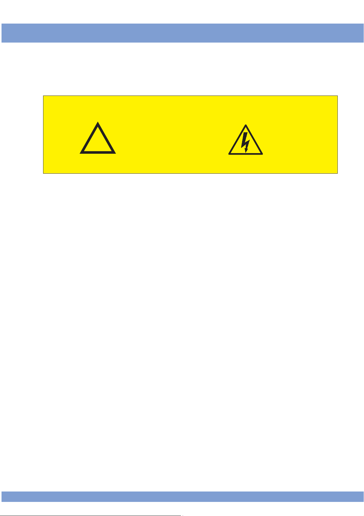
All safety notes in this operating instruction which may cause harm to personnel
or equipment, when ignored, are marked by the following symbols:
1.1 General Notes 4
1.2 Safety regulations 5
1.3 Handling with refrigerant 6
2
!
General danger symbol Electrical danger symbol
1.4 First aid 7
1.5 Disposal 7
Part 2 Installation
Part 3 Description
Part 4 Operation
2.1 Transportation 8
2.2 Requirements on the place
of installation 8
2.3 Installation (Mounting) 8
2.4 Compressed air connection 9
2.5 Electric Connection 9
2.6 Connection condensate drain 10
3.1 Designation 12
3.2 Purpose 12
3.3 Unit layout 12
3.4 Electronic regulator 14
3.5 Nominal power of CA-dryer 15
3.6 Principle of operation 15
3.7 Mode of operation 15
3.8 Condensate draining 16
4.1 Commissioning 17
4.2 Starting 17
4.3 Operation 17
4.4 Stopping 17
4.5 Electronic regulator - operation 18
4.6 Changing the factory setting 18
Part 5 Maintenance
Appendix
11.02
5.1 Maintenance 20
5.2 Trouble shooting 22
Technical data
Wiring diagrams
Spare parts lists
Declaration EC-conformity
Additional sheets for options
3
Page 4

Part 1 Important User Information
1.1 General notes • This compressed air-dryer is called CA-dryer in the
following.
• The Company does not accept responsibility if safety
regulations are not met during handling, operation,
maintenance and repair, even though these are not
strictly stated in these operating instructions.
• We recommend the notice of these operating instructions verified by the operating personnel in writing (personnel file).
• We recommend translation of these operating instruction into native language of foreign workers.
• The usability and the life cycle of the compressed airdryer as well as the avoidance of premature repairs
depends on proper operation, maintenance, care and
competent repair under consideration of these operating instructions.
• Hints to figures and locations are in brackets, e.g.
(Fig. 5/2)
• Due to our position as suppliers of components we
do not always know the final usage and total range of
products' applications. We constantly improve our
products to the latest state of science and technology
and therefore, we assume that our products are free
from defects in the sense of product liability . Ho we ver ,
it cannot be excluded that during faulty operation in
critical areas of application especially at danger to life
and limb of persons involv ed, additionally safety measures may be necessary. Therefore, we request the
user of our components / units, to ensure in his own
interest, to inform us about the application of our products in order to initiate additional safety measures, if
necessary.
4
11.02
Page 5
Part 1 Important user Information
1.2 Safety regulations
Attention!
The operator has to observe the national working-, operating- and safety regulations . Also e xisting internal factory regulations must be met.
!
Maintenance and repair work must only be carried out
by specially trained personnel and, if necessary, under
supervision of a person qualified for this work.
• Protective or safety devices must not be removed,
modified or readjusted.
• During operation of the CA-dryer none of the protective of safety devices must be removed, modified or
readjusted temporarily or permanently.
• Use proper tools for maintenance and repair work only .
!
• Use original spare parts only.
Attention!
All maintenance and repair works must only be executed
at stopped machine, disconnected power supply and
pulled mains plug. Ensure that the CA-dr yer cannot be
switched on by mistake.
• Prior to dismounting a part under pressure disconnect the CA-dryer from all pressure sources and depressurize the CA-dryer.
• Do not use inflammable solvents for cleaning.
• Keep the environment absolutely clean during maintenance and repair works. Keep free of dirt by covering the parts and free openings with clean cloth, paper or adhesive tape.
• Never weld at the pressure vessel or modify it in any
way.
11.02
• Ensure that no tools, loose par ts or similar are left in
the system.
5
Page 6

Part 1 Important user Information
1.3 Handling with
refrigerant
• Wear eye protection and protective gloves
• Avoid contact of liquid refrigerants with your skin (frostbite).
• Do not inhale refr igerant vapours.
• To avoid higher concentrations, all work rooms must
be ventilated very well. The opening of windows and
doors may not be sufficient, so an exhausting system
must be used directly at the supply point or near the
floor.
• Do not smoke, because fire might decompose the
refrigerant. The resulting substances are toxic and
must not be inhaled.
• Do not have refrigerants escaped during filling or repair work. Cover with tape.
• Leave the room immediately and only enter after the
room has been sufficiently ventilated when refrigerant concentrations (e.g. pipe line leakages) appear
suddenly.
• Execute welding and soldering works on refrigerating
systems in well ventilated rooms only. Refrigerants
will be decomposed in flames as well as in electrical
arcs.
• The resulting decomposition products are toxic.
• Before welding and soldering at refrigerating systems,
the refrigerant must be removed.
• A stinking smell points to decomposition of refr igerant due to overheating:
- leave room immediately
- ventilate room ver y well.
6
11.02
Page 7
Part 1 Important user Information
1.4 First aid
1.5 Disposal
• Take victim immediately into the fresh air or into a
very well ventilated room.
• Splashes of refrigerant in the ey es must be blo wn out
with the mouth. Then rinse eyes with plenty of water.
Do not wipe with cloth!
• If the victim does not breathe, perform a mouth-tomouth resuscitation or use a respirator until the doctors arrival.
• Call the doctor and inform him that accident has
been caused by refrigerants, for refrigerant type
see identification plate!
• Never leave the victim unattended!
• When disposing of used devices, pay attention to oil
and refrigerant in the hermetical sealed refr igerating
circuit of the CA-dryers. Therefore, before dismounting, these operation media must be disposed by a
special company.
!
• The used mater ials are listed on the recycling label
inside the CA-dryer.
Attention!
Do not dispose waste oil into the environment. Do not
mix with household rubbish and do not burn in unauthorized plants.
• The escape of refrigerant into the atmosphere must
be prevented by appropriate measures.
11.02
7
Page 8
Part 2 Installation
2.1 Transportation
2.2 Requirements on
the place of installation
!
Transportation has to be carried out in the normal operating position of the CA-dryer.
For a short time an inclined position of 45 ° is allowed.
At the site of installation, the CA-dryer can be installed
without anchorage or special foundation at the location
desired.
The CA-dryer is provided for an ambient temperature of
25 °C.
Attention!
To avoid corrosion at components of the CA-dr yer the
compressed and ambient air must be free of aggressive
parts.
The CA-dryers are provided for inside mounting.
Deviating conditions require the consultation of the manufacturer.
To prevent the condensate from freezing the room temperature must not drop below +2 °C.
!
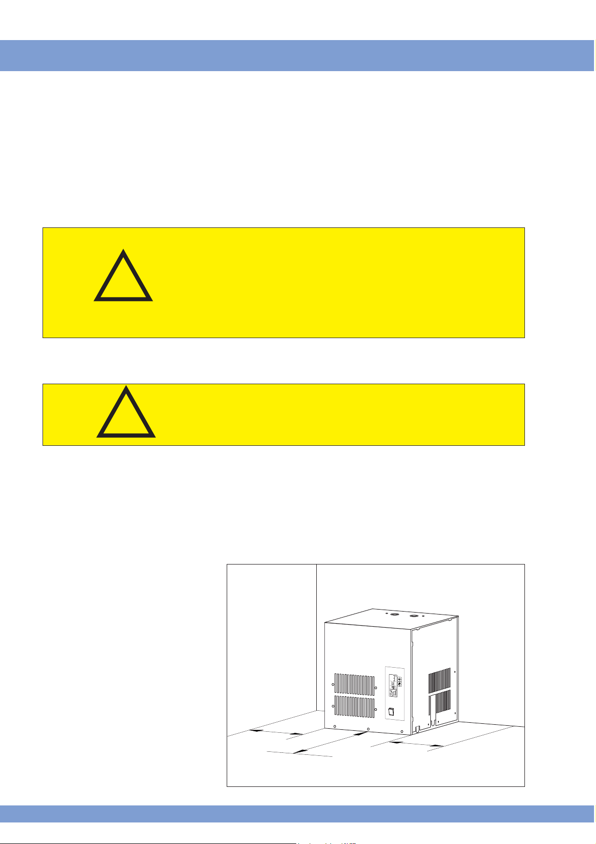
2.3 Installation
(mounting)
Fig. 1: Installation of
CA-dryer
Attention!
At different ambient conditions pay attention to the layout data!
The CA-dryer must be installed that accessibility to the
front panel is ensured. Furthermore leave space f or service purpose on both sides of the CA-dryer (fig. 1).
Wall mounting is possible with all types.
8
11.02
Page 9
Part 2 Installation
2.3.1 Version air cooled
2.4 Compressed air connection
!
The cooling air for the refrigerant condenser will be
sucked in at the front panel (fig. 5/3). This area must be
kept free and not be obstructed.
If necessary, sufficient cooling air supply must be provided by additional wall openings .
The cooling air outlet is positioned at the top of the unit
(fig. 5/8). Ensure a free air outlet and do not obstruct the
outlet of the cooling air.
If the CA-dryer is connected to an exhaust trunk, an additional fan must be installed to compensate the pressure drop. The controlling of the fan must be provided
through the CA-dryer.
The connection must be ex ecuted acc. to marking at the
CA-dryer (fig. 5/1+2).
For service purposes the installation of a bypass line is
recommended (additional equipment).
Attention!
Before mounting the CA-dryer, welding residual, rust or
other pollution must be removed from the pipelines to
be connected. If pollution cannot be excluded, proper
filter system must be installed
The compressed air pipes must be installed stress-free.
Expansion joints are recommended in case of vibrations
and pulsations.
2.5 Electric connection
The CA-dryers are completely equipped and wired. They
merely have to be connected to a power supply. The
CA-dryers are to be protected by slow-blow fuses as
defined in the wiring diagram.
Operation voltage: acc. to name plate or wiring diagram resp.
Attention!
Due to transportation reasons the power connection
cable with installed cable gland is located inside the casing of the CA-dryer.
After removal of the side wall (fig. 5/9) the cable gland
is mounted and fastened in the corresponding passage (fig. 5/6) of the casing.
11.02
9
Page 10
Part 2 Installation
2.6 Connection condensate drain
Attention!
A hose must be fixed at the condensate drain and led
out of the casing.
An opening (Fig. 5/7) can be used for leading out the
!
!
hose.
For safety reasons the side wall must be closed again.
The CA-dryer separates water as well as oil from the
compressed air. The water/oil mixture must not be led
into the sewage. Water and oil must be separated by
suitable separators (additional equipment).
Attention!
Route outflow so that persons or objects will not be struck
by condensate (condensate outlet with operating pressure)!
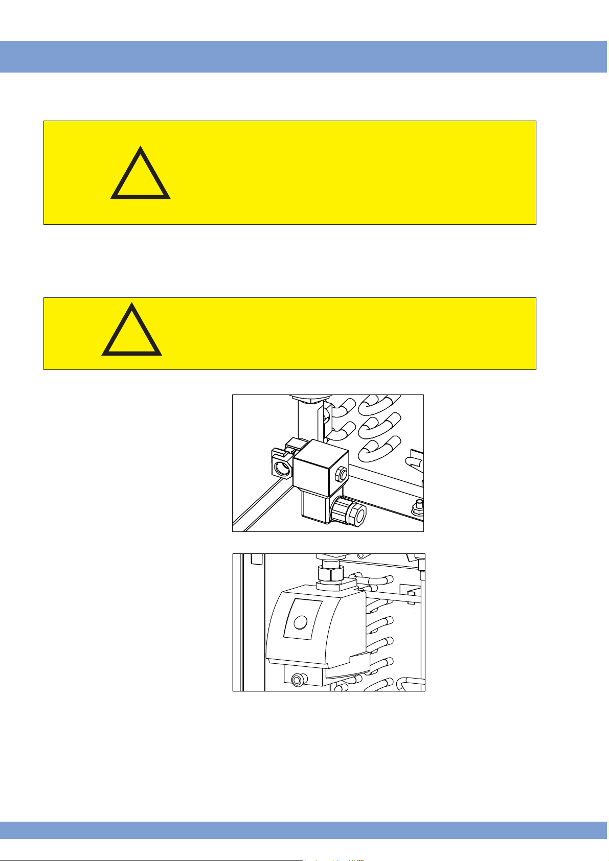
2.6.1 Version with solenoid valve
Fig. 2: Solenoid valve
2.6.2 Version with sensor
controlled drain
(option)
Fig. 3: Sensor controlled
drain
with electronic
regulated condensate drain
A minimum operation pressure of 2
bar is required for
safe oper ation.
10
11.02
Page 11

Part 2 Installation
2.6.3 Connection condensate draining
Fig. 4: Connection conden-
sate draining
The condensate drain pipe (fig. 2.1) may be fixed to the
wall with a rising slope of maximum 5 m. Thereby the
minimum operation pressure increases for 0,1 bar per
meter . The collecting pipe (fig. 2/2) should be laid throughout its whole length at least as the cross-section of the
condensate outlet.
2
1
from condensate drain
to treatment
11.02
11
Page 12

Part 3 Description
3.1 Designation
3.2 Purpose
3.3 Unit Layout
Fig. 5: Complete system
Refrigerating compressed air-dryer (CA-dryer).
Version see type code (page 2)
Compressed air will be dehumidified by the CA-dryer.
Following components of the CA-dryer are accessible
from outside (fig. 3).
12
9
8
Fig. 6: Electronic regulator
- operating panel
45 6 7
3
1 Compressed-air inlet
2 Compressed-air outlet
3 Cooling air inlet
4 Electronic regulator operating panel (Fig. 6)
5 Operation switch
6 Electric connection
7 Condensate drain
8 Cooling air outlet
9 Access for service
Data input key
Condensate draining key for
electronic regulated drain
Display electronic regulator
Operation switch
12
11.02
Page 13

Part 3 Description
3.3.1 Symbols
Fig. 7: Symbols
general
Operation switch “off”.
Compressed air inlet or outlet.
Before executing maintenance
work at the CA-dryer, the unit must
be disconnected from the power
supply.
If the CA-dryer is not disconnected
the risk of injuries is given, due to
free rotating fan wings.
The refrigerant compressor heats
up during operation so that there
is a danger of burns .
3.3.2 electronic regulator
symbols
Fig. 8: Symbols
electronic regulator
11
6
7
8
6
Condensate drain
1
1 Temperature in °C
2
2 Temperature in °F
3
3 Nor mal- or summer opera 4
5
9
tion
4 Percentage running time of
CA-dryer
5 Time to next condensate
draining
6 Failure indication
7 Condensate drain
8 Condensate tank
10
9 Maintenance interval ex-
ceeded
10 Counter working hours
12
11 Operation indication refriger
ant compressor
12 Actual energy consumption
Fig. 9: electronic regulator
operation
11.02
1 Data input key
2 Condensate drain key for
12
13
electronic regulated drain
Page 14

Part 3 Description
3.4 electronic regulator
Fig. 10: Normal display
electronic regulator,
example
The electronic regulator is a controller specially designed
for CA-dryers. It operates on the basis of micro
processors. Data as cooling temperature, pressure within
cooling circuit, ambient temperature as well as CA-dryer
specific parameter are processed by the electronic and
therewith the actual operational state of the unit is
determined.
If it is allowed due to the measuring data, the cooling
compressor is stopped for a predetermined time. The
pulsating measuring of the temperatures (multiple per
second) and the function of the aluminium-heat exchanger as cold store enables the quic k reaction on load
changes without allowing dew point peaks to e xceed the
max. adjusted nominal value.
Depending on loads the electronic regulator additionally
regulates the condensate drain to avoid compressed air
losses.
1
1 Pressure dew point
(shown Celsius)
3.4.1 Normal operation
(factory setting)
3.4.2 Summer operation
3.4.3 Automatic operation
2 Condensate level
4 lines = condensate
2
3
4
The electronic regulator sets the pressure dew point on
max. 3°C.
The electronic regulator sets the pressure dew point on
max. 7 °C.
The electronic regulator sets the pressure dew point in
dependence to the ambient temperature at the location,
to keep a relative humidity below 40% at the CA-dryer
outlet.
5
will be drained shortly
3 682 working hours
4 Refrigeration compressor
working
5 Actual energy consumption
is 50%
!
Attention!
To enab le this, it is necessary that the ambient temperature of the whole CA-network are not below the temperatures at the location of the CA-dryer.
14
11.02
Page 15

Part 3 Description
3.5 Nominal power of
CA-dryer
3.6 Principle of operation
The nominal power of the CA-dryer mentioned in the
technical data is related to a working pressure of 7 bar,
a compressed air inlet temperature of 35 °C as well as
an ambient temperature of 25 °C acc. to DIN ISO 7183.
Lower working pressure, higher compressed air inlet temperature and/or higher ambient temperatures overload
the compressor which causes to an increased pressure
dew point and the compressor can be stopped by internal safety devices.
At essentially deviating operation conditions , contact the
deliverer of the CA-dryer for support.
The CA-dryer includes a refrigerant system cooling the
compressed air flow. The steam saturation limit is lowered causing condensate to fall out, which is removed
by the condensate drain.
The higher the cooling temperature difference of the air,
the higher the amount of condensate.
The lower the cooling temperature of air, the lower the
moisture content.
The lower limit of air cooling results from the operating
principle of the CA-dryer based on the moisture separation in liquid form.
So the freezing point of water (0 °C) must not be undergone.
3.7 Mode of operation
3.7.1 Compressed air side
The compressed air precooled in the aftercooler and
saturated with moisture enters into the CA-dryer and is
precooled in the first cooling stage, the air-to-air heat
exchanger without additional energy. Cooling is carried
out in counterflow to the already cooled air heated during this process.
The cooling to the pressure dew point is perfor med in
the second cooling stage, the refrigerant-to-air heat exchanger cooled by the refrigerant system installed. Subsequently, the cooled compressed air is reheated in the
air-to-air heat exchanger as already described.
The pressure dew point is indicated at the electronic
regulator panel.
11.02
15
Page 16

Part 3 Description
3.7.2 Refrigerant side
3.8 Condensate draining
3.8.1 Condensate drain
electromagnetic
The refrigerant is injected into the refrigerant-to-air heat
exchanger where it ev aporates, thereby the compressed
air is cooled. The electronic regulator regulates the cooling temperature and keeps the pressure dew point constant in nearly all capacity stages.
The refrigerant compressed by the motor compressor is
condensed within the condenser and is availab le for the
evaporation again.
The condensate drain is used for draining the condensate.
Depending on the ambient- and cooling temperature of
the CA-dryer, the solenoid valve is opened by the
electronic regulator. This ensures a compressed air condensate draining with nearly no loss of compressed air.
If the condensate volume deviates from the set values
(see 4.6.1.6) the adaptation to the specific characteristics
of compressed air system is possible (see 4.6.1.6)
3.8.2 Condensate drain
sensor-controlled
(option)
Fig. 11: Condensate drain
reports
Once the container has filled with condensate, so that
the capacitive level sensor emits a signal, the internal
solenoid valve opens and the condensate is forced by
the working pressure into the discharge pipe.
The condensate drain electronic system ensures the
closing of the outlet opening before any compressed air
can escape. For functional safety a minimum pressure
of 2 bar is necessary.
Power
Alarm
Test
Power
Alarm
Test
Power
Alarm
Test
123
At faulty condensate discharge (bloc ked discharge pipe,
pressure below minimum operating pressure), the unit
changes to the alarm control after 60 seconds. The green
LED flashes and a potential-free contact is activated.
While in alarm control mode, the solenoid valve will open
ever y 4 minutes for a period of 7,5 seconds, in order to
remove any possible obstructions in the discharge pipe
automatically.
A unit filled during a pressureless state will additionally
be emptied automatically , as soon as the minimum pressure within the condensate drain has been reached.
16
11.02
Page 17

Part 4 Operation
4.1 Commissioning
4.2 Starting
4.3 Operation
After installation the CA-dryer is supplied with power via
the power cab le (fig. 5/1) or by operating the main s witch
(fig. 5/13).
Before operating the operation switch (fig. 3/14), a waiting period of at least 6 hours is absolutely necessary.
The CA-dryer is switched on via the operation switch
(fig. 5/14). After approx. 5 minutes the compressed air
admission is possible by connecting the compressed air
compressor.
The CA-dryer is designed for continuous operation and
may remain switched on during periods of no load, as it
adapts to the required performance automatically.
Operation is indicated by the luminous operation s witch
(fig. 5/14).
The electronic regulator shows the pressure dew point
reached by the CA-dryer.
4.4 Stopping
At standstill periods, the CA-dryer is switched off with
operation switch (fig. 5/5).
For service works, the CA-dryer is switched off by pulling the power cable (Fig 5/6).
At restarting proceed acc. to item 4.1.
11.02
17
Page 18

Part 4 Operation
4.5 electronic regulator
- operation
Fig. 12: Pressure dew point
Fig. 13: Percentage running
time of CA-dryer
Fig. 14: Condensate drain
Following operation data can be
recalled by operating the data
selector key ( ):
- Pressure dew point
- Summer operation
- Percentage running time of
CA-dryer in relation to total
running time of the system
- Next condensate drain in 3
minutes
4.6 Changing the factory
setting
Fig. 15: Changing factory
setting
1. Press data selector key ( )
for 5 seconds to change from
display- into change mode.
2. If necessary press data selector ke y ( ) sev eral times until
requested change mode
appears.
3. Adjusting by condensate drain
key ( )
4. Press data selector k ey ( )
for 5 seconds to sav e changes
and returning into display
mode.
18
11.02
Page 19

Part 4 Operation
4.6.1 Change modes
4.6.1.1 P01
4.6.1.2 P02
4.6.1.3 P03
4.6.1.4 P04
4.6.1.5 P05
4.6.1.6 P06
Activation pressure dew point-summer set value (factory setting: pressure dew point 7 °C).
Acknowledgement of failures (see 5.1)
Acknowledgement maintenance interval (see 5.1)
Change of pressure dew point-normal set value by serv-
ice.
Change of pressure dew point-summer set value by serv-
ice.
Change of station time of condensate draining time
(optimization of condensate draining)
At normal operation conditions the condensate volume
per condensate draining time corresponds to the values
mentioned below.
Type of CA-dryer Condensate volume
405 AP, 406AP: 40cm³ - 60cm³
407 AP: 12cm³ - 18cm³
!
4.6.1.7 P07
4.6.1.8 P08
4.6.1.9 P09
4.6.1.10 P10
Attention!
- at greater amount of condensate per condensate
draining time the factor P06 must be lowered.
- at smaller amount of condensate per condensate
draining time the factor P06 must be raised.
P06 Minimum: Factor 1
P06 factory setting: Factor 16
P06 Maximum: Factor 33
Setting possibility of the pressure dew point failure limit
value (factory setting 18 °C).
Change °C / °F.
Activation solenoid valve condensate draining.
Activation automatic operation.
11.02
19
Page 20

Part 5 Maintenance
5.1 electronic regulator
maintenance display
Fig. 16: Maintenance display
5.1.1 Acknowledgement
maintenance interval
Fig. 17: Acknowledgement
maintenance interval
Flashing maintenance symbol:
- maintenance interval exceeded
1. For acknowledgement press
data selector key ( ) within 5
minutes after restart the CADryer for 5
seconds.
2. Press data selector key ( )
seve ral times until change mode
P03 appears.
3. Acknowledging the maintenance
interval key with condensate
drain key ( ) - the maintenance symbol disappears ( ).
4. For returning into display mode
press data selector key ( )
for 5 seconds
5.1.2 Maintenance
!
5.1.3 Daily checks
(without maintenance symbol)
Attention!
Prior to any maintenance works all safety regulations for
electrical systems and units must be observed.
Maintenance intervals highly depend on the mode of
operation and the ambient conditions on site, the intervals belo w are only to be understood as general recommendations.
Monitoring of all temperatures.
Check function of condensate drain.
a) electronic regulated condensate drain :
Operating condensate drain key ( )
check, if water is drained.
b) Sensor controlled condensate drain:
Operating key “Test ”.
check, if water is drained.
When operated, the condensate drain pulses all
2-3 seconds.
20
11.02
Page 21

Part 5 Maintenance
5.1.4 Weekly maintenance
!
5.1.5 Cleaning of filter before condensate
drain with solenoid
valve
5.1.5.1 Dismounting of
filters
Inspection and cleaning of condensate draining system
if necessary.
Attention!
Maintenance work must be performed at the depressurized condensate trap only. For this purpose, the installation of a bypass line is recommended (additional
equipment).
a) disconnect CA-dr yer from compressed air system
b) remove side wall (Fig. 5/9)
c) shut ball valve
d) depressurize by operating the condensate drain
key (Fig. 9/2).
e) remove cap
f) remove filter and clean with neutral cleaning agent,
replace if necessary.
Fig. 17: Solenoid valve, ball
valve with filter
1
5
2
3
4
1 Ball valve with filter insert
2 Filter
3 O-ring
4 Cap
5 Solenoid valve
5.1.5.2 Mounting of Filters
5.1.6 Sensor controlled
condensate drain
(option)
11.02
Mounting is done in reverse order.
Replace working parts yearly (see spare par ts list)
21
Page 22

Part 5 Maintenance
5.2 Trouble shooting
Fig. 19: Failure indication
general
5.2.1 electronic regulator
failure indication
Fig. 20: electronic regulator
Failure indication
Failure indication: CA-dryer
stopped.
CA-dryer stopped
Display changes be-
tween set value and
failure indication
(refrigerant overpressure)
Cause
5.2.1.1 F1 sensor pressure
dewpoint defective
5.2.1.2 F2 sensor ambient
temperature defective
5.2.1.3 EH EEPROM:
electronic regulator
5.2.1.4 EL electronic regulator
defective
5.2.1.5 FH refrigerantoverpressure
5.2.1.6 EU low voltage
5.2.1.7 H1 dew point too high
Remedy
Check sensor connection, replace sensor
Replace regulator
Restart CA-dr yer, if not possible:
Replace regulator
Restart CA-dr yer, if not possible:
Replace regulator
See 5.2.5
Ensure electric power supply acc. to technical data.
See 5.2.4
5.2.1.8 L1 dew point too low
See 5.2.6.3
22
11.02
Page 23

Part 5 Maintenance
5.2.2 Acknowledgement of
failures
Fig. 21: Acknowledgement of
failures
5.2.3 Function:
Cause
No function
1. For acknowledgement operate
data selector key ( ) for 5
seconds.
2. Operate data selector key ( )
once more until P02 appears .
3. Acknowledgement of failure
through condensate drain
key ( )
4. For returning into display mode
press data selector key ( )
for 5 seconds.
Remedy
- Check and establish power supply if necessary
- If the pow er supply is ok, call for service or send CAdryer to the manufacturer.
5.2.4 Water in compressed
air system
Cause
5.2.4.1 Condensate is not
drained properly
5.2.4.2 electronic regulated
condensate drain
5.2.4.2.1 Faulty condensate
draining
5.2.4.2.2 Solenoid valve de-
fective
Remedy
- check condensate separator behind the compressor.
- possibly install automatic drain
- no sufficient drainage of the condensate separator
behind the compressor, extend condensate draining
time.
Clean solenoid valve
Replace solenoid valve
11.02
23
Page 24

Part 5 Maintenance
5.2.4.3 Sensor-controlled
condensate drain
5.2.4.3.1 Blocked discharge
pipe
5.2.4.3.2 Operation pressure
below required minimum
Cause
5.2.4.4 Temporary overload of
the CA-dryer due to
non-uniform compressed air consumption
5.2.4.5 Overload due to high
volume flo w, or too high
compressed air inlet
temperature
Clean condensate drain with neutral cleaning agent.
Increase working pressure
Remedy
Reduce load, check whether CA-dryer´s capacity is properly selected
Reduce CA-consumption or increase CA-dryer´s capacity
(with installed bypass line)
5.2.4.6 Bypass valv e of bypass
line opened
5.2.4.7 Bypass valv e of bypass
line leaky
Close bypass valve in the bypass line
Seal or replace bypass valve in the bypass line,
24
11.02
Page 25

Part 5 Maintenance
5.2.5 Stopping CA-dryer
during operation:
Cause
Remedy
- Stopping of CA-dryer by
installed electric star t and
protection device (Klixon) at
the refrigerant compressor
due to overload
5.2.5.1 CA-volume flow too
high
5.2.5.2 CA-inlet temperature
too high
5.2.5.3 Room temperature too
high
5.2.5.4 Defectiv e fan or cooling
water regulator (watercooled version)
- eliminate cause of trouble, see 3.5 or call for service
- the CA-dryer will return to operation mode automatically after protection device has cooled down.
Note: The immediate restarting of the unit is not possible because the protection device requires a minimum time to cool down to an admissible operating
temperature.
Reduce volume flow
Check whether CA-dryer´s capacity is properly selected,
increase CA-dryer´s capacity
Check aftercooler with separator and drain behind the
compressed air compressor, install if not present
Ensure proper ventilation of CA-dryer´s location
Replace fan or cooling w ater regulator resp., call for service
5.2.5.5 Condenser polluted
5.2.5.6 Operating pressure too
low
Clean condenser
Increase operating pressure, chec k whether CA-dryer´s
capacity is properly selected
11.02
25
Page 26

Part 5 Maintenance
5.2.6 High differential
pressure at CA-side:
Cause
5.2.6.1 Compressed air volume
flow too high
5.2.6.2 Working pressure too
low
5.2.6.3 Icing of CA-dryer
Remedy
Check whether CA-dryer´s capacity is properly selected,
increase CA-dryer´s capacity
Increase operating pressure , check whether CA-dryer´s
capacity is properly selected
Characteristics: - differential pressure at com-
pressed air side increases
- volume flow decreases
Disconnect unit and maintain compressed air flow . After
approx. half an hour, the differential pressure will return
to normal value. Restar t the unit. If the heat exchanger
ices up again call for service.
26
11.02
Page 27

7 bar
2002-11-29 1
+35°C
3
m³/h 50 65 80
m³/min 0,83 1,08 1,33
450
0,036
2 / 16
16 / 50
bar
500
450
450
0,33
< 70
20
1/4"
+3°C
+25°C
max. +60°C
min. + 2°C
max. +50°C
405AP - 407AP
Type-No.: Date: Page 1 of
Size of Housing
low pressure side,
high pressure side
height
width
depth
at compressed air inlet temperature
operating pressure
ambient temperature
pressure dew point at CA-dryer outlet
Power consumption at ambient temperature
Compressed air inlet temperature
Volume flow reffered to the suction status of the air compressor
Pos.1 : +20°C 1 bar
Pos. 3, 4: +25°C
Allowed ambient temperature:
Technical modifications are subject to change without notice!
Refrigerated Compressed Air Dryer I1T 5003 0GB
Designation: Technical Data Sheet:
GB Technical Data
Pos. Type-No. 405 AP 406 AP 407 AP
1 Volume flow
3 Power consumption (total) kW 0,25 0,27 0,33
Power supply 230V 1N~
4 Power consumption (fan) kW
5 50 Hz
6 Allowable pressure (compressed air) min./ max. bar
Cooling air required
2 m³/h
Allowable pressure
(refrigerant)
Compressed air connections 3/4
Weight
7
8 G
9 kg 40 41 44
10 Dimensions mm
11 Refrigerant quantity R 134a kg 0,37
Condensate drain
Sound pressure level
Type of protection
12 dB (A)
13 IP
14 G
Specification:
Page 28

/2.1*
L1.1
A
/2.1*
N1.1
B
C
D
E
F
1
/2* Bl.
1
Blatt
von
+
=
only for options
*: nur fuer Optionen
13
15
R1
Regler Kälte-Drucklufttrockner
NTC-resistor
NTC-Widerstand
A1
Y1
A2PE
(A100)
Kondensatablass
condensate drain
E2A0405000
Zeichn.Nr./drawing no.
405AP-406AP
Typ:
2
A1
11
M
M2
K1
10
(V100)
Kälteverdichter
fridge compressor
1
fan
(M200)
Ventilator
L1L1 PEN PEN
X0
max.
10A
13.01.03
Datum
supply by plug
220-230V1N~/50Hz
Einspeisung durch Netzstecker
a0405000
Urspr. Ers. f.
Kälte-Drucklufttrockner
refrigerated dryer
RAH
DIN 40719
JN
Bearb.
Gepr.
NormNameÄnderungZustand Datum
1 2 3 4 5 6 7 8
1213 PE
M
1
C1
4
1
P>
A2
1 3 4 5 6 7 8 9 10 11 12
14
M1
L
N
S4
4
1
S1
(PS)
manostat
Pressostat
2 3 4 5 6 7 8
5
2
1
Betr.-schalter
operation switch
A
B
C
D
E
F
Page 29

/2.1*
L1.1
A
/2.1*
N1.1
B
C
D
E
F
1
/2* Bl.
1
Blatt
von
+
=
only for options
*: nur fuer Optionen
13
15
R1
Regler Kälte-Drucklufttrockner
NTC-resistor
NTC-Widerstand
A1
Y1
A2PE
(A100)
Kondensatablass
condensate drain
E2A0407000
Zeichn.Nr./drawing no.
407AP-409AP
Typ:
2
K1
RS PE
M
1
A1
4
1
P>
A2
C
1 3 4 5 6 7 8 9 10 11 12
1 N
3
1
M1
L
N
L
XM
S4
4
1
S1
(PS)
manostat
Pressostat
2 3 4 5 6 7 8
5
2
1
N
1 2
C1
M
1
(V100)
Kälteverdichter
fridge compressor
fan
(M200)
Ventilator
a0407000
Urspr. Ers. f.
Kälte-Drucklufttrockner
refrigerated dryer
13.01.03
RAH
DIN 40719
JN
M2
Datum
Bearb.
Gepr.
NormNameÄnderungZustand Datum
L1L1 PEN PEN
X0
max.
10A
supply by plug
220-230V1N~/50Hz
Einspeisung durch Netzstecker
1 2 3 4 5 6 7 8
Betr.-schalter
operation switch
A
B
C
D
E
F
Page 30

Remarks Order quantityDenomination Dryer type Short description IdentnumberP&I diagram
405 AP-407 AP I17 5003 0GB 2002-12-02 1
Type-No.: Sheet No.: Date: Page 1 of
Details by the manufacturer Details by the user
Wiring diagram Qty. Unit
GB Spare Parts List DIN 24 420
S1 1 Pcs. Operation switch 405AP-407AP 0108673000
A100 Y1 1 Pcs. Condensate Drain Solenoid Valve 405AP-407AP 0101775000
A102 1 Pcs. Drain Valve with Filter 405AP-407AP 0111713000
EICA A2 1 Pcs. Elektronic regulator 405AP-407AP 0111822405 - ...407 Type No. Coded
PS00 S2 1 Pcs. Fan pressostat 405AP-407AP 0103087000
M200 M2 1 Pcs. Fan motor 405AP-407AP 0102404000
Refrigerated Compressed Air Dryer
Denomination:
Page 31

D DEUTSCH ENG ENGLISH
Ñ
Ê
ÖRSÄ
A
KONFORMITÄTSERKLÄRUNG DECLARATION OF CONFORMITY
Wir erklären in alleiniger Verantwortlichkeit, dass dieses Produkt mit
den folgenden Normen übereinstimmt* gemäß den Bestimmungen der
Richtlinien**
F FRANÇAIS NL NEDERLANDS
DECLARATION DE CONFORMITE CONFORMITEITSVERKLARING
Nous déclarons, sous notre seule responsabilité, que ce produit est en
conformité avec les normes ou documents normatifs suivants* en vertu
des dispositions des directives **
We herewith declare in our sole repsonsibility that this product complies
with the following standards* in accordance with the regulations of the
undermentioned Directives**
Wij verklaren als enige verantwoordelijke, dat dit product in
overeenstemming is met de volgende normen*
conform de bepalingen van de richtlijnen**
IT ITALIANO ES ESPA
DICHIARAZIONE DI CONFORMITÀ DECLARACION DE CONFORMIDAD
Noi dichiariamo sotto la nostra esclusiva responsabilità che il presente
prodotto è conforme alle seguenti norme* in conformità con le
disposizioni delle normative **
PT PORTUGU
DECLARAÇÃO DE CONFORMIDADE
Declaramos sob nossa responsabilidade que este produto está de
acordo com as seguintes normas* de acordo com as directrizes dos
regulamentos **
FIN SUOMI NO NORGE
VAATIMUKSENMUKAISUUSVAKUUTUS SAMSVARSERKLÆRING
Vakuutamme, että tämä tuote vastaa seuraavia normeja* on direktiivien
määräysten mukainen**
DA DANSK POL POLSKI
OVERENSSTEMMELSESATTEST OŚWIADCZENIE O ZGODNOŚCI
Hermed erklærer vi på eget ansvar, at dette produkt stemmer overens
ed følgende standarder* iht bestemmelserne i direktiverne**
EL ΕΛΛHNIK
∆ΗΛΩΣΗ ΑΝΤΙΣΤΟΙΧΕΙΑΣ MEGEGYEZŐSÉGI NYILATKOZAT
∆ηλώνουµε µε ιδία ευθύνη ότι το προϊόν αυτό αντιστοιχεί στις
ακόλουθες προδιαγραφές*
σύµφωνα µε τις διατάξεις των οδηγιών**
S SV SVENSKA
Declaramos bajo nuestra exclusiva responsabilidad, que el presente
producto cumple con las siguientes normas* de acuerdo a lo dispuesto
en las directrices**
F
Vi försäkrar på eget ansvar att denna produkt överensstämmer med
följande standarder* enligt bestämmelserna i direktiven**
Vi erklærer under eget ansvar at dette produkt samsvarer med følgende
normer* henhold til bestemmelsene i direktiv**
Oświadczamy z pełną odpowiedzialnością, że niniejszy produkt
odpowiada wymogom następujących norm* według ustaleń wytycznych
**
HU MAGYAR
Kizárólagos felelősségünk tudatában ezennel igazoljuk, hogy ez a
termék kielégíti az alábbi szabványokban lefektetett követelményeket*
megfelel az alábbi irányelvek előírásainak**
OL
KRAN OM ÖVERENSSTÄMMELSE
Druckluftkältetrockner
Cool 201 - Cool 401
EN 292, EN 294, EN 378-1, prEN 387 -2, EN 60204-1, EN 60335-2-40, EN 50081, EN 50082
** 98/37/EG, 73/23/EWG, 89/336/EWG
Ing. grad. H. J. Schaller
Entwicklungsleiter
Metabowerke GmbH
Business Unit Elektra Beckum
Daimlerstr. 1
D - 49716 Meppen
Meppen, 12.06.2003 1001117
 Loading...