

Page 1
U1A0168.fm
091 001 8442
3
5
2
5
1
5
0
5
9
4
8
4
7
4
6
4
5
4
4
4
3
4
2
4
1
4
Tischverbreiterung . . . . . . . . . . . . . . . . . . .3
Table Extension . . . . . . . . . . . . . . . . . . . . . .5
Rallonge latérale de table . . . . . . . . . . . . . .7
Tafelverbreding . . . . . . . . . . . . . . . . . . . . . .9
Allargamento del tavolo . . . . . . . . . . . . . . .11
Extensión de la mesa . . . . . . . . . . . . . . . .13
Alargador da bancada . . . . . . . . . . . . . . . .15
115 161 1687 / 1001 - 5.0
Bordforbredelse . . . . . . . . . . . . . . . . . . . . .17
Bordforlengelse . . . . . . . . . . . . . . . . . . . . .19
Tillsatsbord - bredd . . . . . . . . . . . . . . . . . .21
Pöydän levennys . . . . . . . . . . . . . . . . . . . .23
Asztalszélesítő . . . . . . . . . . . . . . . . . . . . . .25
Poszerzenie stołu. . . . . . . . . . . . . . . . . . . .27
Πεπλτυνση του πγκου . . . . . . . . . . . .29
Page 2
U
ELEKTRA BECKUM
XA0028E1.fm Operating Instruction ENGLISH
ENGLISH
1. Please Read First!
• Read these instructions before use.
Also observe the instructions for the
circular saw, the safety instructions
in particular.
2. Mounting Locations
1
2
34
Note:
3
This table side extension is
intended for laterally extending the support area of the circular saw table (1). In
order to be able to install the table side
extension, the Base System Rails (2) fitting the saw must be installed.
The table side extension can be fitted
either to the left (4) or right (3) hand side
of the saw table. The scale supplied are
intended for installation on the right hand
side, as the sliding carriage can be
intalled on the left hand side.
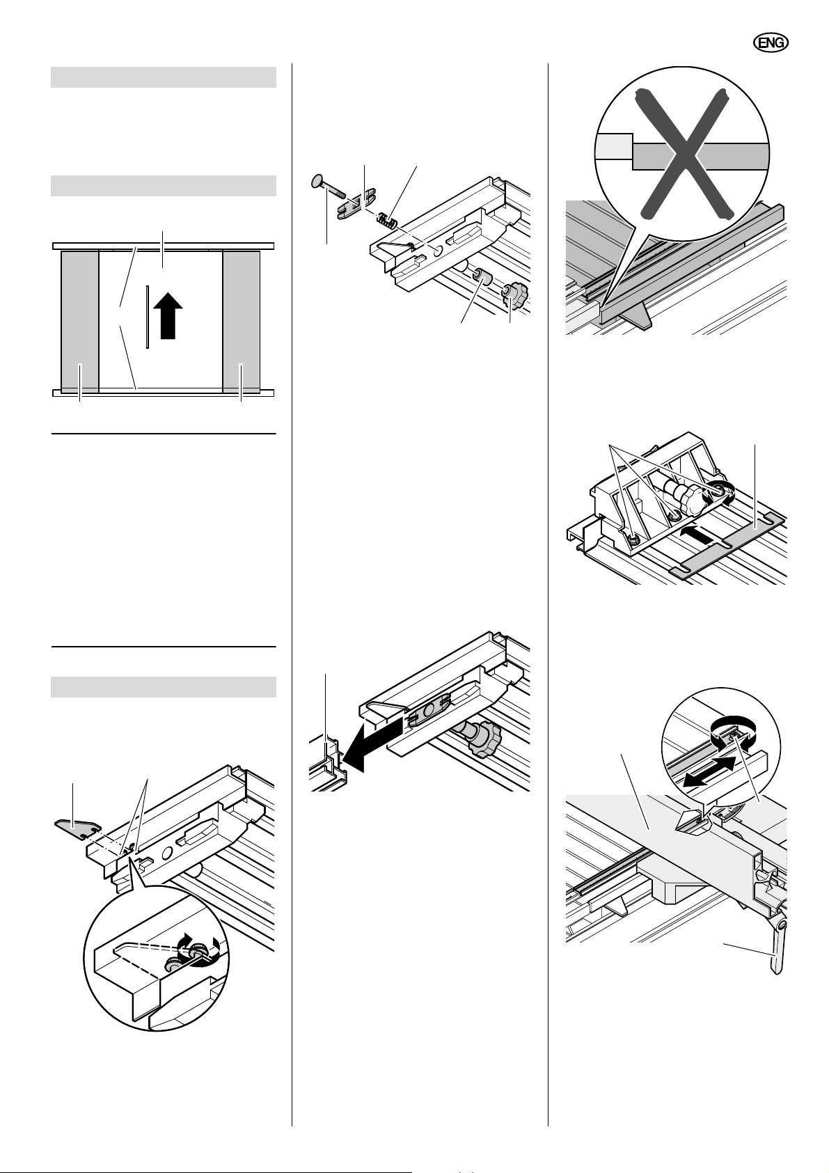
3. Assembly
1. Slide pointer (5) under the two
screws (6) as illustrated and tighten
both screws.
2. Put both clamping plate (7) and coil
spring (8) on the carriage bolt (9) as
ilustrated: The offset ends of the
clamping plate must point towards
the carriage bolt's head.
78
9
10 11
3. Insert carriage bolt (with fitted
clamping plate and coil spring) from
the outside into the hole of the side
extension's mounting rail.
4. Put distance sleeve (10) from inside
on the carriage bolt and screw on
knurled thumb nut (11), but do not
yet tighten it.
5. Repeat steps 2. though 4. on the
other end of the table side extension.
6. Slide table side extension into the
two extrusions (12) of the base system rails: The table side extension
must be pushed at both ends fully
against the saw table.
12
ELEKTRA BECK
53
52
51
50
49
48
47
46
45
44
43
42
41
39
39
If the table side extension is too low:
Loosen screws (13) on the underside
and slide one or more shim plates (14)
below the table extension's mounting
rails. Tighten screws (13).
13 14
Scale alignment
1. Position rip fence (15) at the approximate centre of the table side extension and lock with ratchet lock lever
(16).
15
56
7. Tighten knurled thumb nuts (11).
Caution!
A
The table side extension must
be exactly level with the saw table,
otherwise workpiece and rip fence
may get caught by the step or rock.
17
ELEKTRA BECKUM
34
33
32
31
30
29
28
27
26
25
24
23
22
20
16
2. Make trial cut: Place workpiece
against rip fence and make a cut.
3. Measure the width of the workpiece
(from edge of cut to rip fence).
4. Loosen fixing screw (17) of the table
side extension's scale.
5
Page 3

ENGLISH
3
75
76
74
73
72
71
6
5. Move scale, until the value indicated
by the left-hand edge of the rip
fence corresponds with the value
measured at the workpiece.
6. Tighten scale fixing screw (17)
again.
7. Set rip fence exactly to 320 mm (for
UK 220 and PK 200) or 520 mm (for
PKF 255) and lock it in position.
8. Loosen scale fixing screw (18) of the
base system rail.
18
76
75
74
73
72
71
52
51
50
4
40
39
ELEKTRA BECKUM
43
42
41
49
48
47
46
45
44
A
B
A = B
1. Set rip fence exactly to 320 mm (for
UK 220 and PK 200) or 520 mm (for
PKF 255) and lock it in position.
2. Loosen knurled nuts on underside of
the table side extension and set
table extension (with the rip fence)
to desired width. The cutting width is
indicated by the base system rail's
scale.
3. Tighten knurled nuts on underside
of table extension again.
4. Place workpiece against rip fence
and perform the cut.
9. Move the base system rail's scale
(19), until the value indicated by the
table extension's pointer (20) corresponds exactly with the rip fence
distance (320 mm or 520 mm
respectively).
33
32
31
30
29
28
27
26
25
24
23
22
20
32
37
36
35
34
33
20
10. Tighten scale fixing screw (18)
again.
4. Operation
Risk of Kickback!
A
The rip fence's fence extrusion must always be exactly parallel
with the saw blade. Otherwise there is
a risk of the workpiece jamming between saw blade and rip fence, causing it to be kicked back against the
operator.
6
34
19
41
40
39
38
4
45
44
43
42
 Loading...