

ELEKTRA VCD25, VCD25/400V Installation Manual
www.elektra.eu
ELEKTRA
• VCD25
• VCD25/400 V
Heating
Cables
Instrukcja montażu
PL
Installation manual
UK
Инструкция по монтажу
RU

Applications
ELEKTRA VCD25 heating cables are intended for
prevention of snow and ice deposition on:
• driveways, roads, parking spaces and terraces,
• viaducts, bridges, loading ramps,
• stairs.
The heating cables are laid depending on the
type of surface:
• in the layer of sand or dry concrete – for the
asphalt, agstones or paving cobbles surfaces,
• directly in concrete – for the concrete slabs
or reinforced concrete surfaces.
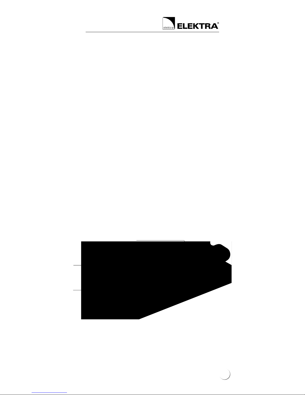
Heat resistant PVC outer sheath
Tinned copper braiding
PET covered aluminum foil shield
XLPE insulation
Multi-wire
heating core
ELEK TRA VCD heating cable structure
3
ELEKTRA
Heating Cables
Characteristics
of the heating cables
• The heating cables are produced
in ready-made units of the following lengths:
ELEKTRA VCD25 from 4.5 up to 142 m,
ELEKTRA VCD25/400 V from 8 up to 250 m,
• The cables are terminated at one end with
a 2.5 m-long power supply conductor,
and a connecting joint at the other,
• Specic heat output: 25 W/m,
• Power supply voltage:
– 230 V, 50/60 Hz for ELEKTRA VCD25,
– 400 V, 50/60 Hz for ELEKTRA VCD25/400 V,
• External dimensions: ≈ 5 x 7 mm,
• Min. installation temperature: -5°C,
• Min. cable bending radius: 3.5 D,
• Heating cables are screened, and their mains
connection via a residual current device constitutes effective anti-shock protection.
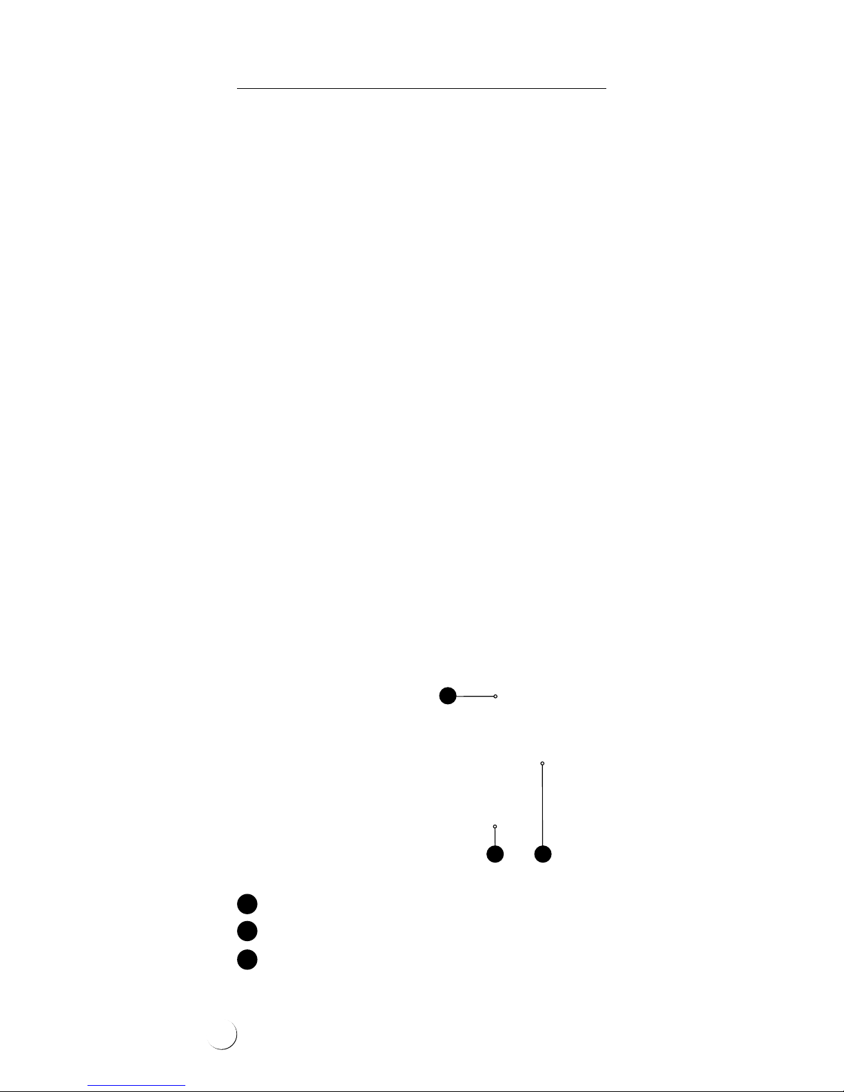
• “cold” power supply conductor
• double-core ELEKTRA VCD heating cable
• connecting joint between the power supply
conductor and the heating cable
1
2
3
1
2 3
4

Single-side powered
heating cables
Self-adhesive label
Note:
VCD25 heating cables are designed for the rated
voltage 230 V, 50 Hz, and VCD25/400 heating
cables – for the rated voltage 400 V, 50 Hz.
Heating cables’ power output may vary with +5%
and -10% from the label values.
!
The label features the following pictograph:
Note:
Never cut the heating cable.
Never trim the heating cable, only the power
supply conductor may be trimmed if required.
Never squash the “cold tail”.
Do not ever undertake on your own any attempts
to repair the heating cables, and in case any
damage is detected, report the damage to
an ELEKTRA authorized installer.
Never stretch or strain the cable excessively,
nor hit it with sharp tools.
Do not install the heating cables when ambient
temperature drops below -5°C.
Never lead the end joint and the connecting joint
between the heating cable and the power supply
conductor out of the surface. Both joints must be
placed - depending on the type of surface - within
the layer of sand, dry concrete or directly in concrete.
!
5
ELEKTRA
Heating Cables
Note:
Heating cables must be installed according
to the Instructions.
Mains connection of the heating cables should
be performed by an authorized electrician.
!
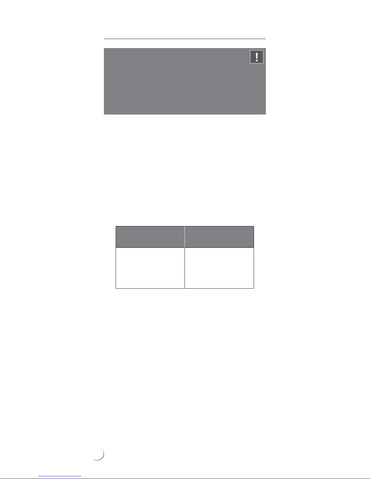
General information
When protecting external areas from snow and
ice deposition, it is required to assess the required
heat output value per m
2
of the surface. Recommended heat output depends on the regional climate conditions, i.e. minimum ambient temperature, snowfall intensity and wind strength.
Higher output is required if the heated area is:
• exposed to low temperatures,
• exposed to wind operation from below:
bridges, stairs, loading ramps, overpasses,
• located in regions of intense snowfall.
Applying insulation layer to the surfaces exposed
to wind operation from below can improve the
effectiveness.
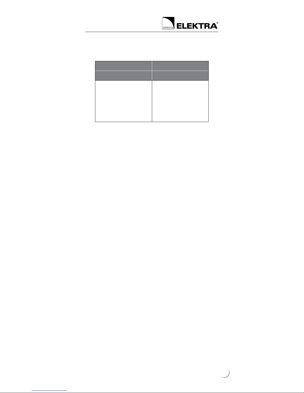
Ambient
temperature
Heat output
[W/m
2
]
> -5°C
-5°C ÷ -20°C
-20°C ÷ -30°C
< -30°C
200
300
400
500
6
Depending on the cable spacing, it is possible to
obtain required output per m
2
of the heated area.
Cable spacing cannot drop below 5 cm.
To protect large areas against snow and ice deposition, one option is application of 400 V voltage
heating cables, which would evenly load the electric circuit. Application of such cables would also
facilitate installation works, limiting the required
number of heating units.
Heat output 25 W/m
[W/m
2
] [cm]
250
300
350
400
500
10
8
~7
~6
5
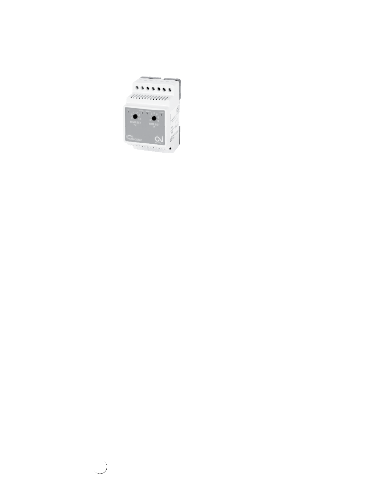
Controls
Properly selected control system will ensure adequate operation of the system only during snowand freezing rainfall. A controller with a temperature and moisture sensor will automatically
recognize the weather conditions. The system will
be then kept on standby and only switched on
when actually necessary. For this purpose, DINbus installed controllers ELEKTRA ETR2 and ETO2
can be applied.
7
ELEKTRA
Heating Cables
Snow & ice protection controls
ELEKTRA ETR2G controller – max. load up to 16
A, total output of installed heating cables must
not exceed 3600 W. As standard, equipped
with one temperature and moisture sensor with
installation tube.
ELEKTRA ETOG2 controller – max. load up to 3x16 A.
For applications in extended heating systems.
As standard, equipped with one temperature and
moisture sensor and an installation tube.
Additional temperature and moisture sensor can
be connected to this controller, which will enable
protection of two outdoor areas. Enables control
of two independent zones, e.g. garage driveway
and gutters, with one controller.
8

To maintain xed positioning of the cable and
steady spacing conforming to the calculated values,
the cables need to be attached with the ELEKTRA
TME installation tape (the tape should be positioned with the distances of 40 cm) or installation
mesh of 50 mm x 50 mm grid, made of Ø 2 mm
wire.
The heating cable layout should be commenced
from the side of the power supply conductor,
in such a way to enable easy reach to the switchboard.
If prolonging proved necessary, it is to be made
with a heat shrink joint, ensuring that the connection is safely sealed.
TME installation tape
Installation
Stage 1: Heating cable’s
installation
Before commencing the installation of the system, it is required to assess the necessary heat
output per m
2
, as well as calculate the required
spacing of the heating cable.
In order to calculate the required heating cable’s
spacing, apply the following formula:
a- a=S/L
where:
a-a: distances between cables,
S: surface area, for the surface heated with the heating cable,
L: heating cable’s length
9
ELEKTRA
Heating Cables
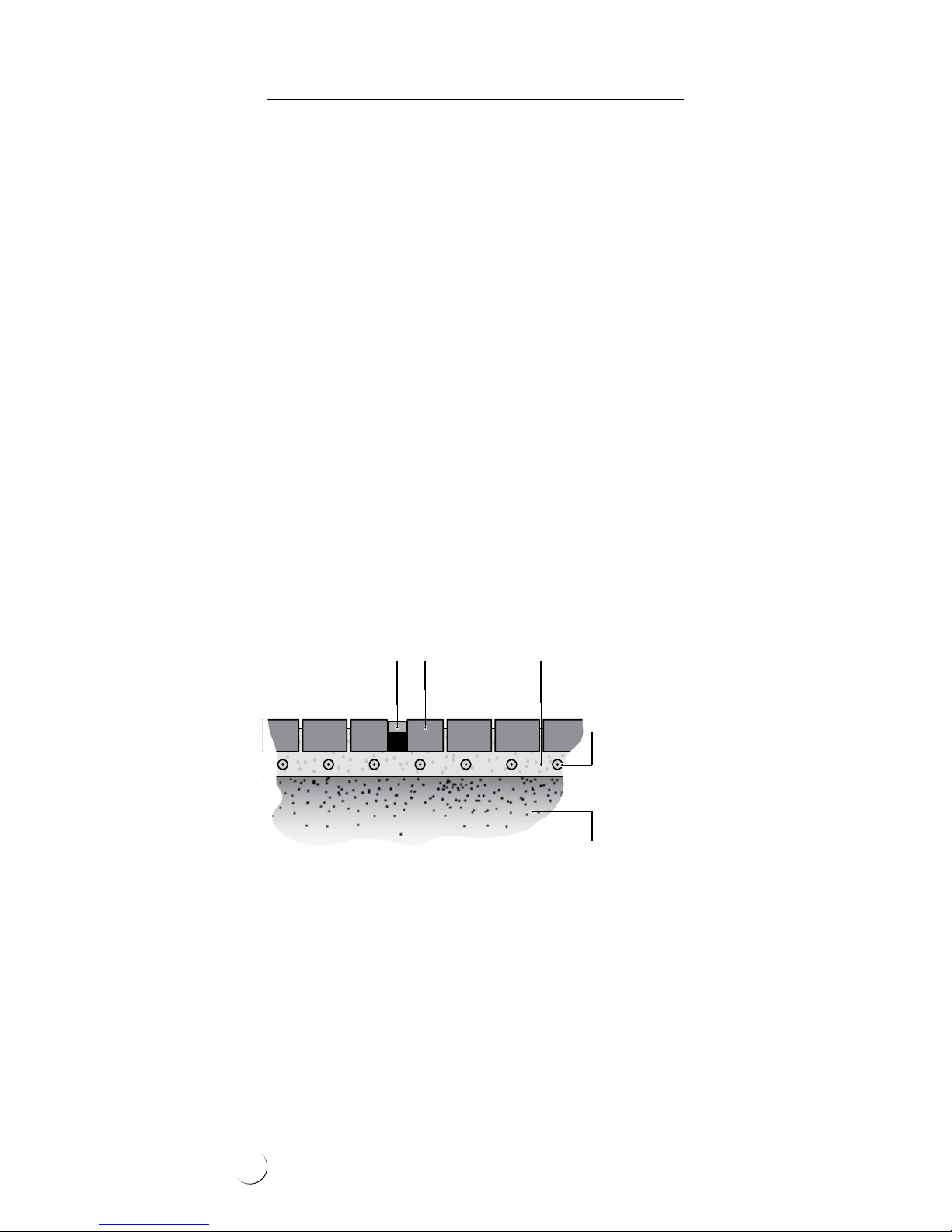
Cross section of pavement or driveway made from
agstones or paving cobbles
The heating cable layout will depend from the
surface type.
Asphalt, agstones
or paving cobbles surfaces
Stages of works:
• the hard concrete core base that is covered
with a layer of sand or dry concrete of the
min. 30 mm thickness (min. 50 mm for the
asphalt surfaces), and then compacted,
• ELEKTRA TME installation tapes or installation
mesh are laid on the layer of the compacted
sand or dry concrete, the heating cable fastened to them,
• the cables are completely covered with a layer
of sand or dry concrete,
• the nishing surface works follow – stage 4.
ELEKTRA VCD
heating cable
Compacted
base
Sand
or sand-cement sub-crust
min. 30 mm
Paving cobbles
or flagstones
Temperature
and moisture sensor
in installation tube
10

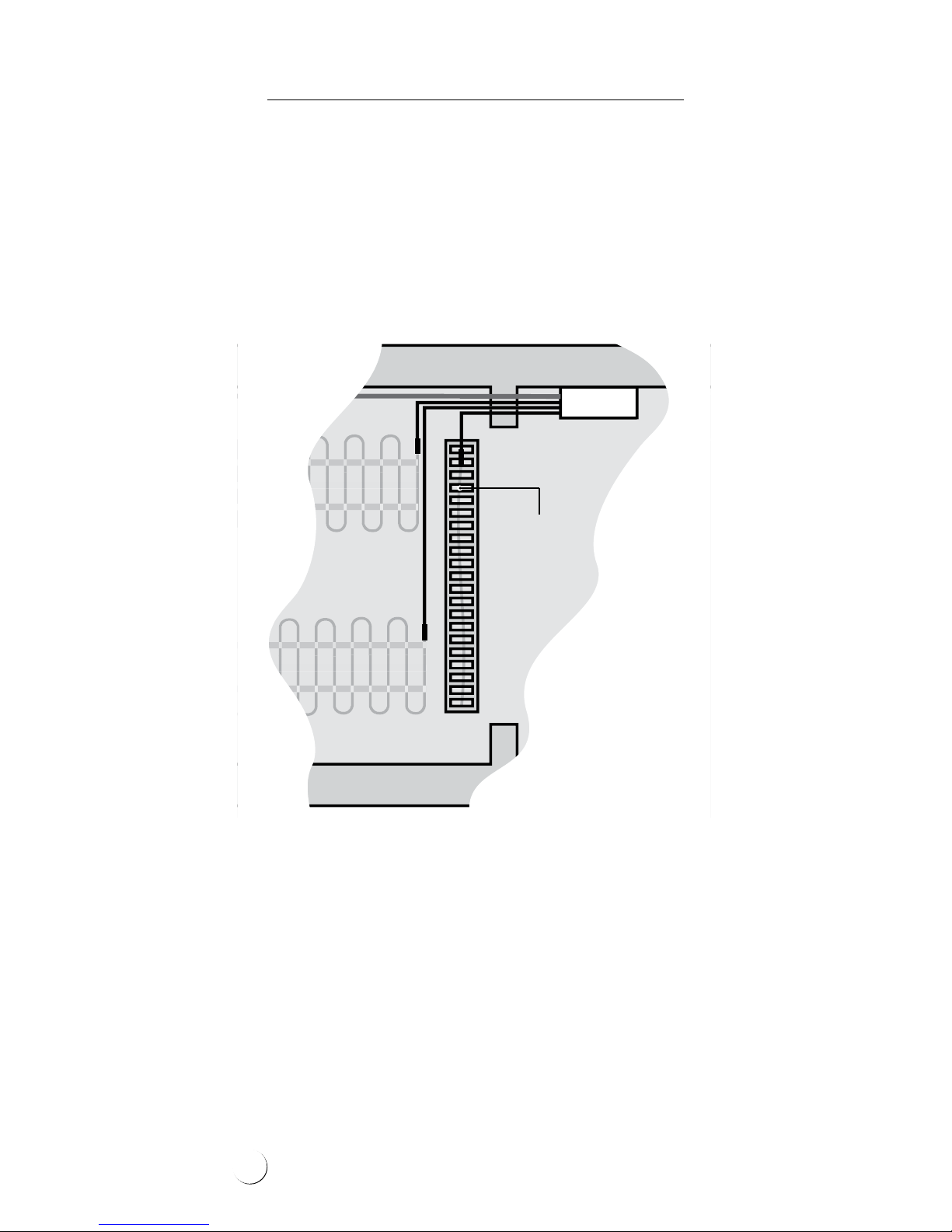
Example of ELEKTRA VCD25 heating cables as laid
in the garage driveway made from paving cobbles
11
ELEKTRA
Heating Cables
When protecting garage driveways against snow
and ice, it is not necessary to heat the entire
surface, but only the tyre tracks. The temperature
and moisture sensor should be placed within the
heated area, but not directly in the tyre tracks
under the car tyres’ path – in order to avoid snow
accumulation and unnecessary operation of the
heating system.
It is also necessary to heat the oor drain (drainage) in order to ensure the outow of water origi-
nating from snow melting. For this, use ELEKTRA
Self Tec
®
33 self-regulating cable. Place the cable
at the through bottom, enter the cable’s end into
the drainage down to 0.5 m – 1.0 m deep.
The heating circuit should be connected to the
power source in the electric board of the driveway, so that it is switched on simultaneously
with the remaining heating circuits.
Driveway
Garage
Heating
cable
Linear drainage heating
12

Concrete surfaces
Concrete surfaces require expansion joints.
Unreinforced concrete slabs should be divided
into expanded areas of the surface no larger
than 9 m
2
, reinforced concrete agstones into
areas no larger than 35 m
2
. The length of the
heating cables should be selected so that they
do not cross the expansion joints. Only the
power supply conduits (“Cold Tails”) can cross
the expansion joints. The Cold Tails are installed
in a metal protective conduit of the length of
approx. 50 cm.
Unreinforced concrete surfaces
Stages of works:
• the compacted base is levelled,
• ELEKTRA TME installation tapes or installation
mesh are laid on the compacted base,
the heating cable is fastened to them,
• the concrete slab works follow – stage 4.
Cross section of pavement or driveway
made of concrete slab
ELEKTRA VCD
heating cable
Temperature
and moisture sensor
in installation tube
Compacted
base
Concrete slab
min. 50 mm thick
Expansion
joint
13

ELEKTRA
Heating Cables
Reinforced concrete agstones
Heating cables can be fastened to the reinforce-
ment of the ferroconcrete agstones. Alternatively,
the installation mesh of 100 mm x 100 mm grid
made of Ø 4 mm wire can be applied, which
would facilitate maintaining steady spacing of
the cable, conforming to the calculated values.
Applying thermal insulation layer to ferroconcrete
agstone surfaces exposed to wind operation
from below (ramps, bridges, overpasses) can improve the system’s effectiveness.
VCD
heating cable
Roadway layer
(e.g. resin, quartz)
Reinforcement
of the ferr
oconcrete
flagstone
Metal mesh
Layer of plaster,
e.g. acrylic,
on plastering mesh
Thermal
insulation
Cross section of a suspended loading ramp
14

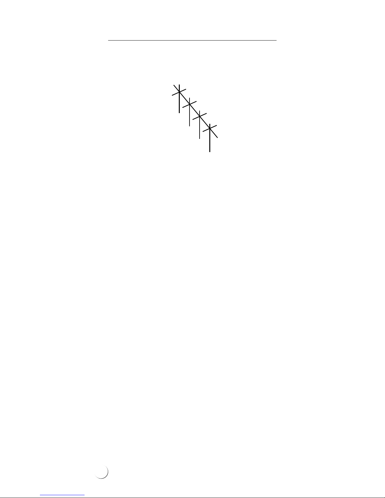
Stairs
Heating cables are laid in steps, placed in dedicated
previously chiseled grooves, and then covered
with concrete. The grooves are optimally made
at the stage of stairs construction. This method
of installation would greatly facilitate later
surface nishing works and would not cause
surface elevation.
If such elevation is acceptable (e.g. in any already existing stairs), then the cables will be
placed directly on the steps and xed to their
surface with the ELEKTRA TME installation tape
or installation mesh.
As substeps are not heated, outermost segments
of the cable need to be positioned as close to
the step’s edge as possible.
15
ELEKTRA
Heating Cables
Example of the heating cable layout on the steps
Laying thermal insulation on the steps and landings of the stairs will increase efciency (by shortening the warm-up time), which will decrease the
system’s operation costs.
80 mm
80 mm
80 mm
16

Stage 2: After the heating
cable has been laid
At this stage, it is necessary to undertake the
following steps:
• stick into the Warranty Card the self-adhesive
label, positioned on the power supply conductor of the heating cable,
• in the Warranty Card, prepare asketch of the
heating cable’s layout positioning,
• fed the power supply conductor of the heat-
ing cable into the switchboard,
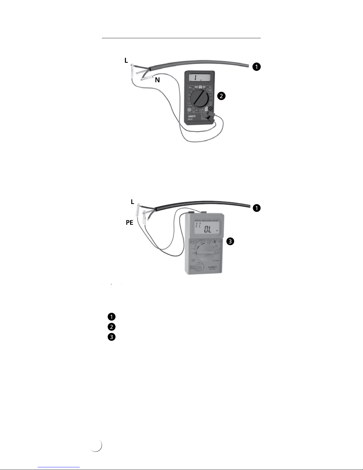
• perform the measurements of:
- heating wire resistance,
- insulation resistance.
The measurement results of the heating
core’s resistance should not vary from the
one given on the label with more than -5%
a n d +10 % .
The insulation’s resistance for the heating
cable, as measured with a tool of the rated
voltage 1000 V (e.g. megaohmmeter), should
not be below 10 MΩ. Enter the results into
the Warranty Card.
When the surface has been nished, repeat
the measurements and compare the results
to ensure that the heating cable has not been
damaged while surface installation works.
17
ELEKTRA
Heating Cables
(brown
or black)
(yellow-green)
Power supply conductors
Ohmmeter
Megaohmmeter
(brown
or black)
(blue)
Heating wire’s resistance measurement
Insulation resistance measurement
18
Stage 3: Temperature and
moisture sensor’s
installation
preparation
• establish the optimal positioning for the tem-
perature and moisture sensor – aplace which
would be especially vulnerable to prolonged
low temperatures and increased moisture
deposition (e.g. in ashade or exposed to
wind operation) – place here the installation
tube of the sensor on the prepared hardened
base,
• feed the protective conduit with the so called
“draw wire” from the installation tube to
the switchboard (after the surface has been
completed, the protective pipe will enable
feeding the temperature and moisture sensor’s wire),
In case of asignicant sensor’s distance from
the switchboard, or bending of the protective
conduit, it is necessary to:
• install an additional sealed electric box “on
the way” to the board, or
• install the protective conduit with atwisted
pair screened control cable, min. 3-pair (e.g.
LIYCY-P 3x2x1,5) – the sensor’s wire with the
control cable is to be connected with aheat
shrink joint.
Note:
The protective conduit should be run
in such away to enable the future exchange
of the temperature and moisture sensor,
if required.
!
19

ELEKTRA
Heating Cables
Stage 5: Temperature and
moisture sensor’s
installation
The temperature and moisture sensor should be
installed in the installation tube after the surface has been completed. Then, the sensor’s wire
should be fed into the protective conduit installed
before the surface has been completed, with the
so called “draw wire”. Under the sensor, the wire
excess should be deposited (min. 30 cm) for the
future sensor replacement, if required.
Ground temperature and moisture sensor ETOG-56T with
installation tube (for soil, concrete agstones, paving
cobbles etc.) can be used for heating control of drive-
ways, trafc routes, etc.
Stage 4: Finishing
surface works
During surface works, level the installation
tube, so that it is positioned 5 mm below the
level of the surface. Due to this, the water will
be deposited on the temperature and moisture
sensor.
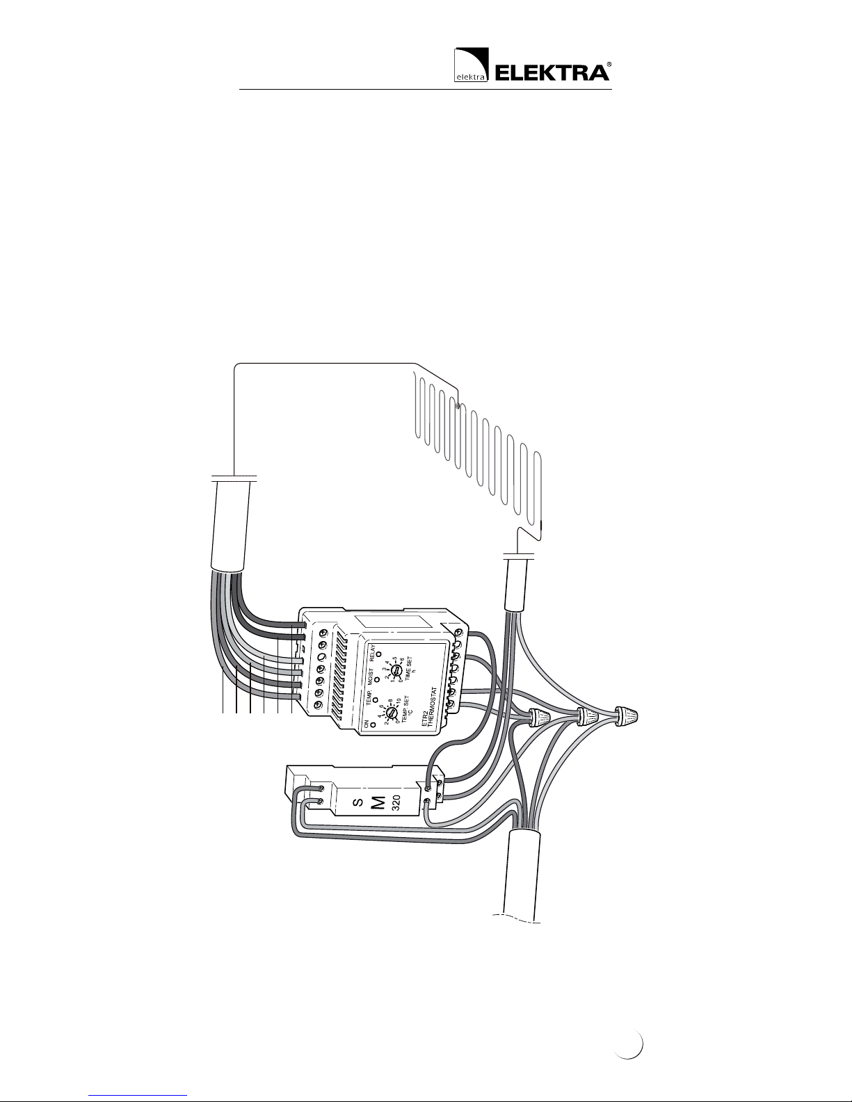
20

Stage 6: Temperature
controller’s installation
The heating cable connection to the domestic
electric circuit should be performed by an authorised electrician.
The connection of the:
1. mains,
2. power supply conductors of the heating cable,
3. temperature sensor,
should be executed according to the diagram
included in the temperature controller’s Instructions.
Example of temperature and moisture sensor’s
installation in the surface
installation tube
protective
conduit
5 mm
sensor’s wire laid with
approx. 30 см excess
sensor
ller
e.g. concrete
surface
compacted base
under the surface
21
ELEKTRA
Heating Cables
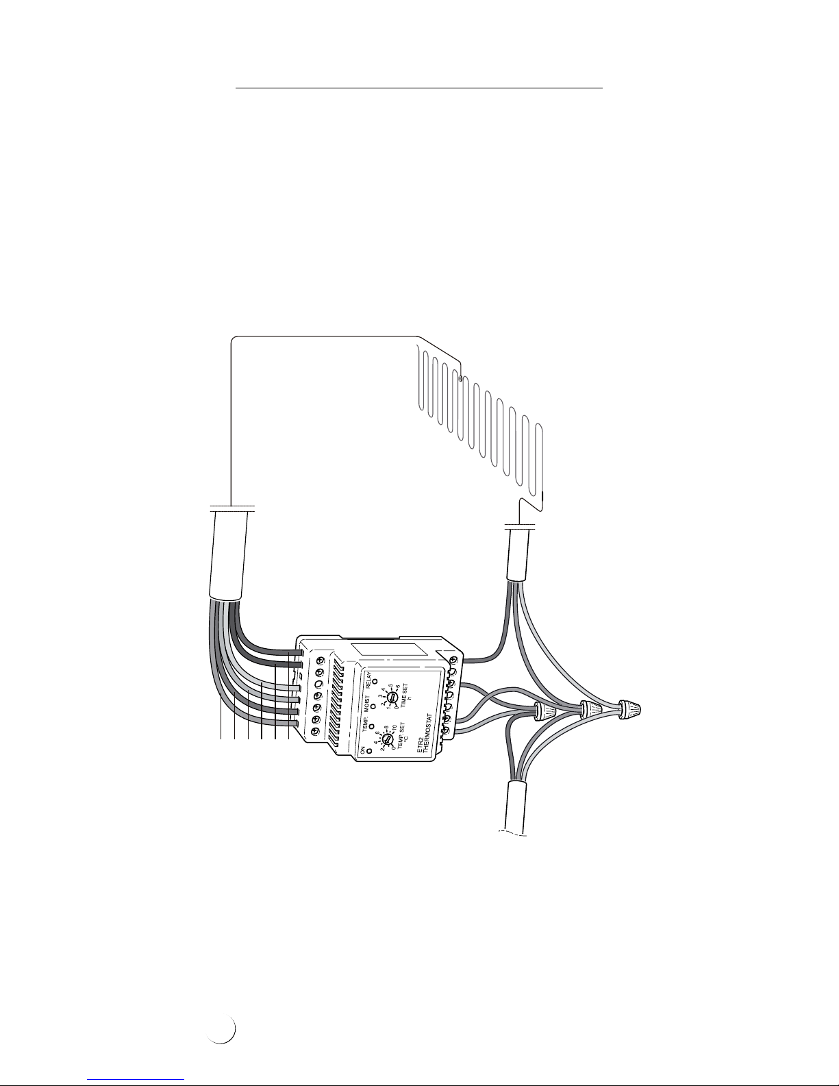
Single-phase electric circuit
Connection diagram of VCD25/230V
heating cable with temperature
and moisture sensor
and ELEKTRA ETR2G controller
ETR2G
230V
sensor cable
heating cable
grey
pink
yellow
white
brown
green
N
NL
PE
L
L
PE
L
N
22
ETR2G
heating cable
grey
pink
yellow
white
brown
green
Three-phase electric circuit
Connection diagram of VCD25/400V
heating cable with temperature
and moisture sensor
and ELEKTRA ETR2G controller
L3
L2
L1
L3
L2
N
NL
PE
L
L
sensor cable
three-phase
circuit
23

ELEKTRA
Heating Cables
Anti-shock protection
The electric circuit of the heating cable should be
equipped with a residual current device of the
sensitivity level ∆ ≤ 30mA.
Warranty
ELEKTRA company grants a 10 year-long
warranty (from the date of purchase) for the
ELEKTRA VCD heating cables.
24
Warranty Conditions
1. Warranty claims requires:
a. that the heating system has been executed
in full accordance with the Installation In-
structions herein, by a certied electrician,
b. presentation of the properly completed
Warranty Card,
c. presentation of the proof of purchase of
the heating cable under complaint.
2. The Warranty loses validity if any attempt at
repair has been undertaken by an unauthorised
installer.
3. The Warranty does not cover the damages in-
icted as a result of:
a. mechanical fault,
b. incompatible power supply,
c. lack of adequate overload and differential
protection measures,
d. discord of the domestic heating circuit
with the current regulations in force.
4. Within the Warranty herein, ELEKTRA com-
pany undertakes to bear exclusively the costs
required to cover the necessary repairs to the
heating cable itself, or to exchange the cable.
5. The Warranty covering the purchased commer-
cial goods does not exclude, limit or suspend
other Buyer’s rights resulting from the incompatibility of the goods purchased with the
agreement of purchase.
Note:
The Warranty claims must be regis tered with the
Warranty Card and proof of purchase, in the place
of purchase or the ofces of ELEKTRA company.
!
25
ELEKTRA
Heating Cables
The Warranty Card must be retained by the Client for the entire warranty
period of 10 years. The Warranty period starts on the date of purchase.
PLACE OF INSTALLATION
Address
Zip code City / town
TO BE COMPLETED BY AN INSTALLER
Name and
surname
Electrical authorisa-
tion certicate n
Address E-mail
Zip code City / town
Phone
n :
Fax
The Warranty claims must be
registered with the Warranty
Card and proof of purchase,
in the place of purchase
or the ofces of ELEKTRA
company.
ō
ō
Heating cable’s core and insulation’s resistance
after laying the heating
cable, before the surface
works commence
Ω
MΩ
after the surface
has been completed
Ω
MΩ
Date
Installer’s signature
Company’s stamp
Note: Heating core’s resistance measurement result should not vary from the label with more than -5%, +10%.
The heating cable’s insulation resistance, as measured with a megaohmmeter of the rated voltage 1000 V, should not
drop below 10 MΩ.
!
Note: The installer is obliged to provide the user with the post-realisation documentation
!
Heating cable’s layout and power supply conduit connection to the switchboard – sketch
 Loading...