

ELEKTRA TuffTec 30, TuffTec 30/400 V Installation Manual
www.elektra.eu
• Tuff Tec™ 30
• Tuff Tec™ 30/400 V
TuffTec™
Instrukcja instalacji
PL
Installation manual
UK
ELEKTRA
Инструкция по монтажу
RU
HEATING CABLES

Applications
ELEKTRA TuffTec™ heating cables are intended
for effective prevention of snow and ice deposition on:
• driveways, roads, footbridges, loading ramps
and parking spaces with asphalt or concrete
surface,
• roofs covered with bituminous materials,
• gutters and downpipes requiring the output of
60 W/m.
Characteristics
ELEKTRA TuffTec™ heating cables feature the
following characteristics:
• high mechanical strength
- cables intended for installations characterised by increased risk of mechanical damages
• high thermal properties
- max. operating temperature: +110°C
- max. exposure temperature (10 min): +240°C
- min. installation temperature: -25°C
• UV-Resistant
• resistance against chemical agents, including
bituminous substances.
3
Heating Cables
ELEKTRA
ELEKTRA TuffTec™ cables are intended for
installation in the conditions of increased risk
of mechanical damages, e.g. in case when
concrete consolidation machinery is utilized for
surface works.
Due to their exceptionally high thermal properties,
as well as resistance against bituminous
substances, the TuffTec™ cables can be safely laid
in asphalt.
Also, the cables can be laid on the roofs with
bituminous coverings.
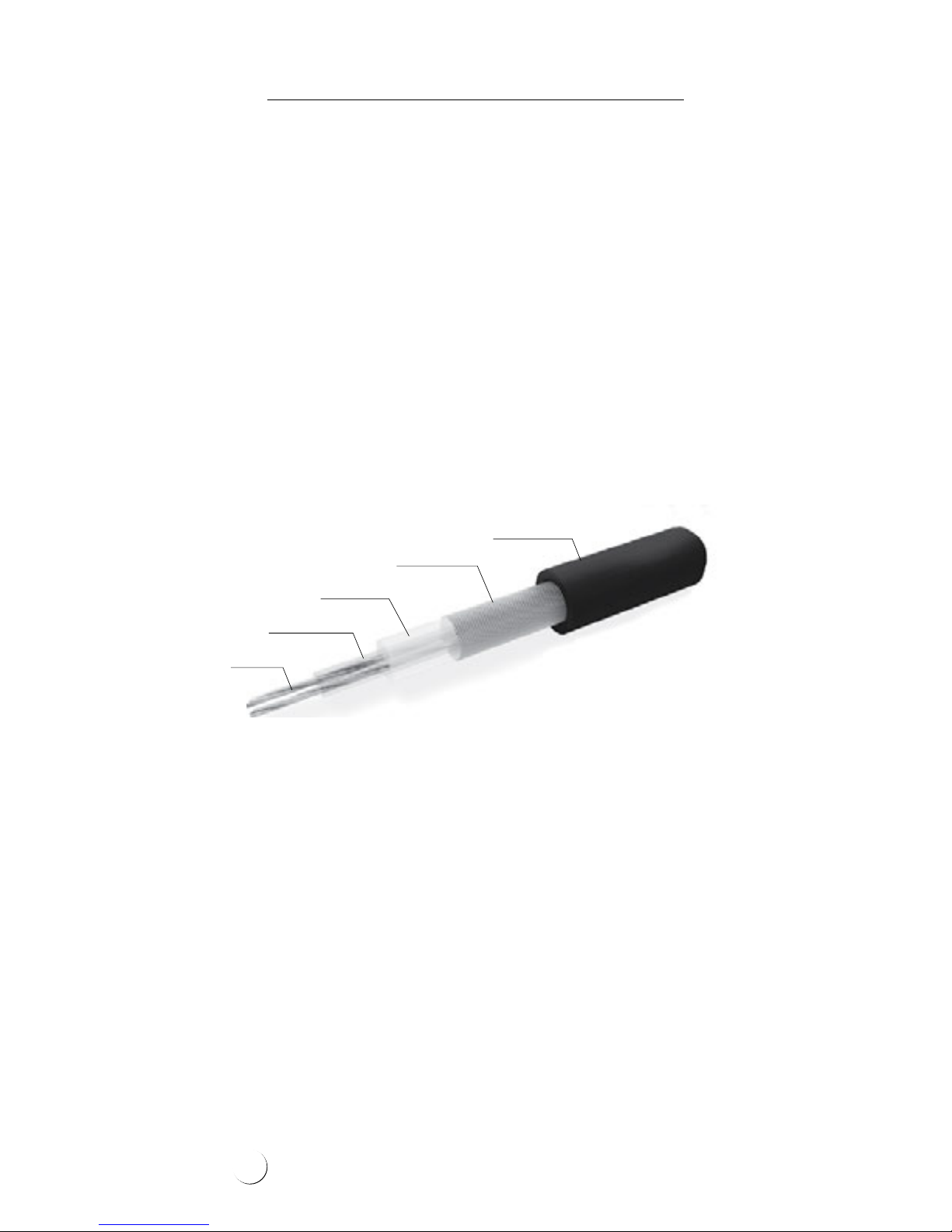
FEP (Teflon)
first insulation layer
Multi-wire
heating core
HDPE second
insulation layer
Tinned
copper braiding
UV resistant
HFFR outer sheath
Construction of the ELEKTRA TuffTec™ heating cable
4
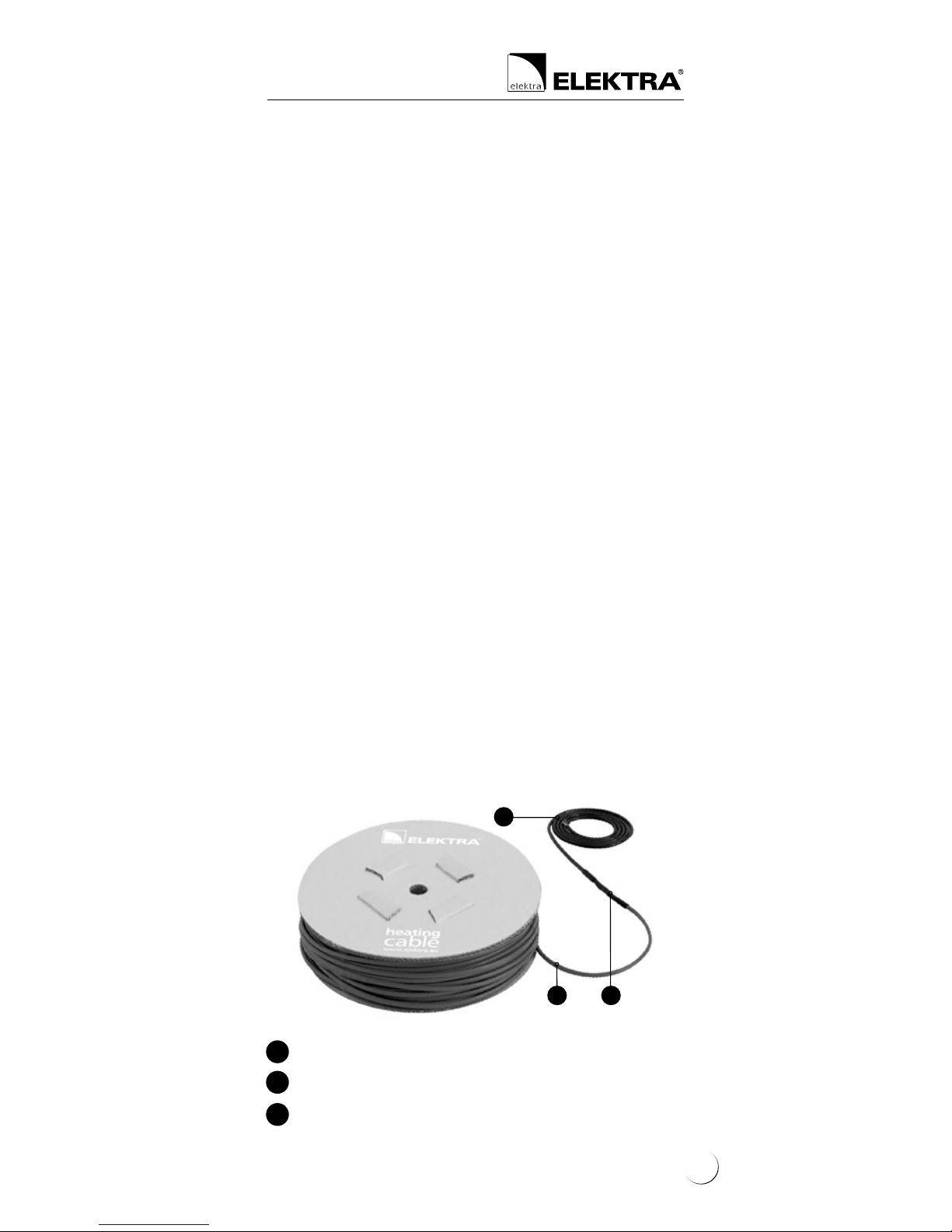
• “cold” power supply conductor
• ELEKTRA TuffTec™ heating cable
• connecting joint between the power supply
conductor and the heating cable
1
2
3
1
2 3
Technical properties
The ELEKTRA TuffTec™ heating cables are produced in ready-made units, manufactured in
compliance with the EN 60335-1 standard.
The ready-made units include heating cables
terminated with a power supply conductor.
Power output 30 W/m
Power supply voltage 230 V, 400 V ~ 50/60 Hz
Cable diameter ~ 6.8 mm
Min. installation temperature -25°C
Max. operating temperature +110 ° C
Max. exposure temperature (10 min.) +24 0 ° C
Power supply conductors 1 x 4 m; 3 x 1.5 mm²
or 3 x 2.5 mm² rubber
insulation and outer
jacket
Heating cables double-core, screened,
single-side powered
Insulation double layer, FEP + HDPE
Outer sheath UV-resistant HFFR
Rated power output tolerance +5%, -10%
Min. cable bending radius 3.5 D
IP rating IPX7
System certication according to ISO 9001
IQNET, PCBC
Markings CE
5
Heating Cables
ELEKTRA
Single-side powered
heating cables
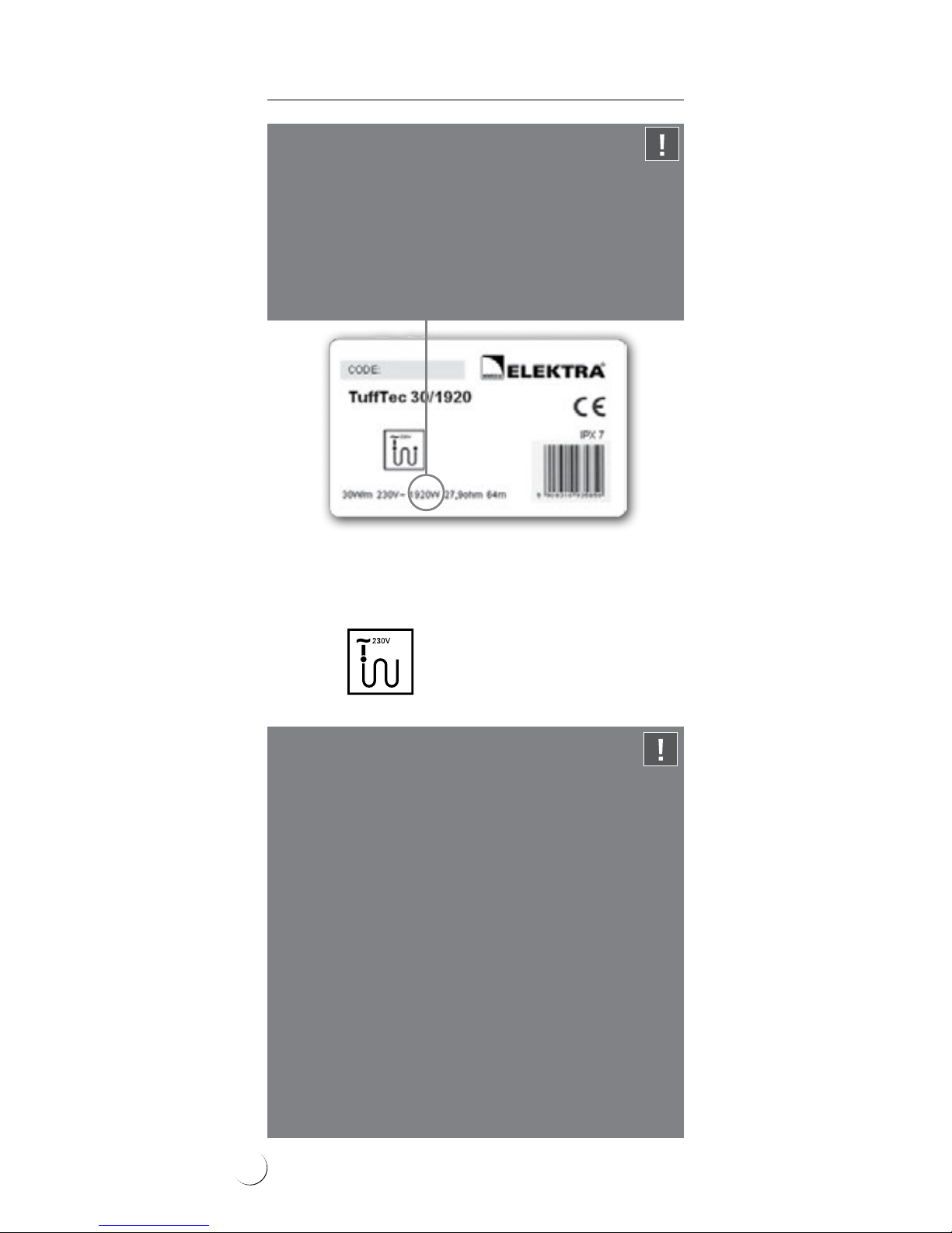
Self-adhesive label
Note:
ELEKTRA TuffTec™ 30 heating cables are designed
for the rated voltage 230 V/50 Hz, and TuffTec™
30/400 heating cables – for the rated voltage
400 V/50 Hz.
Heating cables’ heating output may vary with
+5% and -10% from the nameplate values.
!
The label features the following pictograph:
Note:
Never cut the heating cable.
Never trim the heating cable, only the power
supply conductor may be trimmed if required.
Never squash the “cold tail”.
Do not ever undertake on your own any attempts
to repair the heating cables, and in case any
damage is detected, report the damage to an
ELEKTRA authorized installer.
Never stretch or strain the cable excessively, nor
hit it with sharp tools.
Do not install the heating cables when ambient
temperature drops below -25°C.
!
6
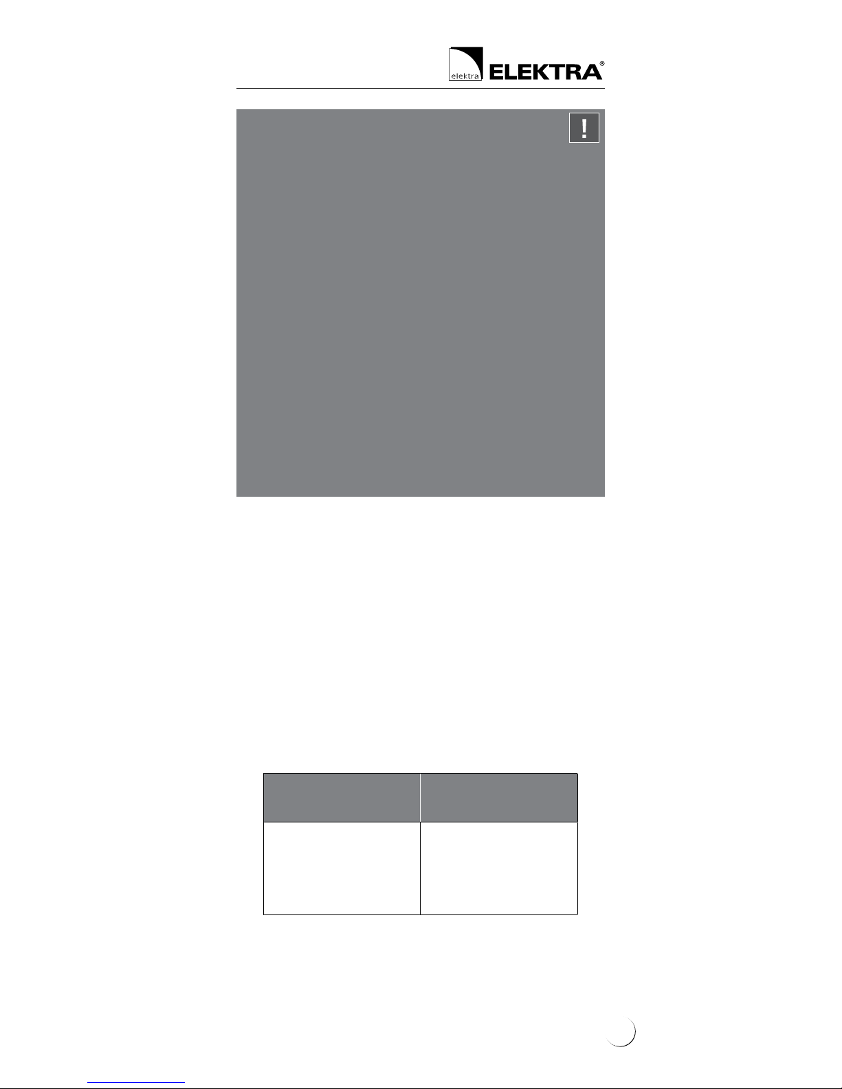
General information
Surface protection against snow
and ice deposition
When protecting external areas from snow and ice
deposition, it is required to assess the required heat
output value per m
2
of the surface. Recommended
heat output depends on the regional climate conditions, i.e. minimum ambient temperature, snowfall
intensity and wind strength.
Higher output is required if the heated area is:
• exposed to wind from below:
- bridges, stairs, loading ramps, overpasses
• located in a regions of intense snowfall
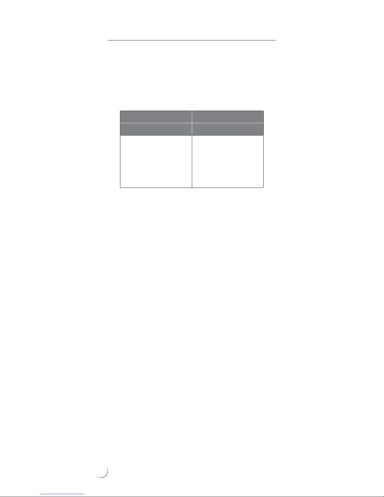
Ambient
temperature
Heat output
[W/ m
2
]
> -5°C
-5°C ÷ -20°C
-20°C ÷ -30°C
< -30°C
200
300
400
500
Note:
Never lead the end joint and the connecting
joint between the heating cable and the power
supply conductor out of the surface. Both joints
must be placed – depending on the type of surface – within the layer of sand, dry concrete or
directly in concrete.
Never bend the joint and end seal.
Heating cables must be installed according to
the Instructions.
Mains connection of the heating cables should
be performed by an authorized electrician.
Power supply conductors (”cold tails”) in asphalt
should be positioned in the protective metal
installation conduit. Alternatively, power supply conductors can be led out of the area where
asphalt will be poured out.
!
7
Heating Cables
ELEKTRA
Applying insulation layer to the surfaces exposed
to wind from below can improve effectiveness.
Depending on the cable spacing, it is possible
to obtain required output per m
2
of the heated
area.
Cable spacing cannot drop below 5 cm.
To protect large areas against snow and ice deposition, one option is application of 400 V voltage
heating cables, which would evenly load the electric circuit. Application of such cables would also
reduce installation works, limiting the required
number of heating cables.
Heat output 30 W/m
[W/m
2
] [cm]
300
375
430
500
600
10
8
7
6
5
Protection of bituminous roofs,
gutters and downpipes against snow
and ice deposition
Thanks to their exceptionally high resistance
against damaging inuence of any bituminous
substances, ELEKTRA TuffTec™ heating cables are
ideally suited for the purposes of heating roofs
covered with tar paper, roof tiles or bituminous
shingles.
Selection of the required heat output depends on
the regional climate conditions of the zone where
the installation is to be positioned.
8

It is recommended to heat gutters and roof edges
adjoining them on the width of approximately 50
cm, as well as roof channels. Effective heating
of these elements will facilitate roof outow of
melted snow, and will prevent icicles.
Tar paper-covered roofs are usually at (up to
15°) and require higher heat output. Especially
roof valleys and channels are exposed to snow
deposition.
Heat output for the moderate climate zone
ELEKTRA TuffTec™ heating cables can be installed
in gutters or downpipes of buildings located
in cold climate zones, where it is also necessary
to execute high heat output, i.e. 60 W/m by
double-laying the cables in gutters.
Application Heat output
[W/ m
2
]
Roof channels 200-300
Roof edges approx. 200
Roof stretches
excessing the building’s facade
approx. 300
9
Heating Cables
ELEKTRA
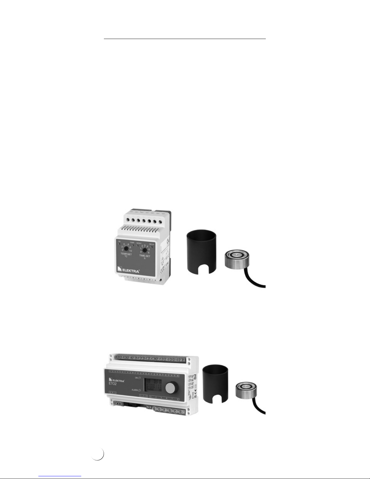
Anti-snow and anti-ice controls
• for the protection of surfaces
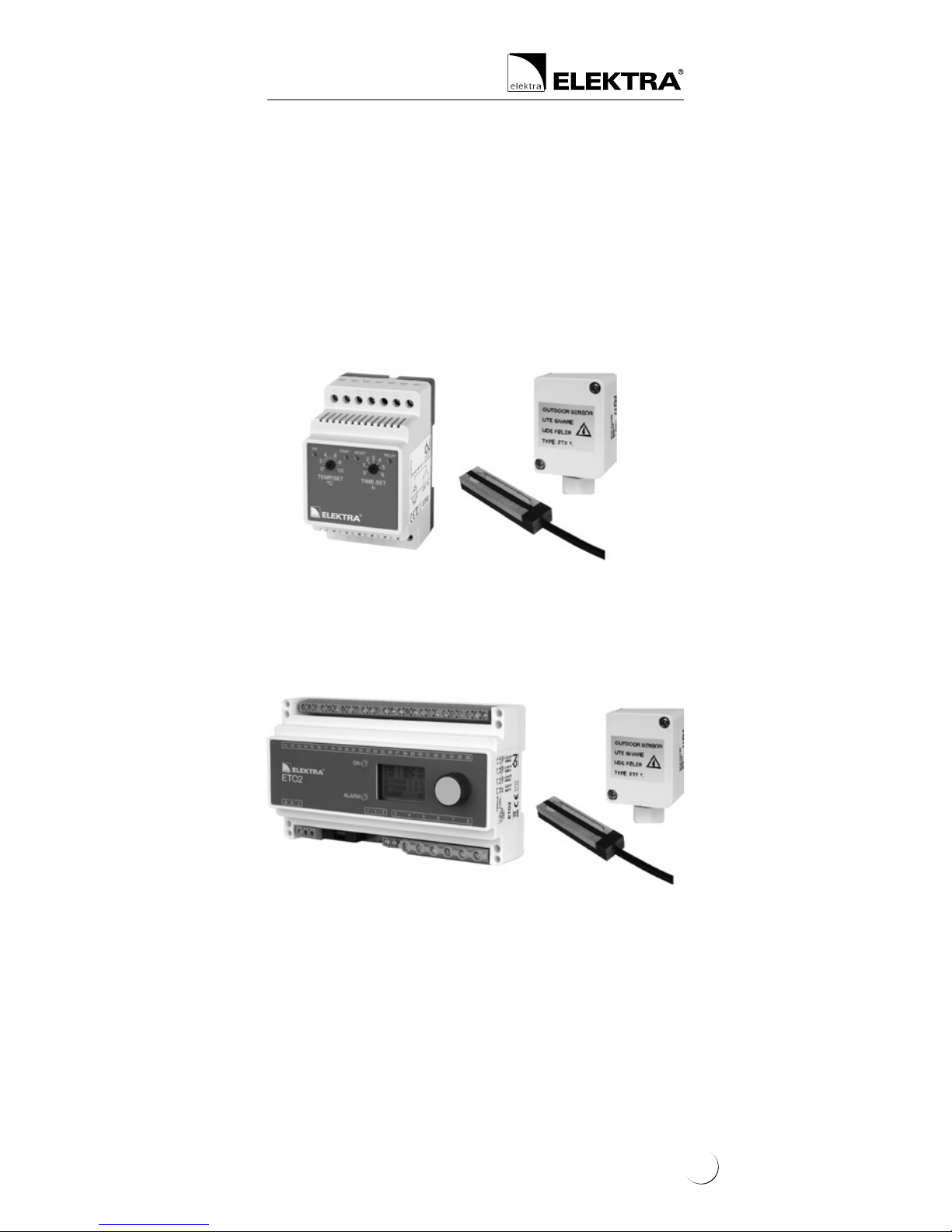
ELEKTRA ETOG2 controller – max. load up to 3x16 A.
For applications in extended heating systems.
ELEKTRA ETR2 controller – max. load up to 16 A,
total output of installed heating cables must not
exceed 3600 W. As standard, equipped with one
temperature and moisture sensor with installation
tube.
Controls
Properly selected control system will ensure adequate operation of the heating system only during
snow and freezing rainfall. A temperature controller with a temperature and moisture sensor will
automatically recognize the weather conditions.
The heating system will be then kept on standby
and only switched on when actually necessary. For
this purpose, DIN-bus installed controllers ELEKTRA
ETR2 and ETO2 can be utilised.
10
• for the protection of roofs,
gutters and downpipes
ELEKTRA ETR2R controller – as standard,
equipped with one air temperature sensor and
moisture sensor.
ELEKTRA ETOR2 controller – as standard, equipped
with one air temperature sensor and moisture sensor. Additional moisture sensor can be connected
to this controller, which will enable protection of
two independent roof areas.
Additionally, it is possible to control two independent areas, e.g. a garage driveway and gutters,
with one controller only.
As standard, equipped with one temperature and
moisture sensor and an installation tube. Additional temperature and moisture sensor can be connected to this controller, which will enable protection of two outdoor areas.
11
Heating Cables
ELEKTRA
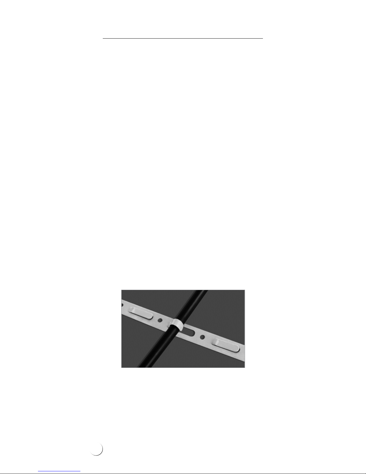
To maintain xed positioning of the cable and
steady spacing conforming to the calculated
values, the cables need to be attached with the
ELEKTRA TMS installation tape (the tape should be
positioned with the distances of 40 cm) or installation mesh of 5 cm x 5 cm grid, made of Ø 2 mm
wire.
The heating cable layout should be commenced
from the side of the power supply conductor,
in such a way to enable easy reach to the switchboard.
If the cold tail needs to be extended, a heat
shrink joint must be used. Ensuring that the connection is safely sealed.
TMS installation tape
Installation
Stage 1: Heating cable’s
installation
1) in the surface
Before commencing the installation of the system, it is required to assess the necessary heat
output per m
2
, as well as calculate the required
spacing of the heating cable.
In order to calculate the required heating cable’s
spacing, apply the following formula:
a-a = S/L
where:
a-a: distances between cables,
S: surface area, for the surface heated with
the heating cable,
L: heating cable’s length.
12
The heating cable layout will depend from
the surface type.
Asphalt surfaces
Stages of works:
• Metal installation tape or mesh is placed on the
compacted (hard core) base, with the heating
cable attached to it – installation tape’s tongues
should be folded so that they would not
straighten up during asphalt rolling
• Power supply conductors (”cold tails”) in
asphalt should be positioned in the protective
metal installation conduit. Alternatively, power
supply conductors can be led out of the area
where asphalt will be poured out
• The 40-50 mm-thick layer of asphalt is laid out
manually – Stage 4
• The asphalt surface is rolled – Stage 4
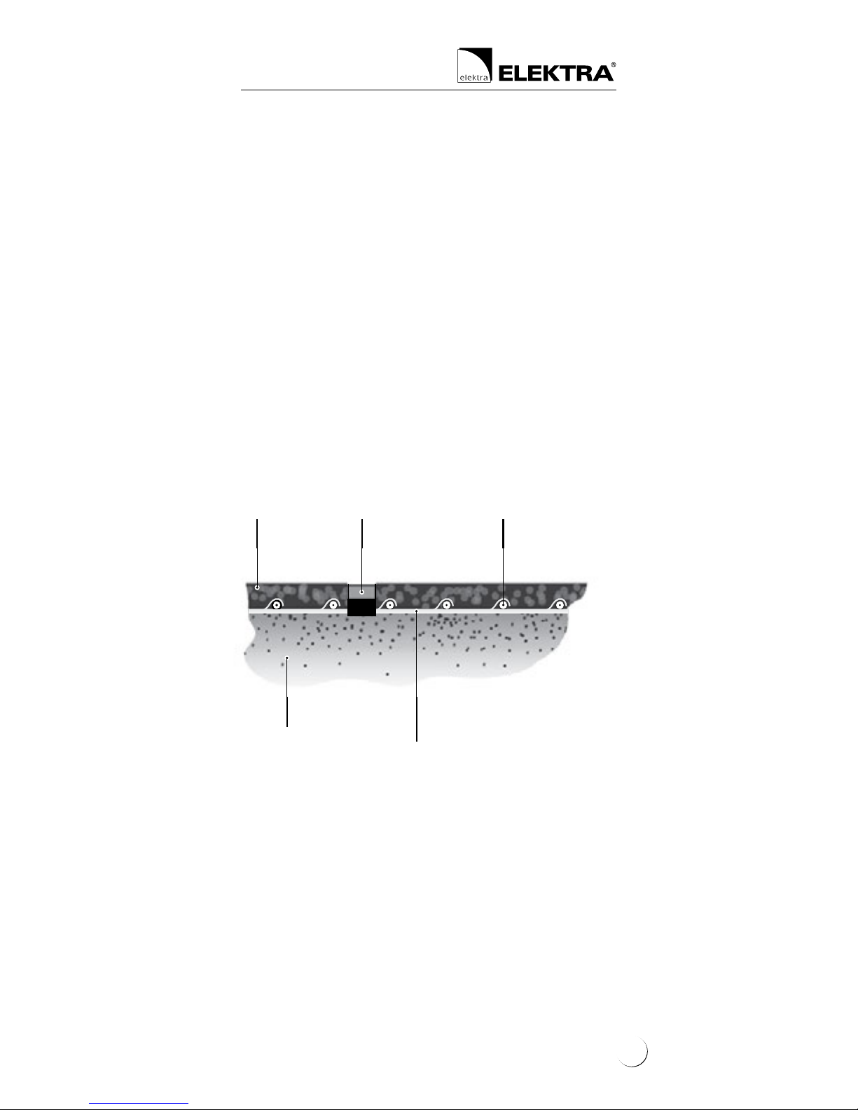
Cross section of a driveway or road with asphalt surface
40-50 mm-thick
layer of asphalt
Temperature
and moisture sensor
in installation tube
Compacted
base
TM
ELEKTRA TuffTec
heating cable
Metal installation mesh
or ELEKTRA TMS
steel installation tape
Concrete surfaces
Concrete surfaces require epansion joints. Unreinforced
concrete slabs should be divided into expanded areas
of the surface no larger than 9 m
2
, reinforced concrete
agstones – into areas no larger than 35 m
2
. The length
of the heating cables should be selected so that they
would not cross the expansion joints. Only the power
supply conduits (“cold tails”) can cross the expansion
joints. They are to be placed in a metal protective conduit of the length of approx. 500 mm.
13

Heating Cables
ELEKTRA
ELEKTRA TuffTec
TM
heating cable
Temperature
and moisture sensor
in installation tube
Expansion joint
Compacted
base
Concrete slab
min. 50 mm thick
Cross section of a pavement or driveway
made of concrete slab
Reinforced concrete agstones
Heating cables can be fastened to the reinforcement of the ferroconcrete agstones. Alternatively, the installation mesh of 100 mm x 100 mm
grid made of Ø 4 mm wire can be applied, which
would facilitate maintaining steady spacing of the
cable, conforming to the calculated values.
ELEKTRA TuffTec
TM
heating cable
Roadway layer
(e.g. resin, quartz)
Reinforcement
of the f
erroconcrete
flagstone
Metal
mesh
Layer of plaster,
e.g. acrylic,
on plastering mesh
Thermal
insulation
Cross section of a suspended loading ramp
Unreinforced concrete surfaces
Stages of works:
• The compacted base is levelled
• ELEKTRA TMS installation tape or installation
mesh are laid on the compacted base, the
heating cable is fastened to them
• The concrete slab works follow – Stage 4
14

Applying thermal insulation layer to ferroconcrete
agstone surfaces exposed to wind operation
from below (ramps, bridges, overpasses) can improve the system’s effectiveness.
2) on roofs covered with tar-paper,
roof tiles or bituminous shingles
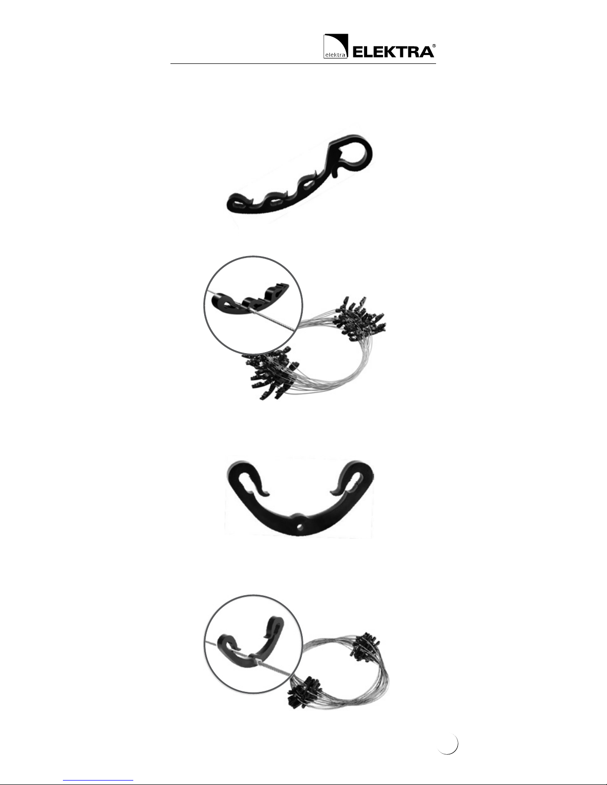
Fastening cables to roofs’ edges
The grips are attached to the roof’s stretches with
pieces of heat-sealing tar paper glued across the
grips.
Titanium-zinc or copper holders
15
Heating Cables
ELEKTRA
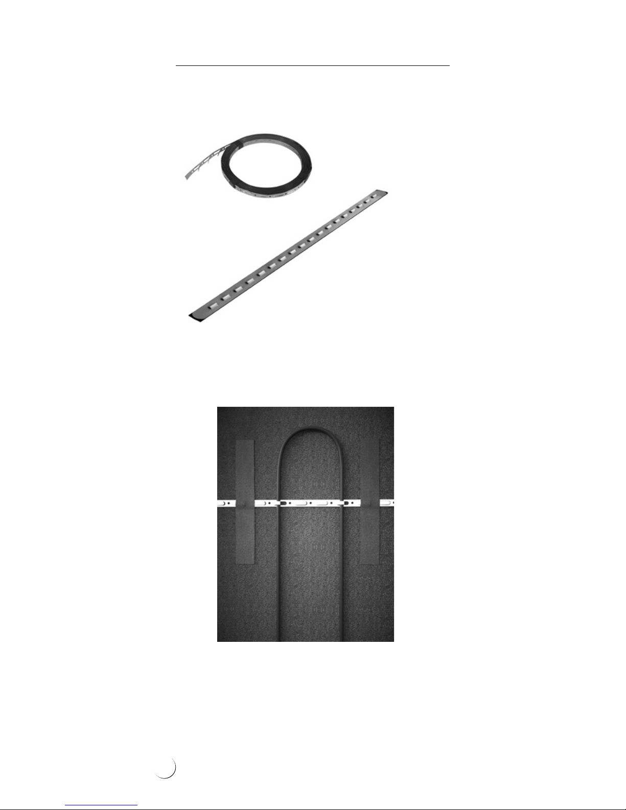
Fastening cables
in roof valleys
ELEKTRA TMS steel installation tape or installation
strips are attached to the roof’s stretches with
pieces of heat-sealing tar paper glued across
the tape or strips.
Downpipes receiving water from roof valleys
require heating:
• internal downpipes at the length of approx. 1 m
• external downpipes at their entire length
ELEKTRA TMS
steel installation tape
Installation strip
16
Gutter holder
Gutter spacing wire
(this method of installation will greatly facilitate cleaning)
Downpipe spacing clip
Downpipe spacing wire
Basic accessories for installation of heating cables
in gutters and downpipes:
17

Heating Cables
ELEKTRA
Stage 2: After the heating
cable has been laid
At this stage, it is necessary to undertake
the following steps:
• Stick into the Warranty Card the self-adhesive
label, positioned on the power supply conductor of the heating cable
• In the Warranty Card, prepare a sketch of the
heating cable’s layout positioning
• Feed the power supply conductor of the he-
ating cable into the switchboard
• Perform the measurements of:
– heating wire resistance
– insulation resistance
The measurement results of the heating
core’s resistance should not vary from the
one given on the label value with more than
- 5 % , +1 0 % .
The heating cable insulation’s resistance,
as measured with an appliance of the rated
voltage 1000 V (megaohmmeter), should not
drop below 50 MΩ. Enter the results into the
Warranty Card.
After the surface has been completed, repeat
the measurements to check whether the
heating cable has not been damaged while
conducting works.
18
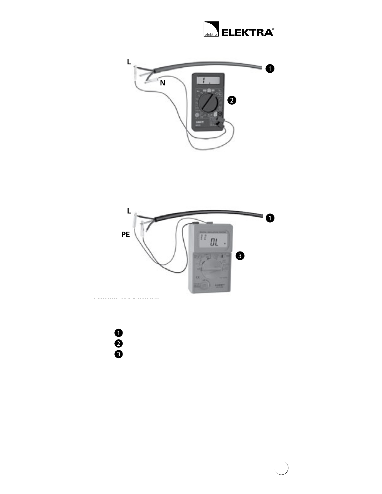
(brown
or black)
(yellow-green)
Power supply conductor
Ohmmeter
Megaohmmeter
(brown
or black)
(blue)
Heating wire’s resistance measurement
Insulation’s resistance measurement
19

Heating Cables
ELEKTRA
Stage 3: Temperature and
moisture sensor’s
installation:
preparation to
in-surface installation
• Establish the optimal positioning for the tem-
perature and moisture sensor – a place which
would be especially vulnerable to prolonged
low temperatures and increased moisture
deposition (e.g. in a shade or exposed to
wind).
• Feed the protective conduit with the so called
“draw wire” from the planned sensor’s positioning to the switchboard (after the surface
has been completed, the protective conduit
will enable feeding the temperature and
moisture sensor’s wire).
Note:
Fill the spot selected for the sensor’s installation with material to be removed after concrete or asphalt has been cured (e.g. a wooden
block of 100 x 100 mm and the height equal to
the planned thickness of the nished surface).
!
Note:
The protective conduit should be run in such
a way to enable the future exchange of the temperature and moisture sensor, if required.
!
20
In case of a signicant sensor’s distance from
the switchboard, or bending of the protective
conduit, it is necessary to:
• install an additional sealed electric box “on
the way” to the board, or
• install the protective conduit with a twisted
pair screened control cable, min. 3-pair (e.g.
LIYCY-P 3x2x1.5)
– the sensor’s wire with the control cable is
to be connected with a heat shrink connecting joint
Stage 4: Finishing surface
works
During execution of the asphalt surface, rst
select the positioning place for the installation
tube, then – after the asphalt has been rolled and
it has cooled down – mount the tube. The space
between the tube and asphalt should be lled
with either concrete or asphalt poured cold, and
the tube should be levelled so that it will be positioned 5 mm below the level of the surface.
For the time of pouring and rolling the asphalt,
the place selected for the positioning of the sen-
sor should be lled with material which – after
the asphalt has cooled down – will be removed
(e.g. a wooden block 10x10x10 cm in size).
Note:
The section of the protective conduit to be laid
in asphalt should be made of a metal pipe, due
to high temperatures present while asphalting.
!
21
Heating Cables
ELEKTRA
Stage 5: Sensor’s installation
1) in-surface temperature
and moisture sensor
The sensor should be installed on the previously
selected and prepared spot. Remove the wooden
block and feed the sensor’s wire with the so
called “draw wire” into the protective conduit
installed before nishing works on the surface.
Under the sensor, the wire excess should be deposited (min. 300 mm) for the future sensor replacement, if required.
The sensor should be positioned approx. 5 mm
below the surface level to enable water deposition on the sensor. After the sensor has been le-
velled, ll the vacant space e.g. with concrete.
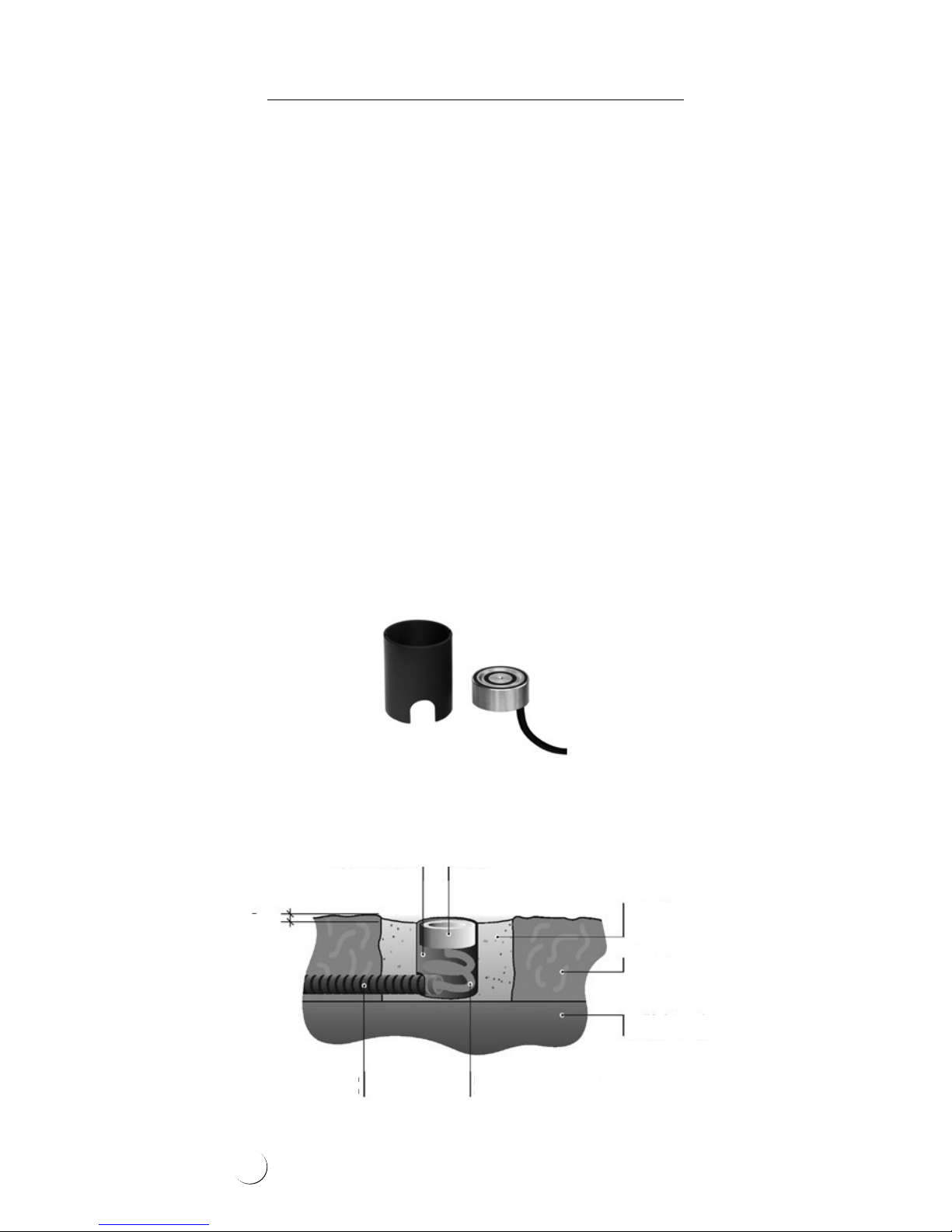
Ground temperature and moisture sensor ETOG-56T with
installation tube (for soil, concrete agstones, paving
cobbles etc.) can be used for heating control of drive-
ways, trafc routes, etc.
Example of temperature and moisture sensor’s installation
in the surface
installation tube
protective
conduit
5 mm
sensor’s wire laid with
approx. 30 см excess
sensor
ller
e.g. concrete
surface
compacted base
under the surface
22
Stage 6: Temperature
controller’s
installation
The heating cable connection to the domestic
electric circuit should be performed by an authorised
electrician.
The in-controller connection of the:
1. mains,
2. power supply conductors (“cold” cables) of
the heating cable,
3. temperature and moisture sensor
should be executed according to the diagram
included in the temperature controller’s Instructions.
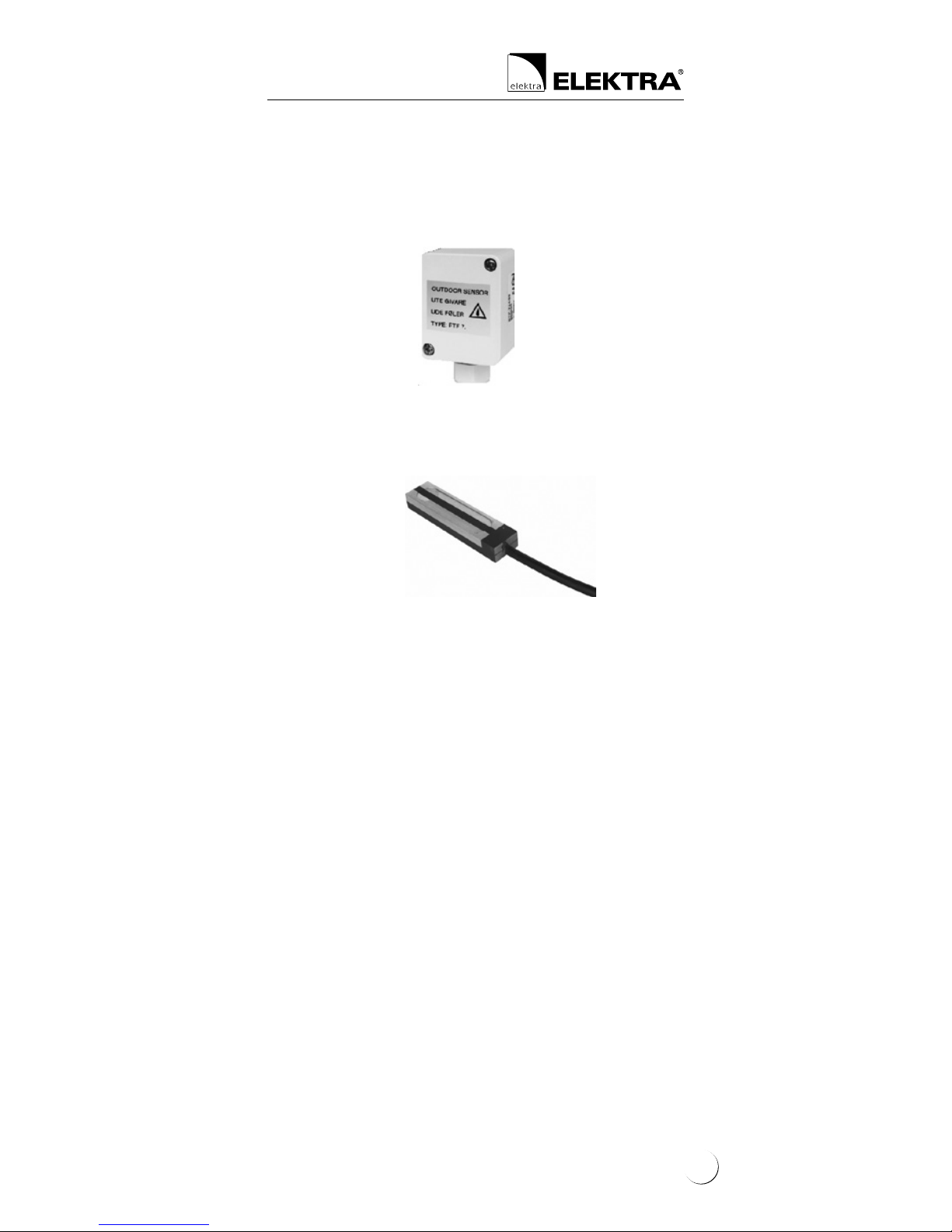
2) on-roof air temperature sensor
and moisture sensor
Position the ETF-744/00 temperature sensor on
the building’s northern wall, in shade.
Position the ETOR-55 moisture sensor between
the cables in the roof’s channel, optimally in the
vicinity of the downpipe.
While selecting the sensors’ positioning,
take into account the necessity of feeding the
wires of both sensors to the controller.
23
Heating Cables
ELEKTRA
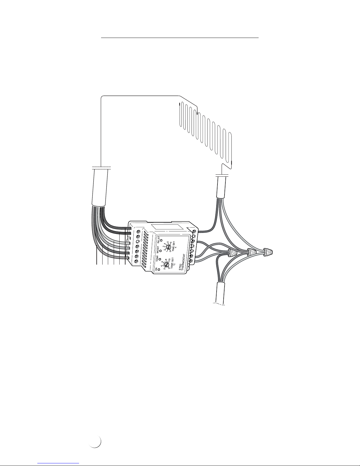
Single-phase electric circuit
Connection diagram of ELEKTRA TuffTec™ 30/230V heating cable
with temperature and moisture sensor
and ELEKTRA ETR2G temperature controller
ETR2G
230V
sensor’s wire
heating cable
grey
pink
yellow
white
brown
green
N
NL
PE
L
L
PE
L
N
24
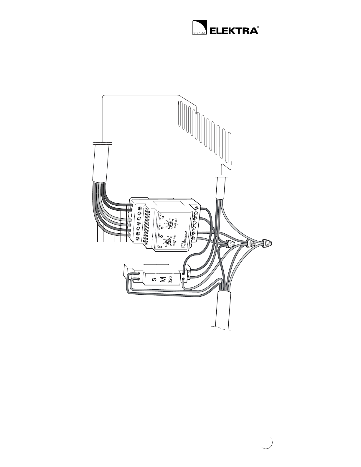
ETR2G
three-phase
electric circuit
heating cable
Three-phase electric circuit
Connection diagram of ELEKTRA TuffTec™ 30/400V heating cable
with temperature and moisture sensor and ELEKTRA ETR2G controller
L3
L2
L1
L3
L2
N
NL
PE
L
L
sensor’s wire
grey
pink
yellow
white
brown
green
25

Heating Cables
ELEKTRA
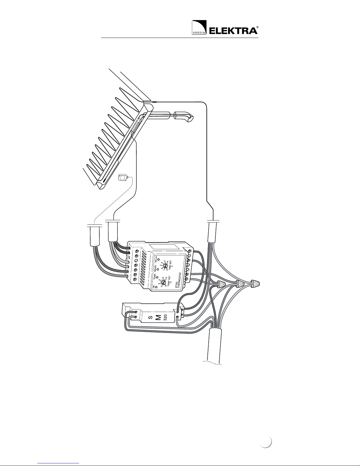
Single-phase electric circuit
Connection diagram of the heating cable
and temperature and moisture sensor
and ELEKTRA ETR2R controller
ETR2R
230V
heating cable
N
NL
PE
L
L
PE
L
N
yellow
white
brown
green
ETOR-55
ETF-744/99
26
ETR2R
Three-phase electric circuit
Connection diagram of the heating cable
and temperature and moisture sensor
and ELEKTRA ETR2R controller
L3
L2
L1
L3
L2
N
NL
PE
L
L
heating cable
ETOR-55
ETF-744/99
three-phase
electric circuit
27

Heating Cables
ELEKTRA
Anti-shock protection
The electric circuit of the heating cable should be
equipped with a residual current device of the
sensitivity level ∆ ≤ 30 mA.
Warranty
ELEKTRA company grants a 10 year-long
warranty (from the date of purchase) for the
ELEKTRA TuffTec™ heating cables.
28

Warranty Conditions
1. Warranty claims requires:
a. that the heating system has been executed
in full accordance with the Installation In-
structions herein, by a certied electrician,
b. presentation of the properly completed War-
ranty Card,
c. presentation of the proof of purchase of the
heating cable under complaint.
2. The Warranty loses validity if any attempt at
repair has been undertaken by an unauthorised
installer.
3. The Warranty does not cover the damages in-
icted as a result of:
a. mechanical fault,
b. incompatible power supply,
c. lack of adequate overload and differential
protection measures,
d. discord of the domestic heating circuit with
the current regulations in force.
4. Within the Warranty herein, ELEKTRA com-
pany undertakes to bear exclusively the costs
required to cover the necessary repairs to the
heating cable itself, or to exchange the cable.
5. The Warranty covering the purchased commer-
cial goods does not exclude, limit or suspend
other Buyer’s rights resulting from the incompatibility of the goods purchased with the
agreement of purchase.
Note:
The Warranty claims must be registered with the
Warranty Card and proof of purchase, in the place
of purchase or the ofces of ELEKTRA company.
!
29
ELEKTRA
Heating cables
The Warranty Card must be retained by the Client for the entire warranty period of 10 years.
The Warranty period starts on the date of purchase
PLACE OF INSTALLATION
Address
Zip code City/town
TO BE COMPLETED BY AN INSTALLER
Name and
surname
Electrical authorisation
certicate №
Address E-mail
Zip code City/town
Phone №
Fax
The Warranty claims must be
registered with the Warranty
Card and proof of purchase,
in the place of purchase
or the ofces of ELEKTRA
company
 Loading...