

Page 1

Zx1i Series
Loudspeaker
Owner’s Manual
Zx1i-90
Zx1i-100
Zx1i-100T
Page 2

Table of Contents
Model Summary .................................................................................... 3
Zx1i-90........................................................................................... 3
Zx1i-100......................................................................................... 3
Zx1i-100T ......................................................................................3
Packing List: Zx1i Install ....................................................................... 3
Product Feature Identification ............................................................. 4
QuickSAM™ (Strong-Arm-Mount™) System ...................................... 4
Step-by-Step Installation and Wiring ................................................... 5
Step 1: Mount the SAM™ Bracket................................................. 5
Step 2: Select Voltage Tap (Zx1i-100T Model Only) ...................... 6
Step 3: Select the Horn Dispersion Orientation ............................. 7
Step 4: Mount the Speaker to the QuickSAM™ Bracket................ 8
Step 5: Wire the Speaker............................................................... 9
Step 6: Secure the Seismic Tab Connection Point ........................ 9
Step 7: Test System Operation ...................................................... 9
Maintenance .................................................................................. 9
Detaching Speaker from QuickSAM™ Bracket................................. 10
Appendix A: Troubleshooting Table ................................................... 10
Appendix B: Painting the Zx1TM Speakers ......................................... 11
Painting Process.......................................................................... 11
Painting the Grille ........................................................................ 11
Appendix C: Technical Specifications ............................................... 11
2 Electro-Voice® Zx1i Owner’s Manual
Page 3
Model Summary
8
y
m
T
:
:
M
g
uded
0
s
n
8
eatheriz
005 1
Exit
T
90
s
gn
g
123 dB Maxim
L
egna
.qer
:- -z
:ycneuqerFssapiH.ceRzH04
ytivitisneSlaixA
1
:)˚09(
:)˚001(
)m1/W1(Bd49
)m1/W1(Bd29
:)˚09(LPSdetaluclaCxa
:)˚001(
Bd321
Bd121
:egarevoClatnoziroH˚001ro˚09
:egarevoClacitreV˚001ro˚05
:rewoPmetsySdetaR.tnoCW002
2
kaePW008,.gorPW004,
:recudsnarTFLrevirD)mm302(ni8,L8VE
:recudsnarTFHtixE)mm4.52(.ni1,5002HD
revirDnoisserp
mo
C
:ycneuqerFrevossorCzHk7.1
:ecnadepmIlanimoNsmhO8
:ecnadepmImuminiMsmhO6
:srotcennoCrotcennoCxineohPniP-4
:lairet
aMerusolcnEremyloPtcapmIhgiH
:noisnepsuSMASkciuQdetargetnI
MT
ytuD-yvaeH
tekcarBgnitnuoMmrA-gnortS
:ellirGAG81,detaoCredwoPretseyloP
leetSdezinavlaG
:)DxWxH(miDmm362xmm282
xmm154
)"53.01x"21.11x"57.71(
t
t
emrofsnarTtuohtiw)sbl5.81(
remrofsnarThtiw)sbl0.32(g
emrofsnarTtuohtiw)sbl5.22(g
remrofsnarThtiw)sbl0.72(g
The Electro-Voice
ZX1i is the new standard of no compromise audio performance
The high-tech enclosure uses injection-molded high-impact polypropylene to make
the ZX1i extremely durable. The enclosure geometry has been engineered to
mounting system. The QuickSAM
is a unique, integrated mounting bracket which is virtually
foolproof. It allows the installer to simply snap the speaker onto the bracket, then
tighten it to the desired position. For array mounting, there is an optional array
t
the higher (vocal) frequencies and the program continues without interruption. Low
frequency current is limited through the transformer eliminating low frequency
the amplifier rating). With the same 50Hz Hi-Pass, 10 speakers on transformers
will have the same full sound as a single speaker at 8 ohms.
x 50
coverage for longer throw and
The ZX1i molded polymer enclosure is inherently water resistant. The addition of a
The ZX1i
sophis-
ticated crossover network integrates it with the DH2005, a 1-inch voice coil true
All three Zx1i models use an 8-inch highexcursion LF driver and a 1-inch exit
titanium compression driver on a
rotatable horn to provide high-fidelity, fullrange sound over a wide coverage area.
The system also features the exclusive
QuickSAMTM mounting system for easy
mounting and aiming.
Zx1i-90
- 90° x 50° Rotatable Horn
- Black or White Models
- Phoenix Input Connector
Zx1i-100
- 100° x 100° Horn
- Black or White Models
- Phoenix Input Connector
Zx1i-100T
- 100° x 100° Horn
- 100W Transformer with 8 ohm
bypass and Automatic Saturation
Compensation (ASC)*
- Black or White Models
- Phoenix Input Connector
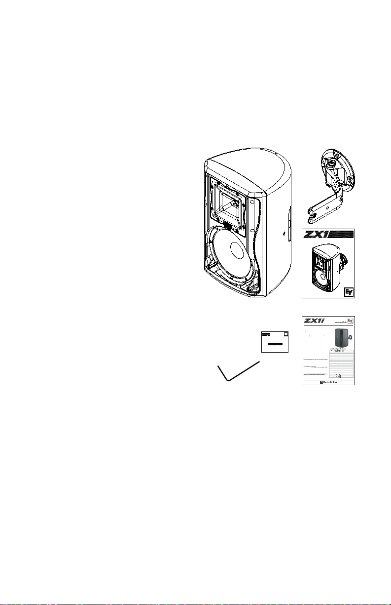
Packing List: Zx1i Install
Listed and illustrated below are the parts
included in each box of the Zx1i speaker.
A 1 Speaker system
B 1 QuickSAM™ assembly
C 1
Owner’s Manual
D 1 Warranty card
E 1 SAM™ mounting tool
F 1 Zx1i Engineering Data Sheet
B
AC
* Automatic Saturation Compensation
(ASCTM) eliminates distortion and
saturation at high volume levels, and an
8 ohm bypass switch adds flexibility.
E
D
F
Figure 1: Zx1i Install Packing List
Electro-Voice® Zx1i Owner’s Manual 3
Key Features
Integrated QuickSA
Bracket Incl
ndoor/Outdoor Design - Meets IEC 529, IP44 & MIL81
Environmental Spec
ASC Automatic Saturation Compensatio
EV8L
ed Cone High-Output LF
DH2
x 50 or 100 x 100 Coverage Pattern
Rotatable Horn Desi
200W Continuous, 800W Peak Power Handlin
General Description
T
Heavy-Duty Strong-Arm Mountin
um SP
ZX1i Series
-Inch
Loudspeaker Syste
. It gently rolls
Page 4
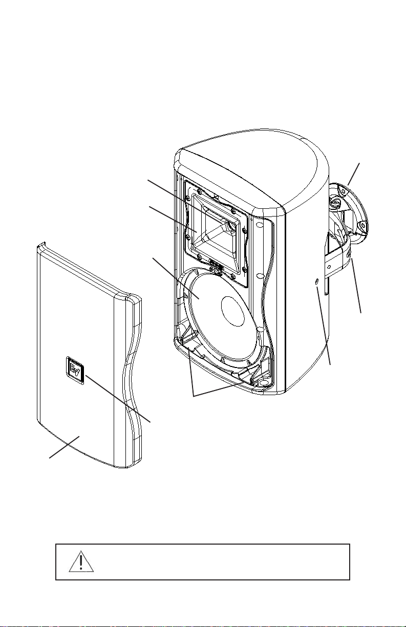
Product Feature Identification
Illustrated below are the major components of the Zx1™ Series full-range speakers.
A. Sweep Adjustment Bolt (Socket Head Bolt “A”)
B. Enclosure Attachment and Rotation Adjustment Bolt (Socket Head Bolt “B”)
C. Dual low-frequency ports
D. Durable zinc-alloy steel grille
E. Cast aluminum Quick Strong-Arm-Mount™ (QuickSAM™)
F. 8” Woofer with weatherized treated cone
G. 1" exit EV compression driver
H. Rotatable Logo
I. Rotatable Waveguide horn
G
I
F
E
A
B
C
H
D
Figure 2: Zx1 Features
QuickSAM™ (Strong-Arm-Mount™) System
Zx1i™s QuickSAM™ system (Strong-Arm-Mount™) excels at meeting the four important
requirements for mounting speaker systems: simple, quick, versatile, and reliable. Three
easy steps and you are done: Securely attach the surface bracket to the wall or ceiling,
click the Zx1i™ enclosure onto the bracket, aim the enclosure and tighten both bolts.
WARNING: Bolt “B” in Figure 2 must be tightened. Failure to
tighten Bolt “B” may allow the speaker to disengage from the
QuickSAMTM Bracket, possibly resulting in serious injury.
4 Electro-Voice® Zx1i Owner’s Manual
Page 5

Step-by-Step Installation and Wiring
Step 1: Mount the SAM™ Bracket to Mounting Surface
WARNING: It is the installer’s responsibility to ensure that the
mounting surface is stable and can support more than the
speaker’s weight!
Use only industry-accepted fasteners and mounting methods when mounting the
bracket. Consult an expert if you are not sure. Read steps 2 and 3 before attaching the
speaker in step 4. For standard vertical installation mount the SAM™ bracket as shown
in Figure 3. For horizontal mounting configurations, mounting the bracket on the bottom
side (as in Figure 4) is easiest, allowing the speaker to be mounted closer to the ceiling.
Figure 3: Vertical Mounting Figure 4: Horizontal Mounting
70°
90°
Figure 5: 70° Rotation Range Figure 6: 90° Sweep Range
Electro-Voice® Zx1i Owner’s Manual 5
Page 6

Step 2: Select Voltage Tap (Zx1i-100T model only)
Before attaching the speaker to the bracket, select the proper voltage tap setting for your
installation. The voltage selector switch is located at the rear of the speaker below the
input terminal panel. The power taps are 100, 50, 25W and 12.5W at both 70.7V and
100V, with a 6W tap for 70.7V only. There is also an 8 ohm bypass setting. The taps are
selected by a rotary switch on the back panel. A guide on the back of each speaker
shows which switch positions to use for the power settings at 70V and 100V. Figure 7
below illustrates the settings.
Voltage Tap
Selector
Voltage Tap
Detail
Figure 7: Volt age Tap Selector (Zx1i-100T Model Only)
6 Electro-Voice® Zx1i Owner’s Manual
Page 7

Step 3: Select the horn dispersion orientation– If necessary
For the 90° x 50° horn version you may elect to rotate the horn assembly for more
effective coverage depending on the orientation of the speaker cabinet in your
installation. The horn is factory-installed with the 90° coverage in the horizontal plane
and the 50° coverage in the vertical plane as shown in Figure 8 below.
To rotate the horn follow the steps below:
1. Remove the logo badge to expose grille mounting screws.
2. Remove the grille assembly – see illustration
3. Remove the screws holding the horn assembly in place. – see illustration
4. Rotate the horn assembly 90°.
5. Secure the horn assembly back to the baffle with the horn mounting screws.
6. Secure the grille assembly to the baffle with grille mounting screws.
7. Secure the logo badge back onto the grille.
90° x 50°
Horn
Horn Mount
Screws
Grille
Enclosure
Assembly
Grille Mount
Logo Badge
Screws
Figure 8: Horn Rotation (90° x 50° Models Only)
Electro-Voice® Zx1i Owner’s Manual 7
Page 8

Step 4: Attach the Speaker to the QuickSAM™ Bracket
After mounting the QuickSAMTM bracket (from Step 1) to the desired surface, attach the
speaker to the QuickSAMTM bracket by inserting the QuickSAMTM into slot on the side of
the speaker until it “clicks” in place. Using the provided mounting tool, tighten the two
socket head bolts A and B enough to allow aiming, as shown in Figure 9. After selecting
the proper horizontal angle, secure the sweep axis as shown by tightening bolt A. Next,
select the proper vertical angle and secure the rotation axis by tightening bolt B. To
tighten the recessed bolt B, insert mounting tool through hole on the side of the speaker.
WARNING: Bolt “B” is what secures the speaker to the
QuickSAMTM Bracket. It is the installer’s responsibility to
ensure that Bolt “B” is fully tightened. Failure to tighten Bolt
“B” may allow the speaker to disengage from the
QuickSAMTM Bracket, possibly resulting in serious injury. Use
of the Seismic restraint is highly recommended. See Step 6.
Socket Head
Bolt A
QuickSAM
TM
Assembly
Mounting Tab
Socket Head Bolt B
(Recessed Inside
Hole)
Enclosure
Figure 9: Att aching S peaker to QuickSAMTM Assembly
8 Electro-Voice® Zx1i Owner’s Manual
Page 9

Step 5: Wire the Speaker
Connect the wires to the speaker using the detachable 4 pole phoenix connector as
illustrated in Figure 10. The 4 connections allow for convenient loop through wiring to
the next speaker system wired in the system.
Step 6: Secure the Seismic Tab Connection Point
The rear of the enclosure includes an eyebolt for connection to a seismic restraint.
Connect it to a properly rated hardware fitting that is securely installed independently of
the SAM™ bracket. Even if your local construction code does not require the installation
of secondary support, its use is highly recommended as additional security.
Seismic
Security Cable
Phoenix
Phoenix
Connector
Connector
and Wires
Polarity Detail
Figure 10: Wiring and Seismic Tab Connections
Step 7: Test System Operation
After all connections are made, test the complete system operation. Appendix A (page
10) contains a troubleshooting table to assist in locating many speaker-related
problems.
Maintenance
Your Zx1™ system has been designed and manufactured to provide years of durability
and reliable service. No routine maintenance is necessary. Units may be cleaned by
wiping with a soft, damp cloth. Never use solvents or harsh cleaning agents of any kind.
Electro-Voice® Zx1i Owner’s Manual 9
Page 10

Detaching the speaker from the QuickSAM™ Bracket
Loosen Bolt “B” (See Figure 9). Press in the Mounting Tab while pulling the speaker
away from the mounting surface. Press in Mounting Tab either with the included
mounting tool (See Figure 11) or by hand (See Figure 12).
Press Here
Figure 11: Detaching Speaker
from QuickSAMTM with tool
Figure 12: Detaching Speaker
from QuickSAMTM by hand
Appendix A: Troubleshooting Table
melborP)s(esuaCelbissoPnoitcA
htllatahtkcehc,dnuosonsierehtfI.stuptuo
pDCamorf,elpmaxerof(reifilpma
.mel
ruoytcatnoc,melbor
ahcus
dnuoSoN.1reifilpmA
-woLrooP.2
ycneuqerF
esnopseR
tuptuotnettimretnI.3
gnilkc
arcsahcus
noitrotsidro
esiontnatsnoC.4
,gnizzubs
gnimmuh,gnissih
gniriW
deriwsrekaepS
ytiralop-fo-tuo
noitcennoCytluaF
reifilpmaevitcefeD
cinortcelerehtoro
ecived
metsysrooP
rognidnuorg
pooldnuorg
I
tcnupelpatsro
pruoyevlostonodsnoitseggusesehtfI
sahleveldnuosehtfI.enil
woleht,)esahp-fo-tuo(
aepsruoynosrecartro
reifilpmaehtdnarotcennoc
borpeht
.rotubirtsidecioV-ortcelErorelaedecioV-ortcelEtseraen
10 Electro-Voice® Zx1i Owner’s Manual
reifilpmaehtotrekaepstsetgnikrownwonkatcennoC
scinortcelee
,evitcasiecruoseht,tcerrocsignituorlangiseht,noera
er/tcerroC.noosdna,pudenrutsiemuloveht
ecalper/riap
.gniriwehtnisimelborpeht,dnuossierehtfI.yrassecensa
otsria
periwtcerrocehtdetcennocevahuoytahtyfireV
ehthguorhtlevelwoltagnihtemosyalP.reifilpmaeht
.)renutroreyal
gninoitcnuflamehthtiwlellarapnirekaepstsetehttcennoC
eht,kaewyrevsiroenog
,hcnip,eparcserevesaylbissop(tinitrohsasahenil
eht,lamronsileveldnuosehtfI.)eru
.)noitcennocdessimaroeriwtucaylbissop(neposieriw
dnaenilehtnwodevom,rekaepstsetehtgnisU
me
lborpehtdnifuoylitnunoitcnuj/noitcennochcaetset
.ytiralopreporpevresbO.titcerrocdna
ytiralopfotuodetcennocerasrekaepsowtnehW
hcaelecnaclliwseicneuqerf
sgnikrameriwehtevresboylluferaC.yllacitsuocarehto
reifilpmaehttahtyfireV.seriwrek
ehtotdetcennocsilanimret)-(
.)01erugiFees(rotcennocxineohpehtfolanimretevitagen
otsrekaepsdnareifilpmatasnoitcennocllakcehC
,stsisrepmelborpehtfI.thgitdnanaelcllaerayehterusne
.evoba1melborPeeS.gniriwroreifilpmaehtniebyamti
silairetammargorpontubtneserpsiesionehtf
.scinortceleehtniniahclangisehtsiesuacylekileht,gniyalp
etalosiotyrassecensatnenopmochcaeetaulavE
.deriuqersa,gnidnuorgmetsysehttcerrocdnakcehC
xineohpehtfolanimretevitisopehtotdetcennocsilanimret)+(
Page 11

Appendix B: Painting the Zx1™ Speakers
Painting Process
The Zx1™ is made of high-impact polystyrene, which accepts a wide variety of paints.
· Remove the grille and mask the baffle.
· Clean the cabinet and grille by rubbing the speaker with a lightly dampened
cloth. Do not, however, use abrasives such as sandpaper or steel wool. Never
use gasoline, kerosene, acetone, MEK, paint thinner, harsh detergents, or
other chemicals, as these agents may cause permanent damage to the
enclosure.
· After cleaning, apply latex or enamel paint. Spraying is recommended
Painting the Grille
Painting the grille requires spray painting. If the grille is rolled or brush painted, the mesh
may become clogged with paint and poor sound quality may result.
Appendix C: Technical Specifications
1
esnopseR.qerF
:)Bd3-(zHk02-zH06
1
egnaR.qerF
1
Half Space Measurement.
2
IEC Pink Noise, 6 dB Crest Factor.
Electro-Voice® Zx1i Owner’s Manual 11
:)Bd01-(zHk02-zH84
:ycneuqerFssapiH.ceRzH04
1
ytivitisneSlaixA
:)°09(
:)°001(
:)°09(LPSdetaluclaCxaM
Bd321
:)°001(
Bd121
:egarevoClatnoziroH°001ro°09
:egarevoClacitreV°001ro°05
:rewoPmetsySdetaR.tnoCW002
:recudsnarTFLrevirD)mm302(ni8,L8VE
:recudsnarTFHtixE)mm4.52(.ni1,5002HD
moC
:ycneuqerFrevossorCzHk7.1
:ecnadepmIlanimoNsmhO8
:ecnadepmImuminiMsmhO6
:spaTegattaWnoisreV"T"ssapybmhO8,
:srotcennoCrotcennoCxineohPniP-4
:lairetaMerusolcnErem
:noisnepsuSMASkciuQdetargetnI
:ellirGAG81,detaoCredwoPretseyloP
:)DxWxH(miDmm362xmm2
:thgieWteNremrofsnarTtuohtiw)sbl5.81(gk4.8
:thgieWgnippihSremrofsnarTtuohtiw)sbl5.22(gk2.01
)m1/W1(Bd49
)m1/W1(Bd29
2
revirDnoisserp
001,05,52,5.21,6-V07
yloPtcapmIhgiH
MT
leetSdezinavlaG
82xmm154
)"53.01x"21.11x"57.71(
kaePW008,.gorPW004,
ssapybmhO8,001,05,52,5.21-V001
ytuD-yvaeH
tekcarBgnitnuoMmrA-gnortS
remrofsnarThtiw)sbl0.32(gk4.01
remrofsnarThtiw)sbl0.72(gk3.21
Page 12

U.S.A. and Canada:
For customer orders, contact the Customer Service department at:
800/392-3497 Fax: 800/955-6831
For warranty repair or service information, contact the Service Repair
Department at:
800/685-2606
For technical assistance, contact Technical Support at:
866/78 AUDIO
Specifications subject to change without notice.
All Locations:
Printed in U.S.A
© Telex Communications, Inc. 7/2005
Part Number 38110-478 Rev A
952-884-4051 Fax: 952-884-0043
www.electrovoice.com
Telex Communications, Inc.
www.telex.com
12 Electro-Voice® Zx1i Owner’s Manual
 Loading...