

Page 1
X-Line Very Compact
XGS-4 Groundstack
User Instructions
XGS-4 Groundstack
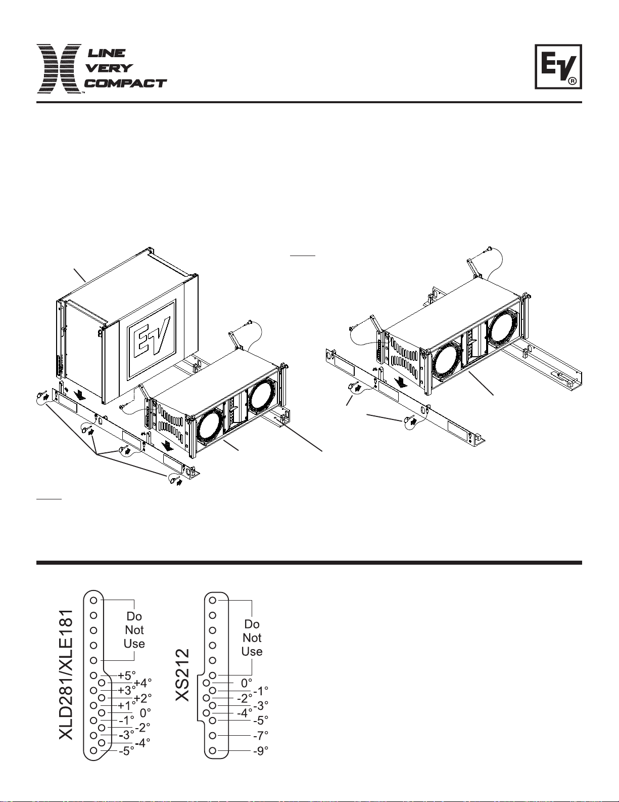
The X-Line Very Comp act Groundstack Rails feature 3 rigging att achment positions to allow for single or dual columns
of X-Line Very Compact Loudspeaker Arrays to be Groundstacked and tilted to obtain the desired sound coverage. The
3 rigging attachment positions allow for 2 options -
1. Stack dual arrays; an XLD281 array at the front position and an XS212 subwoofer array at the rear position.
2. Stack a single array of XLD281’s, XLE181’s, or a combination of XLD281’s and XS212’s at the middle position.
XS212 Loudspeaker
(Rear Position)
Detent Pins
(4 per side)
Note: Dual Array shown using Front and Rear Positions.
Middle Position not used. To switch between Single and
Dual Arrays, Groundstack Rails must be rotated.
XLD281 Loudspeaker
(Front Position)
Note: Single Array shown using
Middle Position. Front and Rear
Positions not used.
Detent Pins
(2 per side)
Lag Bolt Holes
(2 per side)
Figure 1: Attaching Loudspeakers to
XLD281, XLE181, or XS212
Loudspeaker
(Middle Position)
Groundstack Rails
To select the correct pin position on the bottom enclo-
sure of your XLVC Ground Stack, find your enclosure
type and specific angle, and pin the Ground Stack
swing arm to that position. For safety reasons, pin
only to numerically indicated positions. Left sides are
shown, right are mirrored views.
Figure 2: Angle Instruction for Bottom Enclosure
Pin Position
Page 2
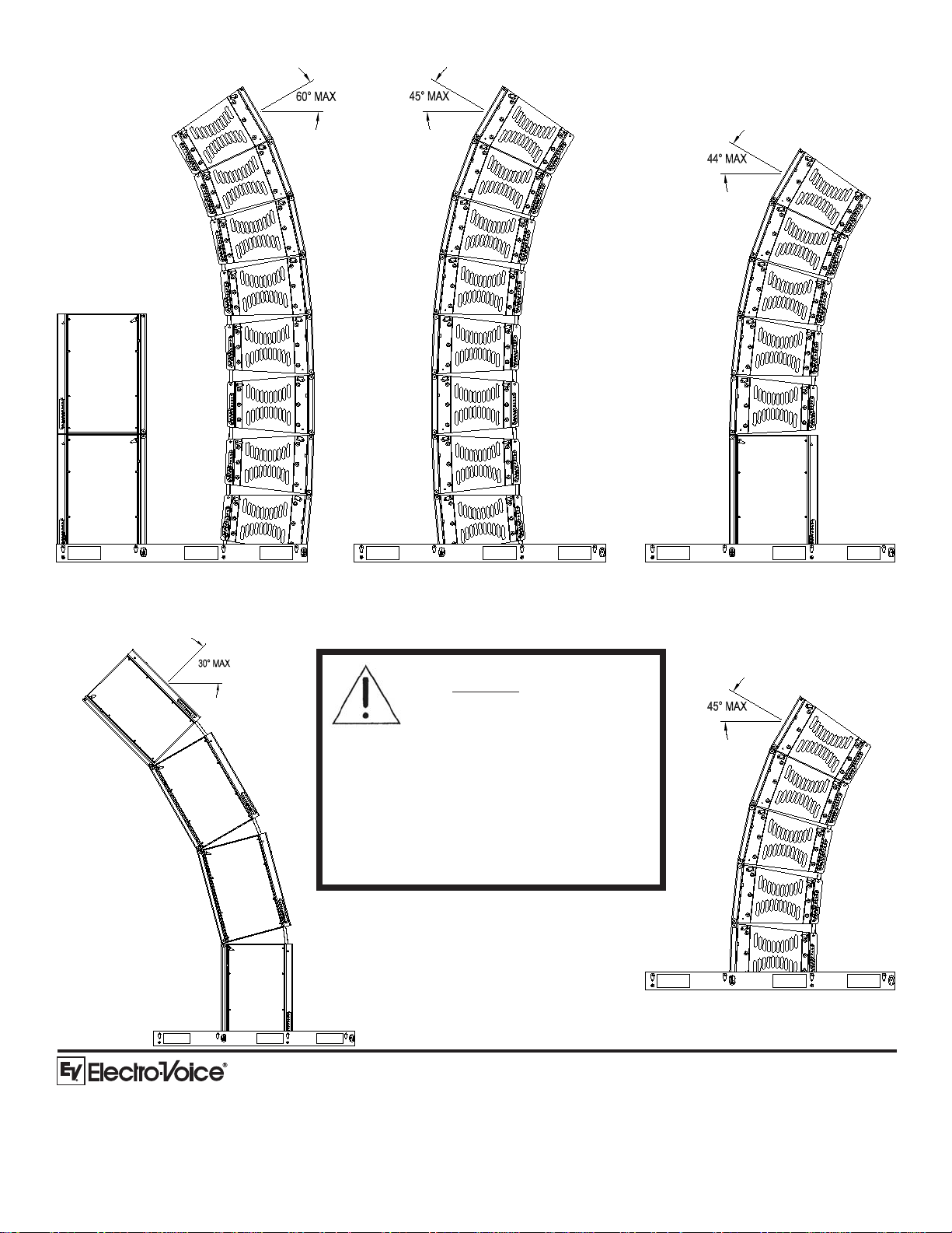
Figure 3: Dual Stack -
XLD281 Array at Front (8 Max)
XS212 Array at Rear (2 Max)
Figure 6: Single Stack -
Figure 4: Single Stack -
XLD281 Array at Middle (8 Max)
These configurations are showing
the maximum number of enclosures and top enclosure angles
allowed. They also show the
proper balance for safety and
acoustical performance. All lesser configura-
tions are allowed at customer’s discretion.
For all configurations approaching these
maximums, and all configurations used
outdoors, use the lag bolt holes in the base of
the L-extrusions to secure the groundstack
base to the mating surface.
XS212 Array at Middle
(4 Max)
Figure 5: Single Stack XLD281 (5 Max) and XS212
(1 Max) Combination Array
at Middle
Figure 7: Single Stack -
XLE181 at Middle (5 Max)
12000 Portland Avenue South, Burnsville, MN 55337
Phone: 952/884-4051, Fax: 952/884-0043
www.electrovoice.com
© Telex Communications, Inc. 11/2005
Part Number 38110-466 Rev A
U.S.A. and Canada only. For customer orders,
contact the Customer Service department at
Europe, Africa and Middle East only. For customer orders,
For warranty information, contact the Service Repair department at:
For technical assistance, contact Technical Support at:
Specifications subject to change without notice.
800/392-3497 Fax: 800/955-6831
contact the Customer Service department at
49 9421-706 0 Fax: 49 9421-706 265
616/695-6831 or 800/685-2606
866/78AUDIO
 Loading...