

Electro-Voice X-Line series, Xvlt, Xfil1, Xsub, Xvls Rigging Manual
...
X-Line Rigging Manual
ELECTRO-VOICE®
X-LineTM Rigging Manual

Table of Contents
Rigging-Safety Warning.............................................................................................................................................. 2
0 Introduction.............................................................................................................................................................. 3
1 X-Line Rigging System ............................................................................................................................................ 4
1.1 Overview of the X-Line Flying System ..................................................................................................... 4
1.2 Enclosure Rigging Hardware Details ....................................................................................................... 6
1.3 Rear Rigging Hinge Details ................................................................................................................... 10
1.4 Front Rigging Strap Details.................................................................................................................... 13
1.5 Xvbp Pull-Up Bar Details ....................................................................................................................... 16
1.6 ATM X-Line Grid Details ........................................................................................................................ 17
1.7 RS-1B Double-Stud Rigging Fitting ....................................................................................................... 18
2 X-Line Rigging and Flying Techniques .................................................................................................................. 19
2.1 Array Considerations ............................................................................................................................. 19
2.2 Adjusting the Vertical Angles of the Enclosures..................................................................................... 19
2.3 Deciding Whether to Use an Xvhg or Xvhl at the Grid ........................................................................... 21
2.4 Rigging an Array with Boxes Using X-Line Dollies ................................................................................ 22
2.5 Pull-Up Techniques ............................................................................................................................... 25
3 Rigging-Strength Ratings, Safety Factors, and Special Safety Considerations ..................................................... 26
3.1 Working-Load Limit (WLL) and Safety Factors ...................................................................................... 26
3.2 Structural Rating Overview .................................................................................................................... 26
3.3 Simplified Structural-Rating Guidelines ................................................................................................. 27
3.4 Complex Structural-Rating Analysis ...................................................................................................... 30
3.5 Wind Loading......................................................................................................................................... 38
3.6 Electro-Voice Structural-Analysis Procedures ....................................................................................... 38
4 Rigging Inspection and Precautions ...................................................................................................................... 39
References ............................................................................................................................................................... 41
Notes ........................................................................................................................................................................ 42
1
ELECTRO-VOICE®
X-LineTM Rigging Manual
Rigging-Safety Warning
The exclamation point within an equilateral triangle is intended to alert
the user to the presence of important operating and maintenance
(servicing) instructions in the literature accompanying the product.
This document details general rigging practices appropriate to the entertainment industry, as they
would apply to the rigging of Electro-Voice X-Line loudspeaker systems. It is intended to
familiarize the reader with standard rigging hardware and techniques for suspending X-Line
loudspeaker systems overhead. Only persons with the knowledge of proper hardware and safe
rigging techniques should attempt to suspend any sound systems overhead. Prior to suspending
any Electro-Voice X-Line loudspeaker systems overhead, it is essential that the user be familiar
with the strength ratings, rigging techniques and special safety considerations outlined in this
manual. The rigging techniques and practices recommended in this manual are, of necessity, in
general terms to accommodate the many variations in loudspeaker arrays and rigging
configurations. As such, the user is expressly responsible for the safety of all specific X-Line
loudspeaker array designs and rigging configurations as implemented in practice.
All the general rigging material contained in this manual is based on the best available
engineering information concerning materials and practices, as commonly recognized in the
United States, and is believed to be accurate at the time of the original printing. As such, the
information may not be directly applicable in other countries. Furthermore, the regulations and
requirements governing rigging hardware and practices may be superseded by local regulations.
It is the responsibility of the user to ensure that any Electro-Voice loudspeaker system is
suspended overhead in accordance with all current federal, state and local regulations.
All specific material concerning the strength ratings, rigging techniques and safety considerations
for the X-Line loudspeaker systems is based on the best available engineering information
concerning the use and limitations of the products. Electro-Voice continually engages in testing,
research and development of its loudspeaker products. As a result, the specifications are subject
to change without notice. It is the responsibility of the user to ensure that any Electro-Voice
loudspeaker system is suspended overhead in accordance with the strength ratings, rigging
techniques and safety considerations given in this document and any manual update notices. All
non-Electro-Voice associated hardware items necessary to rig a complete X-Line loudspeaker
array (grids, chain hoists, building or tower supports and miscellaneous mechanical components)
are the responsibility of others.
Electro-Voice
July, 2002
ELECTRO-VOICE®
X-LineTM Rigging Manual
2

0. Introduction
The X-Line loudspeaker systems represent an important step in line-array technology for largescale sound reinforcement. The individual loudspeaker drivers, acoustic lenses, acoustic
waveguides, enclosures and rigging hardware were all designed specifically for the X-Line
product line to not only achieve the highest acoustic output with the highest fidelity, but also to
produce a precise wavefront from each element to achieve state-of-the-art line-array
performance. A brief description of the product line is included below.
Xvls: Three-way, LF/MB/HF loudspeaker system with a 90°H x 5.0°V coverage pattern. The
system includes two EVX155Plt 15-inch (381-mm) LF drivers, two ND08 8-inch (203-mm) MB
drivers and three ND6-16 3-inch (76-mm) HF drivers. The Xvls utilizes the standard rectangular
X-Line shell with rigging, and may be rigged or stacked right-side-up or upside-down for mirror
image arrays.
Xvlt: Three-way, LF/MB/HF loudspeaker system with a 120°H x 8.5°V coverage pattern. The
system includes two EVX155Plt 15-inch (381-mm) LF drivers, two ND08 8-inch (203-mm) MB
drivers and three ND6-16 3-inch (76-mm) HF drivers. The Xvlt utilizes a trapezoidal enclosure with
rigging that has the same outside dimensions as the rectangular X-Line shell. The enclosure is
trapezoidal in the vertical plane (with a 5.0° total included angle) to minimize space between
boxes with greater vertical splay angles. The Xvlt enclosures may be rigged or stacked right-sideup or upside-down for mirror image arrays.
Xsub: Subwoofer loudspeaker system with two EVX180B 18-inch (457-mm) woofers. The Xsub
utilizes the standard rectangular X-Line shell with rigging, and may be rigged or stacked rightside-up or upside-down for mirror image arrays.
Xfil1 & Xfil2: Three-way, LF/MB/HF downfill loudspeaker systems with a 120°H x 40°V coverage
pattern. The system includes two EVX155 15-inch (381-mm) LF drivers, two ND08 8-inch (203mm) MB drivers and two ND6-16 3-inch (76-mm) HF drivers. The Xfil1 and Xfil2 utilizes a frontslanted enclosure with rigging that has the same outside dimensions as the rectangular X-Line
shell. The enclosure slant allows for maximum downward coverage with a minimum space
between it and the enclosure above. The Xfil systems may not be turned upside down so the Xfil1
and Xfil2 are mirror image systems. The Xfil1 has the HF on the right, while the Xfil2 has the HF
on the left.
3
ELECTRO-VOICE®
X-LineTM Rigging Manual
1. X-Line Rigging System
1.1 Overview of the X-Line Flying System
The X-Line loudspeaker systems have been designed to construct acoustic line arrays. Acoustic
line arrays typically consist of independent columns of loudspeaker systems. Additional columns
are sometimes added to cover different seating sections of a venue. Unlike cluster systems, when
multiple line arrays are used, they are physically separated to minimize the acoustic overlap. This
simplifies the rigging system.
The X-Line loudspeaker enclosures utilize a hinged rigging system that makes constructing arrays
easy, predictable and repeatable. This rigging concept allows arrays to be constructed with
minimal spacing between enclosures. The enclosures are hinged at the back corners using
rigging hardware specially designed for the X-Line system. Adjustable rigging straps are installed
at the front of the enclosure allowing the space between the front corners to be adjusted; hence,
adjusting the relative angle between the enclosures.
A basic array is shown in Figure 1 that illustrates the integral components that make up a typical
X-Line flying system. All of the flying X-Line loudspeaker systems utilize horizontal rigging-track
hardware on the back of the enclosure (at both the top and bottom) and vertical rigging-track
hardware on the front of the enclosures (at both the left and right sides).
Figure 1 illustrates an array column suspended with a grid. Like the loudspeaker systems, the grid
utilizes horizontal rigging-track hardware at the back and vertical rigging-track hardware at the
front like that on the enclosures. The top enclosure is secured to the grid with two quick-release
Xvhg grid hinges at the rear, and two quick-release Xvsg short chain rigging straps at the front.
The grid hinge has only one possible vertical attachment position on both the enclosure and the
grid. The front straps, however, have multiple vertical attachment positions to choose from on the
enclosure and one possible vertical attachment position on the grid. The grid hinges allow the
enclosure to pivot from its top back corner. The vertical angle of the top enclosure, relative to the
grid, is set by the linear position of the front rigging straps in the track on the front of the enclosure
and on the grid.
The second enclosure from the top, shown in Figure 1, is linked to the top enclosure with two
quick-release Xvhl linking hinges at the rear and two quick-release Xvsl long chain rigging straps
at the front. The linking hinges allow the lower enclosure to pivot from the back corner of the top
enclosure. The vertical angle of the bottom enclosure, relative to the top enclosure, is set by the
linear position of the front rigging straps in the track on the front of the top and bottom
enclosures. Additional enclosures may be linked together in the same fashion, as long as the
working-load limits for any of the enclosures, rigging hinges or straps are not exceeded. When
an Xfil1 or Xfil2 downfill is suspended from the bottom of the array, special-length Xvsd downfill
rigging straps are used at the front, while the standard Xvhl linking hinges are used at the rear.
An Xvbp pull-up bar may be attached to the rear rigging of the bottom box to adjust the vertical
tilt angle of the entire array.
ELECTRO-VOICE®
X-LineTM Rigging Manual
4
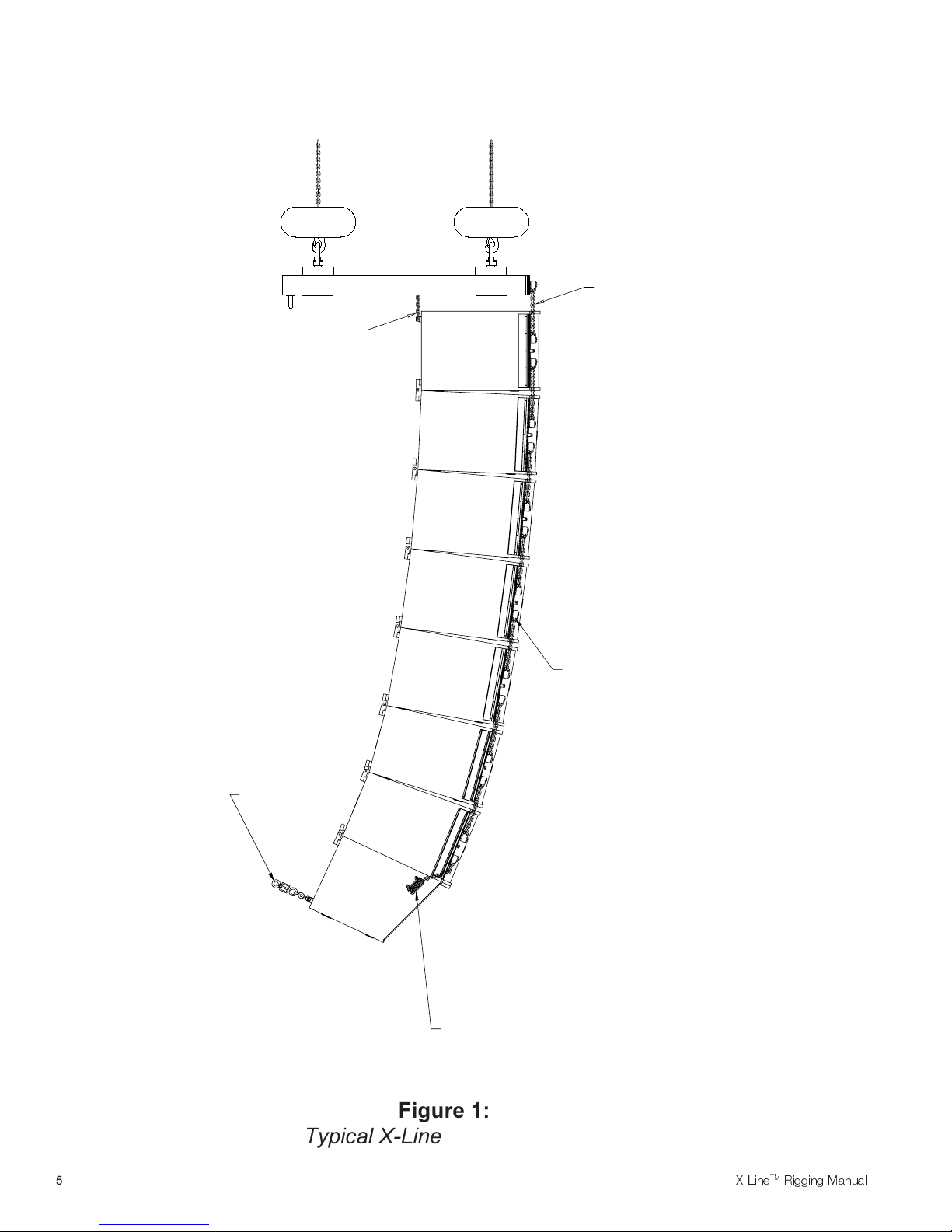
Xvhg or Xvhl
Rigging Hinges
Xvsg
Rigging Strap
Xvsl
Rigging Straps
Optional Xvpb
Pull-Up Bar
Typical X-Line Flying System
5
Xvsd
Rigging Strap
Figure 1:
ELECTRO-VOICE®
X-LineTM Rigging Manual
The grid is suspended by two hoist motors that are attached to two pickup points on the top of the
grid one at the front and one at the back. The two grid pickup points are in line and are
adjustable front to back to help distribute the loads between the hoist motors. For smaller arrays
(8 boxes or less), two one-ton hoist motors are recommended. For larger arrays (more than 8
boxes), two two-ton hoist motors are recommended. Two one-ton hoist motors can be used;
however, the front-to-back distribution of the weight becomes much more critical than with two-ton
hoists.
Note that the weight of an array can be quite substantial and the grid, chain
hoists and building structural supports used to suspend the array must be
capable of supporting such a load with a sufficient safety factor. The reader is
directed to References section of this manual for a list of rigging references (for
background in general rigging practice) and mechanical engineering references
(for background in structural engineering analysis).
1.2 Enclosure Rigging Hardware Details
The X-Line loudspeaker systems have rigging at both the front and rear of the enclosures. The
Xvls, Xvlt and Xsub systems all have the same rigging hardware on both the front and rear of the
enclosures. While the Xfil1 and Xfil2 use the same rigging as the others on the rear of the
enclosures, they use different rigging at the front. Figure 2 shows key dimensions, weights and
centers of gravity for all of the X-Line loudspeaker systems. Figure 3 shows the enclosure rigging
hardware details and key dimensions.
A proprietary high-strength aluminum-alloy track is used at the rear of the enclosures near the top
and bottom for the attachment of two Xvhg rigging hinges, two Xvhl rigging hinges, two Xvhp pickup hinges, or one Xvbp pull-up bar. The track/bracket assembly is extruded as a single piece. One
assembly ties into the back and top of the enclosure, while a second assembly ties into the back
and bottom of the enclosure. Four high-strength, aluminum-alloy bars inside the enclosure tie the
top and bottom track/bracket assemblies together, minimizing the load applied to the enclosure
shell. The cutouts in the rear rigging track are shown in Figure 3a and 3b. The large cutout at the
end of the track is for inserting the rigging hinges. The small holes in the base of the track are for
locking the rigging hinges. The round cutouts are provided so two Electro-Voice RS-1B doublestud swivel-ring fittings may be installed for light-duty lifting applications and for pull-ups. (The
track is also compatible with the New Haven NH32102-2 double-stud fittings.)
At the front of the Xvls, Xvlt and Xsub enclosures is another pair of proprietary high-strength,
aluminum-alloy track/bracket assemblies, which are also extruded as a single piece. One
assembly ties into the left side, top, bottom of the enclosure, while a second assembly ties into the
right side, top and bottom of the enclosure. The front track extends from the top to the bottom on
both sides of the enclosure, eliminating the load applied to the enclosure shell. On both sides of
the enclosure, the front rigging track has six cutouts near the top and bottom, as shown in Figure
3c. The triple-stud fittings on the Xvsg and Xvsl chain rigging straps may be installed at any of the
cutouts. The relative angle between a pair of enclosures (or the top enclosure and the grid) is set
by the position of the front rigging-strap fittings in the track cutouts.
ELECTRO-VOICE®
X-LineTM Rigging Manual
6
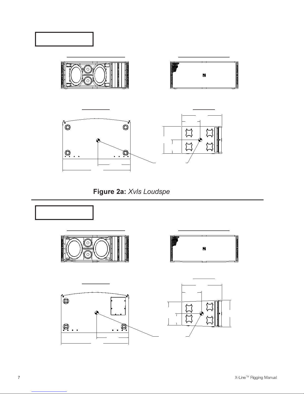
X-Line Xvls 90° x 5°
257 lbs (117 kg)
Front View (Without Grille) Front View (With Grille)
Bottom View Side View
29.15in
(740mm)
13.30in
(338mm)
19.46in
(494mm)
9.73in
(247mm)
X-Line Xvlt 120° x 8.5°
253 lbs (115 kg)
Front View (Without Grille) Front View (With Grille)
Bottom View
Center of Gravity23.40in
49.00in
(1245mm)
(594mm)
Figure 2a: Xvls Loudspeaker System
Side View
29.11in
(739mm)
14.33in
(364mm)
49.00in
(1245mm)
Figure 2b: Xvlt Loudspeaker System
7
23.25in
(591mm)
16.92in
(430mm)
Cent.
8.46in
(215mm)
Center of Gravity
19.46in
(494mm)
ELECTRO-VOICE®
X-LineTM Rigging Manual
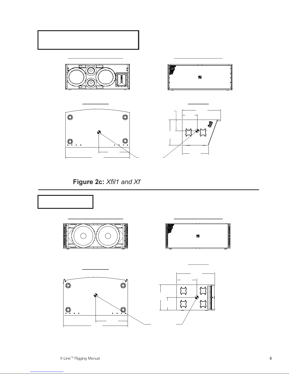
X-Line Xfil1 & Xfil2 120° x 40°
215 lbs (98 kg)
Xfil1 Shown. Xfil2 is Mirror Image of Xfil1.
Front View (Without Grille) Front View (With Grille)
Bottom View Side View
8.43in
(214mm)
19.46in
(494mm)
11.41in
(290mm)
29.15in
(740mm)
Figure 2c: Xfil1 and Xfil2 Loudspeaker Systems
X-Line Xsub
202 lbs (92 kg)
Front View (Without Grille) Front View (With Grille)
49.00in
(1245mm)
Bottom View
25.50in
(648mm)
Center of Gravity
(511mm)
Side View
15.40in
(391mm)
20.10in
29.15in
(740mm)
49.00in
(1245mm)
Figure 2d: Xsub Loudspeaker System
ELECTRO-VOICE®
X-LineTM Rigging Manual
24.50in
(622mm)
19.46in
(494mm)
9.73in
(247mm)
Center of Gravity
8
39.42in
(1001mm)
CENT.
0.10in
(2.5mm)
0.81in
(20.6mm)
TYP.
Figure 3a:
Xvls, Xvlt, Xsub, Xfil1 & Xfil2 Rear Rigging with Xvhl Hinges
39.42in
(1001mm)
CENT.
1.90in
(48.2mm)
TYP.
0.81in
(20.6mm)
TYP.
Figure 3b:
Xvls, Xvlt, Xsub, Xfil1 & Xfil2 Rear Rigging with Xvhg or Xvhp Hinges
47.38in
(1203mm)
CENT.
8.04in
(204mm)
1.00in
(25.4mm)
TYP.
27.50in
(699mm)
TYP.
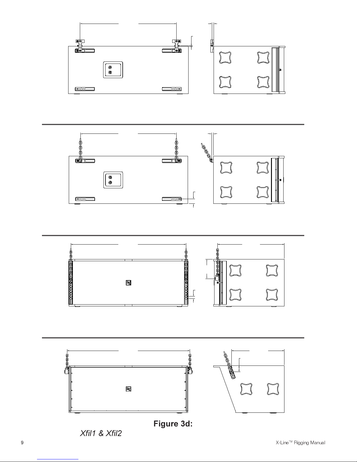
Xvls, Xvlt & Xsub Front Rigging with Xvsg, Xvsl Straps or Xvsf Fittings
Xfil1 & Xfil2 Front Rigging with Xvsd or Xvhp Straps
9
50.50in
(1283mm)
CENT.
Figure 3c:
Figure 3d:
21.80in
(554mm)
2.58in
TYP.
(65.5mm)
TYP.
ELECTRO-VOICE®
X-LineTM Rigging Manual

The Xfil1 and Xfil2 enclosures use a slightly different rigging track arrangement at the front. In this
case, another pair of proprietary high-strength, extruded aluminum-alloy track/bracket assemblies
are mounted on the sides of the enclosure near the front, as shown in Figure 3d. Unlike the other
models, there is only one rigging attachment position on these extrusions.
To facilitate the installation and removal of the linking hinges, alignment feet are installed on the
top and bottom of the X-Line enclosures. Male feet (protruding feet) are located on the bottom of
the enclosures, while female feet (concave dishes) are located on the top. When one enclosure is
stacked or lowered on top of another, the male feet on the bottom of the upper enclosure slide
into the female feet on the top of the lower enclosure, automatically aligning the enclosures. If the
enclosures do not self align, a light side-ways push is all that is needed to make the feet engage
and align. These features allow fast assembly and disassembly of large loudspeaker arrays in
touring applications.
1.3 Rear Rigging Hinge Details
Figure 4 shows the X-Line external rigging hardware details and key dimensions.
Xvhg Grid Hinge: Two Xvhg grid hinges can be used to attach the back of an X-Line enclosure to
the back of an X-Line-compatible grid. Each grid hinge consists of two precision-machined steel
bases connected by an alloy-steel chain, as shown in Figure 4. Each grid-hinge base has a
locking pin that locks the hinge in place horizontally in the track on the grid or X-Line enclosure.
The Xvhg grid rigging hinges need not be installed in the top enclosure and the grid
simultaneously. The length of chain allows the grid hinges to be installed in the grid first. The grid
can then be floated above the top enclosure while the other ends of the grid hinges are installed in
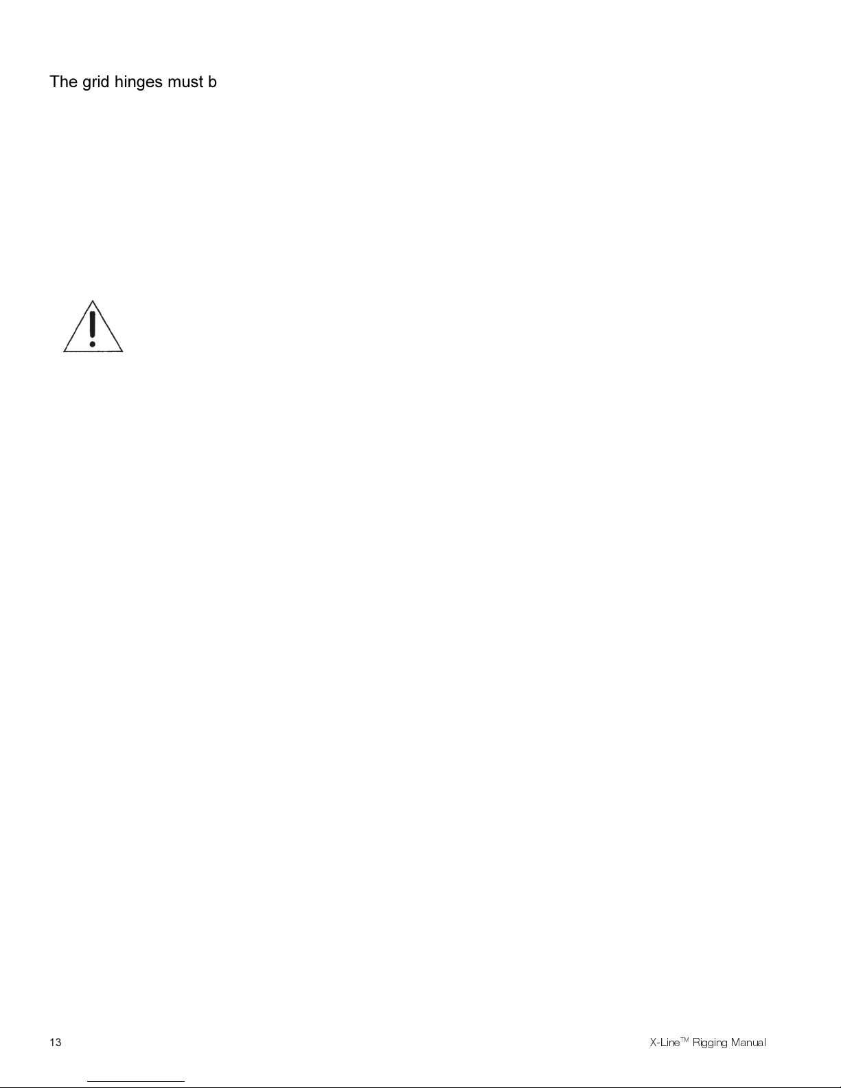
the track at the rear of the enclosures. The grid hinges must be installed with the hinge bases
located at the outside of the track towards the sides of the enclosure as shown in Figure 5 with
the locking pins on the fittings located next to the sides of the enclosure.
To install an Xvhg grid hinge into the track of an enclosure, grasp one of the hinge bases and
firmly insert it into the long cutout in the track, pressing in until the spring-loaded locking pin is fully
retracted. Then apply pressure to slide the hinge base sideways towards the end of the track until
the spring-loaded locking pin drops into the hinge-locking-pin hole in the base of the track. Once
the locking pin is fully engaged, the grid hinge base will be immovable in the track. Use the same
technique for installing the other end of the Xvhg grid hinge in the track at the rear of the grid. The
user must be careful not to insert a twist in the chain when installing the second end. A twist will
result in the grid hinge assembly being shorter and will introduce excessive forces in the chain.
ALWAYS CHECK TO MAKE SURE THAT THE GRID HINGE BASES ARE
INSTALLED IN THE CORRECT ORIENTATION WITH THE HINGES AT THE
OUTSIDE EDGES OF THE TRACK. ALWAYS CHECK TO MAKE SURE THE
GRID-HINGE BASES ARE SECURELY LOCKED INTO THE TRACK, THAT THE
LOCKING PINS ARE FULLY ENGAGED IN THE TRACK AND THAT THERE IS
NOT A TWIST IN THE CHAIN BEFORE LIFTING ANY LOUDSPEAKER
ENCLOSURES OVERHEAD.
ELECTRO-VOICE®
X-LineTM Rigging Manual
10
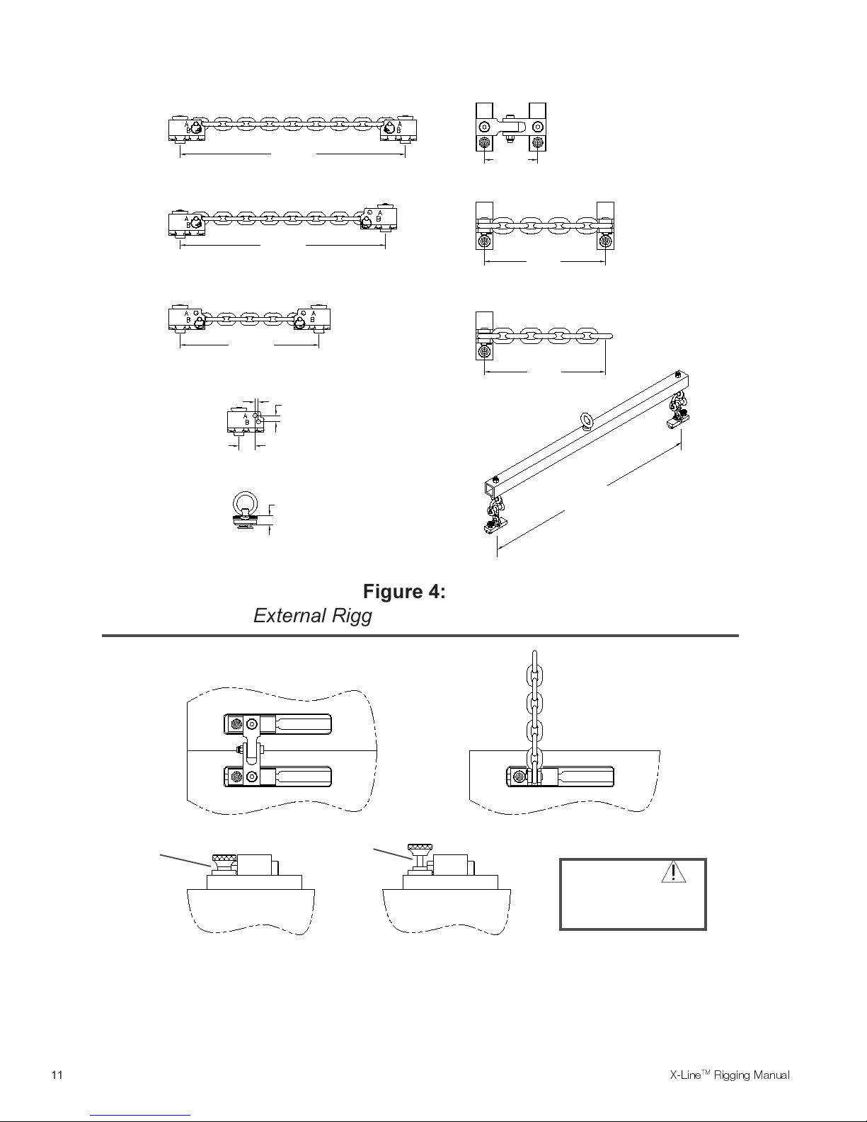
Xvsl Front Linking Strap 2.5lb (1.1kg)
(A-A Configuration Shown)
Xvhl Rear Linking Hinge 3.1lb (1.4kg)
16.375in
(416mm)
Xvsd Front Downfill Strap 2.4lb (1.1kg)
(A-B Configuration Shown)
14.683in
(373mm)
Xvsg Front Grid Strap 2.1lb (1.0kg)
(B-B Configuration Shown)
10.105in
(257mm)
Xvsf Front Fitting 0.9lb (0.4kg)
0.250in (6.4mm)
RS-1B Double-Stud Fitting 0.4lb (0.2kg)
0.445in (11.3mm)
1.152in (29.3mm)
0.875in
(22.2mm)
3.880in
(98.6mm)
Xvhg Rear Grid Hinge 2.7lb (1.2kg)
8.804in
(224mm)
Xvhp Pick-Up Hinge 1.7lb (0.8kg)
8.804in
(224mm)
Xvbp Pull-Up
Bar Assembly
22.9lb (10.4kg)
39.42in
(1001mm)
CORRECT
Figure 4:
External Rigging Hardware Details
Xvhl Linking Hinge
Xvhg Grid Hinges,
Xvhp Pickup Hinges,
or Xvbp Pull-Up Bar
INCORRECT
CAUTION
Hinge Locking Pins Must
be Fully Engaged In Track
Before Lifting Overhead
Rear Rigging Hardware Installation Details
11
Figure 5:
ELECTRO-VOICE®
X-LineTM Rigging Manual

To remove the Xvhg grid hinge, grasp the locking-pin knob and pull out while applying pressure
on the hinge to slide the hinge base toward the long cutout at the end of the track. The hinge base
will come out of the track once it is aligned with the cutout. For added safety, the locking pin has a
special shape that engages with the track to prevent it from vibrating out of the track hole during
use. If the locking-pin knob seems difficult to pull out when removing the hinge, wiggle the hinge
base while pulling out on the knob. When the hinge locking pin is centered in the track hole, the
pin will easily release.
Xvhl Linking Hinge: Two Xvhl linking hinges are used to link a pair of X-Line enclosures
together. In addition, two Xvhl hinges may be used to attach the top cabinet of an array to a grid.
Each linking hinge consists of two precision-machined steel bases connected by a heavy-duty
steel hinge, as shown in Figure 4. The hinge arms pivot, allowing the enclosures to pivot at their
back corners. Each linking-hinge base has a locking pin that locks the hinge in place horizontally
in the rear track of the enclosure.
An Xvhl linking hinge must be installed in the top and bottom enclosures simultaneously. The
linking hinges must be installed with the hinge bases located at the outside of the track towards
the sides of the enclosure as shown in Figure 5 with the locking pins on the fittings located next to
the sides of the enclosure.
To install an Xvhl into the track of a pair of enclosures stacked one on top of the other, grasp both
of the hinge bases and firmly insert both of the hinge bases simultaneously into the long cutouts in
the track of both enclosures, pressing in until both spring-loaded locking pins are fully retracted.
Then apply pressure to slide the hinge bases sideways towards the end of the track until both
spring-loaded locking pins drop into the hinge-locking-pin holes in the base of the track on both
enclosures. Once the locking pins are fully engaged, the linking hinge bases will be immovable in
the track.
ALWAYS CHECK TO MAKE SURE THAT THE LINKING HINGE BASES ARE
INSTALLED IN THE CORRECT ORIENTATION WITH THE HINGES AT THE
OUTSIDE EDGES OF THE TRACK. ALWAYS CHECK TO MAKE SURE THE
LINKING HINGE BASES ARE SECURELY LOCKED INTO THE TRACK, AND
THAT THE LOCKING PINS ARE FULLY ENGAGED IN THE TRACK BEFORE
LIFTING ANY LOUDSPEAKER ENCLOSURES OVERHEAD.
To remove the Xvhl linking hinge, grasp both of the locking-pin knobs and pull out while applying
pressure on the hinge to slide the hinge base toward the long cutout in the track. The hinge base
will come out of the track once it is aligned with the cutout. Like the grid hinge, the locking pin has
a special shape that engages with the track to prevent it from vibrating out of the track hole during
use. If the locking-pin knob seems difficult to pull out when removing the hinge, wiggle the hinge
base while pulling out on the knob. When the hinge locking pin is centered in the track hole, the
pin will easily release.
Xvhp Pick-Up Hinge: Two Xvhp pick-up hinges can be used to attach the back of an X-Line
enclosure directly to a building structure or to a grid assembly that is not compatible with the
X-Line rigging track. Each grid hinge consists of a single precision-machined steel base with an
alloy-steel chain, as shown in Figure 4. The hinge base is identical to that on the Xvhg grid hinge.
Each grid-hinge base has a locking pin that locks the hinge in place horizontally in the track on the
grid or X-Line enclosure. A 3/8-inch shackle can be attached to the end of the chain.
ELECTRO-VOICE®
X-LineTM Rigging Manual
12
The grid hinges must be installed with the hinge bases located at the outside of the track towards
the sides of the enclosure as shown in Figure 5 with the locking pins on the fittings located next to
the sides of the enclosure.
To install an Xvhp pick-up hinge into the track of an enclosure, grasp the hinge base and firmly
insert it into the long cutout in the track, pressing in until the spring-loaded locking pin is fully
retracted. Then apply pressure to slide the hinge base sideways towards the end of the track until
the spring-loaded locking pin drops into the hinge-locking-pin hole in the base of the track. Once
the locking pin is fully engaged, the grid hinge base will be immovable in the track.
ALWAYS CHECK TO MAKE SURE THAT THE PICK-UP HINGE BASES ARE
INSTALLED IN THE CORRECT ORIENTATION WITH THE HINGES AT THE
OUTSIDE EDGES OF THE TRACK. ALWAYS CHECK TO MAKE SURE THE
PICK-UP HINGE BASES ARE SECURELY LOCKED INTO THE TRACK, AND
THAT THE LOCKING PINS ARE FULLY ENGAGED IN THE TRACK BEFORE
LIFTING ANY LOUDSPEAKER ENCLOSURES OVERHEAD.
To remove the Xvhp pick-up hinge, grasp the locking-pin knob and pull out while applying
pressure on the hinge to slide the hinge base toward the long cutout at the end of the track. The
hinge base will come out of the track once it is aligned with the cutout. For added safety, the
locking pin has a special shape that engages with the track to prevent it from vibrating out of the
track hole during use. If the locking-pin knob seems difficult to pull out when removing the hinge,
wiggle the hinge base while pulling out on the knob. When the hinge locking pin is centered in the
track hole, the pin will easily release.
1.4 Front Rigging Strap Details
The Xvsg, Xvsl, and the Xvsd chain rigging strap, shown in Figure 4, are identical except for their
length. Figure 4 shows the X-Line external rigging hardware details and key dimensions.
Xvsg Grid Strap: Two Xvsg grid straps are used to attach the front of the top enclosure to an
X-Line-compatible grid. Each grid strap consists of two rigging fittings connected by an alloy-steel
chain. The Xvsg has the shortest chain of the three front rigging straps to minimize the space
between that the top enclosure and the grid. Each fitting is a proprietary triple-stud fitting that has
a large steel locating plunger. The plunger not only locates in the round cutouts in the track, but
also extends into the base of the track for extra strength.
To install the Xvsg triple-stud fittings in the enclosure rigging track, grasp the fitting with one hand
and pull the spring-loaded safety locking pin out with your free hand. Continue to pull until the
locking pin retracts above the three stud feet of the fitting. Insert the three round feet on the end of
the fitting into the round cutouts in the track and slide the fitting to the desired position. Center the
locking pin of the fitting over one of the track cutouts. Release the locking pin. The pin should
extend beyond the bottom of the fitting and should lock into the round recess in the base of the
track with the locking pin retracting to its normal position. If the pin does not lock into the base of
track, nudge it along the track and wiggle as necessary until it settles into position. When locked,
the fitting will be immoveable in the track. The user must be careful not to insert a twist in the
chain when installing the second end. A twist will result in the grid hinge assembly being shorter
and will introduce excessive forces in the chain.
13
ELECTRO-VOICE®
X-LineTM Rigging Manual
 Loading...