

Page 1
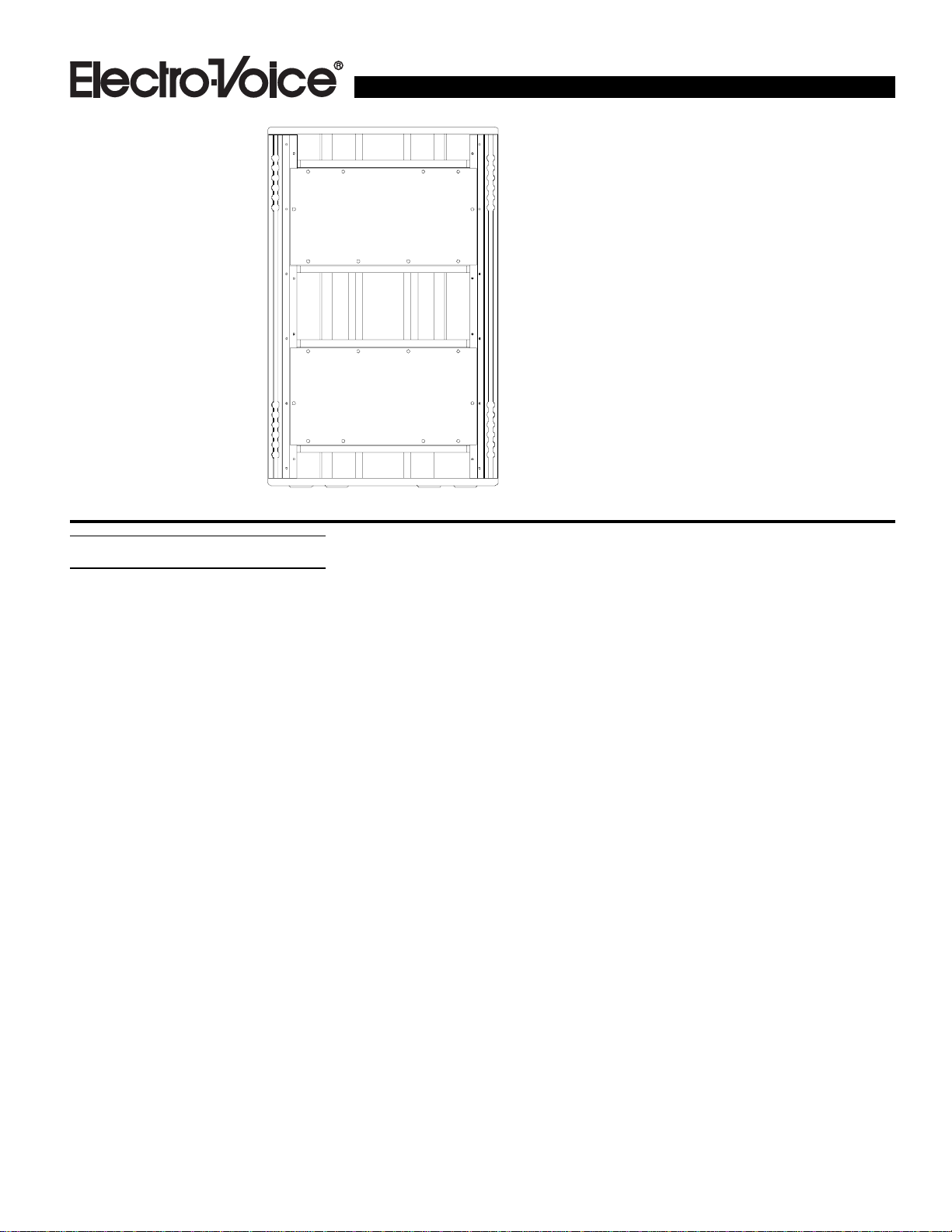
Description
The X-Array
portant advancements in concert-sound reinforcement technology. The design goals
called for the highest acoustic output capability with the highest fidelity in lightweight,
compact enclosures that were easy to array.
The development began with a clean sheet
of paper and took an integrated approach.
The individual loudspeaker drivers, horns,
enclosures, rigging hardware and system
configurations were designed from the
ground up specifically for this high-performance application.
The Xb is a manifolded, vented-box bass
system utilizing two 457-mm (18-in.) woofers. The two woofers face each other in a
manifold chamber at the center of the enclosure. This manifolding technique (U.S.
Patent Number 4,733,749) increases the
acoustic loading, resulting in increased lowfrequency efficiency (at and slightly above
box tuning) and reduced distortion compared
to conventional direct-radiating designs. The
woofers were designed as part of the Xb
development and represent a step forward
in state-of-the-art loudspeaker design in
terms of high acoustic output with low
distortion and low power compression.
Electro-Voice engineers developed a new
technology dubbed Ring-Mode Decoupling
™
product line represents im-
™
(RMD
intelligibility by reducing both linear and
nonlinear resonance modes that color the
sound.
The low-frequency driver in the Xb is the
EVX-180B. An improved version of the industry-standard EVX-180A high-excursion
467-mm (18-in.) woofer that has distinguished itself as an industry standard for
high-power, low-frequency reproduction.
During the X-Array
mal conduction of the motor was improved
and the suspension was redesigned, giving
the EVX-180B even lower power compression and a longer mechanical lifetime. In the
Xb, the woofers are manifolded in a vented
enclosure optimized for maximized output
from 37-160 Hz with minimized distortion.
Ring-Mode Decoupling, (RMD
nique utilized and named by Electro-Voice
to describe a process used to improve sound
quality in loudspeaker systems. RMD offers
a solution to a very fundamental problem. It
has long been recognized that two different
loudspeaker systems can sound different
even though they both may be equalized to
have the same frequency response. This difference is due to a variety of resonances, or
ring modes that color the sound. Although
this ringing may be very low in level compared to the program material, it is still audible. The source of these resonances may
) to substantially improve clarity and
™
development, the ther-
™
), is a tech-
Xb
X-Array™ Bass System
• Unprecedented acoustic output in
a small, lightweight package
• Ring-Mode Decoupling (RMD)™
provides accurate transient detail
• EVX-180B woofers
• Unique rear-hinge rigging
• Enclosure shell and rigging
identical to all of the full-size
X-Array™ systems
be mechanical or acoustical in nature, or a
combination of both. In addition, they may
be linear or nonlinear, resulting in their character changing with level. Furthermore, these
ring-modes may be aggravated when multiple loudspeaker enclosures are assembled
into arrays. The result is a coloration that decreases intelligibility and clarity, with the
nature of that coloration varying with level.
Often, the listener perceives that coloration
as imbalance in the frequency response, and
will attempt to electronically adjust the system to restore the spectral balance. However
this electronic equalization has the negative
effect of changing the program material
itself.
Ring-Mode Decoupling (RMD
mechanical resonances with mechanical
solutions, and acoustical resonances with
acoustical solutions. In the Xb development,
RMD was applied at every level – to the individual LF drivers, the LF enclosure chambers and the interaction between multiple enclosures. The design process included, for
example, the driver cone, suspension geometry and materials, enclosure geometry and
materials, absorptive materials, etc. The result is a dramatic improvement in clarity and
with a much more neutral sound (a lack of
coloration) with the loudspeaker system
maintaining its sonic integrity from the verylowest sound pressure levels to the very-
™
) addresses
Page 2

Xb Bass System
highest sound pressure levels. This means
that the front-of-house engineer will not have
to retune the EQ and level settings as the
SPL is increased throughout the show. This
also means that the sound-system performance will remain consistent in different
array configurations and from venue to
venue.
The X-Array
ging system. A hinge assembly is used to link
Xb Bass System
cabinets together at their rear corners, while
™
systems utilizes a unique rig-
wire-rope/fitting assemblies are used at the
front to adjust the relative angle between systems. (See the Flying the X-Array
™
section for more details.)
The durable Xb enclosure is constructed of
18-mm, 13-ply birch plywood and has a
wear-resistant black, textured paint finish.
The system is trapezoidal, forming an 18°
wedge and includes a heavy-duty steel grille
with a water-resistant charcoal-gray foam interlining. The enclosure features vinyl
bumper pads on the front corners to and feet
on the bottom to resist wear.
A variety of accessories are available for the
X-Array
™
loudspeaker systems, including
rigging hardware, dollies, covers, electronic
crossovers, amplifier racks and speaker cabling. Consult the X-Array
™
Accessories sec-
tion for a complete listing of the available
accessories
Applications
The X-Array
™
loudspeaker systems were designed for optimal performance in both concert-sound and permanent-installation applications where studio-monitor sound quality
is required at concert-sound levels. The
X-Array
™
loudspeaker systems work well
individually, in small arrays and in lar ge arrays. The high acoustic output from these
compact, lightweight systems provide the
highest acoustic-power-to-weight ratio, the
highest acoustic-power-to-frontal-area ratio,
and the highest acoustic-power-to-bulk-volume ratio in the industry. That means that
X-Array
™
systems will be considerably
smaller and lighter compared to competitive
systems having equivalent acoustic output.
With its response from 37-160 Hz, the Xb
is recommended for low-frequency applications where very-high levels of bass are
required from a compact enclosure. Spe-
Systems
cifically, the Xb has been optimized to provide low-frequency reinforcement for the
mid-bass-/high-frequency X-Array
™
systems (like the Xf or Xcn) and the MB/HF
or LF/MB/HF X-Array
™
systems (like the
Xn). The Xb may be used individually or
in multiples to construct low-frequency arrays, or may be used with the mid-bass-/
high-frequency or low-/mid-bass-/high-frequency X-Array
™
loudspeaker systems to
construct large full-range arrays. The Xb
enclosure shell and rigging are identical to
the other full-size X-Array
™
systems for
easy array integration. The Xb would be
well suited for front-of-house, front-fill,
side-fill applications and down-fill applications.
The Xb is intended to be used with other
X-Array
™
systems for a full-range response
as an active system that requires an active
electronic crossover. Both the Electro-Voice
Dx38 and Klark Teknik DN8000 digital
crossovers are recommended for signal
control. (See the Crossover, Equalization
and Signal Delay Controller section.) The
Electro-Voice P3000 amplifier is recommended for powering the Xb. (See the
Amplifier Recommendations section.)
Power-Handling Capabilities
The Xb systems are rated as per the
“ANSI/EIA RS-426-A Loudspeaker PowerRating, Full-Range Test,” which uses a
shaped-random-noise signal to simulate typical music to test the mechanical and thermal
capabilities of the loudspeakers. A digital
crossover was used to provide the appropriate filtering and equalization. The test parameters are as follows:
Low-Frequency Section (Pins 1 and 2 paralleled):
P
: 1,200 watts
E(MAX)
Test Voltage: 58.7-volts rms
117.4-volts peak
RSR (1.15RE): 2.88 ohms
Amplifier Recommendations
Power amplifiers with the following ratings
are recommended for use with the Xb loudspeaker systems:
LF: 800 watts per channel
into 8 ohms
93-volts rms short term
132-volts peak
Xb loudspeakers may be paralleled with
other Xb systems as long as the amplifiers
can drive the lower impedances. To maintain a sufficient damping factor with long
cable runs, amplifier loads of four ohms
per channel are recommended. The
Electro-V oice P3000 amplifiers are ideal for
powering the X-Array
™
systems.
Crossover, Equalization and Signal
Delay Controller
The Xb is intended to be used with other
™
X-Array
loudspeaker systems (like the Xf
or Xn, for example) to construct full-range
arrays as an active system requiring an active crossover, equalization and signal delay
controller. For basic applications, the
Electro-Voice Dx38 2-in/4-out controller is
recommended. For more sophisticated applications, the Klark Teknik DN8000
2-in/5-out controller is recommended.
Linkwitz-Riley crossover filters with a minimum slope of 24 dB per octave at 125 Hz
and 1,760 Hz are recommended, and subsonic filter protection at 42 Hz or higher
with a minimum slope of 12-dB/octave is
recommended in the low-frequency section. Both the Dx38 and the DN8000 offer
appropriate filtering, equalization and signal delay capabilities to provide optimum
performance of the X-Array
™
loudspeaker
systems. Digital parameter settings for
both controllers are available upon request.
Electrical Connection and System
Wiring
Two paralleled Neutrik 8-pin Speakon® connectors are used for electrical connection to
the Xb loudspeakers with the following pin
assignments:
LF1: Pins 2 Paralleled
LF2: Pins 1 Paralleled
The Xb wiring diagram is shown in
Figure 7. Since the connectors are paralleled,
it does not matter which connector is used
as the input or output when paralleling Xb
systems. Although Pins 3 and 4 are not used
by the Xb systems, they are paralleled on
the input panel. This allows an X-Array
MB/HF box (like the Xf – which uses Pins
3 and 4, but not Pins 1 and 2) to be paral-
™
22 22
2
Page 3

Xb Bass System
leled with an Xb, allowing all eight conductors to be used with a single cable run to the
amplifiers. Note that, when two Xb systems
are jumped from one to another via the input/output connections, the amplifier home
run cable will have two LF drivers on Pins 2
(for a 4-ohm load) and two LF drivers on
Pins 1 (for a 4-ohm load).
Flying the X-Array™ Systems
The X-Array™ loudspeaker systems all utilize the same rigging hardware and have the
same structural strength ratings. Thus, different systems may be mixed in an array to
achieve the best acoustic results. The rigging
system allows for the smallest possible spacing between adjacent enclosures, and utilizes quick-release rigging fittings for fast
installation and tear down.
When flown, the X-Array
™
enclosures are
linked together by two removable hinges on
the rear of the enclosures at the top and bottom. This arrangement enables the enclosures to pivot vertically from the rear corners. The relative vertical angles between
adjacent enclosures is adjustable and set by
two removable rigging straps on the front of
the enclosures at the top and bottom. Both
the rear rigging hinges and the front rigging
straps are installed when enclosures are sitting on top of one another. For ease of installation of the hinges and straps, the enclosures self align using feet and cups
mounted on the top and bottom of the enclosures. The relative horizontal angle between adjacent columns of loudspeakers is
set by adjustable grids at the top of the array
(or by custom-building attachment supports
in permanent-installation applications where
grids are not used).
The removable proprietary rear rigging
hinges utilize all-steel construction, and are
secured into a proprietary track assembly on
the enclosure (similar to the heavy-duty aircraft L-track). The aluminum track is extruded as a single-piece track/angle-bracket
aluminum assembly and ties into the top,
bottom and rear of the enclosure. Metal bars
inside the enclosure tie the top and bottom
track/angle-bracket assemblies together,
minimizing the load applied to the wooden
enclosure. The rear extrusion will accommodate the New Haven 32102-2 aircraft-type
double-stud locking fitting instead of the
hinge for applications requiring a lower
strength rating.
The removable, front strap assemblies utilize all-steel standard New Haven 32102-2
aircraft-type double-stud locking fittings and
wire-rope and are secured into another proprietary track similar to the heavy-duty aircraft L-track. The track is extruded as a
single-piece track/angle-bracket assembly
that ties into the front and side of the enclosure. The track/angle-bracket assembly extends from the top to the bottom of the enclosure, eliminating the load applied to the
wooden enclosure.
A complete line of flying-hardware accessories is available for the X-Array
™
loudspeaker systems including a grid, rigging
hinges and rigging straps. The variety of rigging hinges and front rigging straps available include those for linking two enclosures
together, securing the top enclosure in a column to a and for picking up the top enclosure in a column without a grid. Consult the
X-Array
™
Accessories section for a complete
listing of the available rigging accessories.
The total weight of a column of X-Array
loudspeaker systems that may be supported
™
by the X-Array
rigging system varies from
454-726 kg (1,000-1,600 lb) depending
on the rigging configuration details. An
X-Array
™
Flying Manual is available from
Electro-Voice and is included with each
X-Array
™
system shipment. The manual
should be consulted for complete structural specifications and detailed instructions for safely suspending and using the
X-Array
™
systems.
Field Replacement
Normal service for the Xb requires only a
#2 Phillips screwdriver and a 3/16-inch hexkey wrench. The drivers may be accessed as
follows:
LF: First remove the grille, then remove the
screws securing the hatch on the front of the
enclosure. Remove the screws securing the
18-inch woofer and lift the driver out of the
enclosure. In the event of failure, the entire
woofer must be replaced.
The following service parts are available
from the service department in Buchanan,
Michigan USA:
LF #818-2883 EVX-180B complete driver
Architects’ and Engineers’
Specifications
The loudspeaker system shall be a twodriver, manifolded, vented-box low-frequency system with a frequency response
from 37-160 Hz. The loudspeaker system
also shall have two 457-mm (18-in.) lowfrequency woofers and each shall have an
8-ohm, 101-mm (4-in.) diameter voice coil
and a 600-watt power rating. The loudspeaker shall have a rigging system enabling a column of loudspeakers to be
hinged at their back corners, with relative
downward angles set by adjustable rigging
straps at the front. The enclosure shall be
constructed of 18-mm thick, 13-ply birch
plywood, and shall be trapezoidal, forming
an 18° wedge and be 914 mm (36.00 in.)
high, 584 mm (23.00 in.) wide at the front,
365 mm (14.38 in.) wide at the back and 759
mm (29.88 in.) deep, and shall weigh 83 kg
(184 lb).
Rigging Accessories:
Grid: This ATM Fly-Ware™ “T”–shaped,
™
all-steel-construction grid was specifically
designed as a single column of X-Array™
systems. Multiple grids can be linked together with couplers on front and back retractable arms, the position of which sets the
splay angle between adjacent columns. Part
number MEGS-4000-T. ATM Fly-ware™,
2100 S. Wilmington A ve., Carson, CA 90810
USA, 310/834-5914
Xrhg Grid Hinge: Two Xrhg grid rigging
hinges are used to attach the rear of the top
enclosure in a column to the rear of an
X-Array
™
compatible grid. Each hinge consists of two precision-machined steel riggingtrack fittings connected by an alloy-steel
chain. Part number 510-2999. Electro-V oice,
600 Cecil St., Buchanan, MI 49107 USA,
616/695-6831 or 800/234-6831
Xrhp Pickup Hinge: T wo Xrhp pickup rigging hinges are used to create custom rigging assemblies to attach to the rear of the
top enclosure in a column when an A TM grid
is not used. Each hinge consists of one precision-machined steel rigging-track fitting
with an alloy-steel chain. Part number
510-3000. Electro-Voice, 600 Cecil St.,
Buchanan, MI 49107 USA, 616/695-6831
or 800/234-6831
Xb Bass System
3
Page 4

Xb Bass System
Xb Bass System
Xrhl Linking Hinge: Two Xrhl linking
rigging hinges are used to link two enclosures together at the rear. Each hinge consists of two precision-machined steel rigging-track fittings connected by a heavyduty steel hinge. Part number 510-2998.
Electro-Voice, 600 Cecil St., Buchanan, MI
49107 USA, 616/695-6831 or 800/234-6831
Xrsl Long Rigging Steel Straps: Two Xrsl
long rigging straps are used at the front of
Xb Bass System
two enclosures to adjust their relative vertical angles. The Xrsl may also be used to
attach the front of the top enclosure to the
ATM grid when upward angles are not required. Each all-steel strap consists of two
New Haven NH32102-2 double-stud fittings connected by black plastic-coated
wire rope. Sound Manufacturing Inc., 3336
Primera A ve., Hollywood, CA 90068 USA,
213/850-5042 or ATM Fly-ware™, 2100 S.
Wilmington Ave., Carson, CA 90810 USA,
310/834-5914
Xrss Short Rigging Steel Straps: Two
Xrss short rigging straps are used to attach the front of the top enclosure to the
ATM grid. The Xrss may also be used at
the front of two enclosures when a limited
range of vertical angles are required. The
all-steel Xrss utilizes the same construction as the Xrsl. Sound Manufacturing Inc.,
3336 Primera Ave., Hollywood, CA 90068
USA, 213/850-5042 or ATM Fly-ware™,
2100 S. Wilmington A ve., Carson, CA 90810
USA, 310/834-5914
General Rigging Supplies: A wide variety of standard and specialty rigging hardware components for both touring and permanent-installation applications is available. Sound Manufacturing Inc., 3336
Primera A ve., Hollywood, CA 90068 USA,
213/850-5042 or ATM Fly-ware™, 2100 S.
Wilmington Ave., Carson, CA 90810 USA,
310/834-5914
Electronic Accessories:
Klark T eknik DN8000 Digital Controller:
The DN8000 digital electronic loudspeaker
controller has a two-in/five-out architecture,
with each output having programmable highpass and low-pass filters, four-band equalization, signal delay, compressor-limiter-and
noise-gate functions. Program parameters for
optimal performance of the X-Array™ sys-
44 44
4
tems are available. Klark Teknik, Klark Industrial Park, Walter Nash Road,
Kidderminster, Worcestershire DY11 7HJ
England, 44-156-274-1515
Electro-Voice Dx38 Digital Controller:
The Dx38 digital electronic loudspeaker
controller has a two-in/four-out architecture,
with each output having programmable highpass and low-pass filters, four-band equalization, signal delay compressor and limiter functions. Program parameters for optimal performance of the X-Array™ systems are available. Electro-Voice, 600 Cecil
St., Buchanan, MI 49107 USA, 616/695-6831
Electro-Voice P3000 Power Amplifiers:
The stereo P3000 power amplifiers are rated
at 800 watts into 8 ohms, or 93-volts rms
short term. The amplifiers are 3-U high and
weigh 28 kg (62 lb) each. EVI Audio, 600
Cecil St., Buchanan, MI 49107 USA,
616/695-6831
X-Array™ Amplifier Racks: These 22-U
racks will hold six Electro-Voice P3000
power amplifiers, one Klark Teknik DN8000
digital controller, 1-U light module, and a 2U multipin patch panel. The aluminumframe/wood-panel racks are vibration-isolation mounted on heavy-duty wheel boards
and come prewired for AC power, audio and
control signal sends and Neutrik
®
Speakon
speaker connectors. db Sound, L.P., 1219
Rand Road, Des Plaines, IL 60016 USA,
847/299-0357
X-Array™ Speaker Cables: Eight conductor cable with four #11 A WG conductors and
four #13 AWG connectors. The larger conductors are used in the LF bands for increased damping factor. Lengths made to
order. Standard terminations are Neutrik
Speakon
TM
NL8FC connectors wired to
X-Array™ standards; however, custom
terminations are available. Entertainment
Technology Cable, 1247 Rand Road, Des
Plaines, IL 60016 USA, 800/529-6312
Miscellaneous Accessories:
X-Array™ Loudspeaker Covers: Heavy-
duty covers are available for the X-Array™
speakers. These covers wrap around the enclosures, while sitting on a dolly, and Velcro
together at the back for fast installation and
removal. db Sound, L.P., 1219 Rand Road,
Des Plaines, IL 60016 USA, 847/299-0357
X-Array™ Dolly Boards: Double-wide
dolly built to hold four X-Array™ loudspeakers, two wide by two high. The
double-thick 18-mm birch-plywood construction includes cutouts and keys for
loudspeaker enclosure shape and alignment feet. The dolly boards are painted
black and utilize four extra-heavy-duty 4inch x 2-inch casters. Custom-designed
dolly boards are also available to meet specific requirements. R&R Cases and Cabinets, 1217 Rand Road, Des Plaines, IL 60016
USA, 847/299-8100
Racks and Road Cases: A variety of general purpose, custom racks and hard-shell
road cases are available for touring or permanent-installation applications. R&R Cases
and Cabinets, 1217 Rand Road, Des Plaines,
IL 60016 USA, 847/299-8100
Uniform Limited Warranty
Electro-Voice products are guaranteed
against malfunction due to defects in materials or workmanship for a specified period,
as noted in the individual product-line
statement(s) below, or in the individual product data sheet or owner’s manual, beginning
with the date of original purchase. If such
malfunction occurs during the specified period, the product will be repaired or replaced
(at our option) without charge. The product
will be returned to the customer prepaid.
Exclusions and Limitations: The Limited
W arranty does not apply to: (a) exterior finish or appearance; (b) certain specific items
described in the individual product-line
statement(s) below, or in the individual product data sheet or owner’s manual; (c) malfunction resulting from use or operation of
the product other than as specified in the
product data sheet or owner’s manual; (d)
malfunction resulting from misuse or abuse
of the product; or (e) malfunction occurring
at any time after repairs have been made to
the product by anyone other than ElectroVoice Service or any of its authorized service representatives. Obtaining Warranty
Service: To obtain warranty service, a customer must deliver the product, prepaid, to
Electro-Voice Service or any of its authorized service representatives together with
proof of purchase of the product in the form
of a bill of sale or receipted invoice. A list of
Page 5
Xb Bass System
Xb Bass System
authorized service representatives is available from Electro-Voice Service at 600 Cecil
Street, Buchanan, MI 49107 (800-234-6831
or F AX 616-695-4743). Incidental and Consequential Damages Excluded: Product repair or replacement and return to the customer are the only remedies provided to the
customer. Electro-Voice shall not be liable
for any incidental or consequential damages
including, without limitation, injury to persons or property or loss of use. Some states
do not allow the exclusion or limitation of
incidental or consequential damages so the
above limitation or exclusion may not apply
to you. Other Rights: This warranty gives
you specific legal rights, and you may also
have other rights which vary from state to
state.
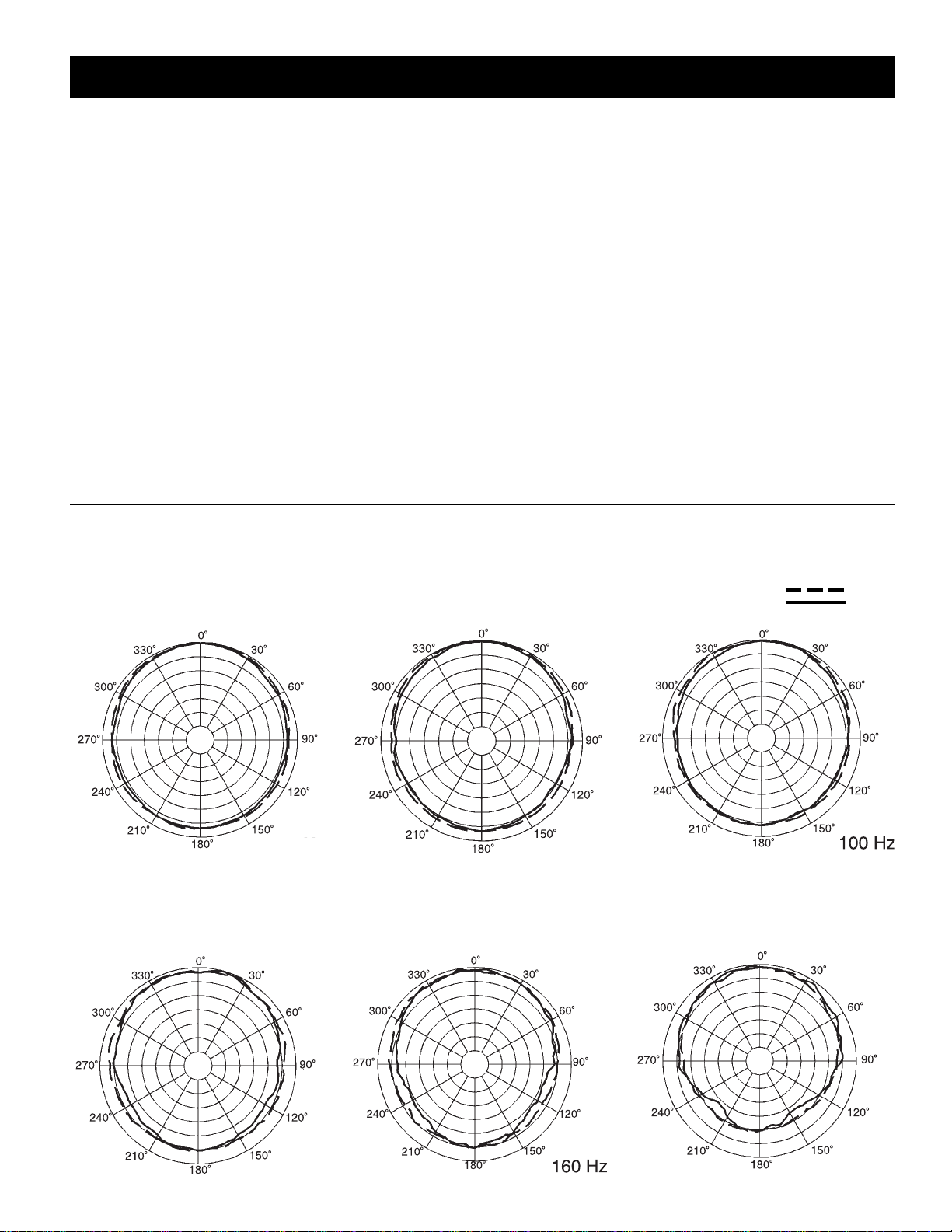
Figure 1 — Polar Response
The directional response of the Xb was measured in an anechoic environment at a distance of 6.1 m (20 ft.) using 1/3-octave-filtered pink
noise with a full spherical measurement system. The polar response of the loudspeaker system at selected 1/3-octave frequencies is
shown. The selected frequencies are representative of the polar response of the system.
Electro-Voice Speakers and Speaker Systems are guaranteed against malfunction due
to defects in materials or workmanship for a
period of five (5) years from the date of original purchase. The Limited Warranty does
not apply to burned voice coils or malfunctions such as cone and/or coil damage resulting from improperly designed enclosures. Electro-Voice active electronics associated with the speaker systems are guaranteed for three (3) years from the date of original purchase. Additional details are included
in the Uniform Limited Warranty statement.
Electro-Voice Accessories are guaranteed
against malfunction due to defects in materials or workmanship for a period of one (1)
year from the date of original purchase. Additional details are included in the Uniform
Limited Warranty statement.
Electro-V oice Flying Hardware (including
enclosure-mounted hardware and rigging
accessories) is guaranteed against malfunction due to defects in materials or
workmanship for a period of one (1) year
from the date of original purchase. Additional details are included in the Uniform
Limited Warranty statement.
For warranty repair, service information, or
a listing of the repair facilities nearest you,
contact the service repair department at:
616/695-6831 or 800/685-2606.
For technical assistance, call: 800/234-6831.
Specifications subject to change without notice.
Vertical
Horizontal
5 dB per division
Xb Bass System
63 Hz
80 Hz
125 Hz 200 Hz
5
Page 6
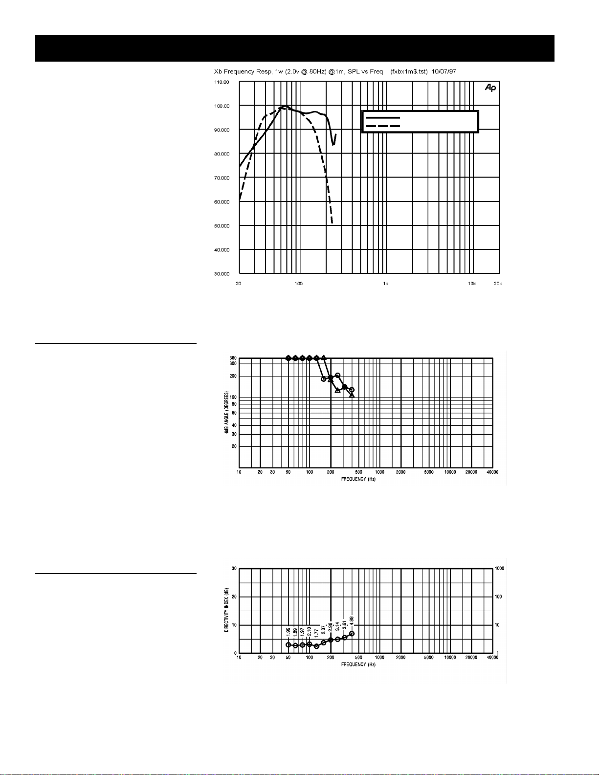
Figure 2 — Frequency Response
The frequency response of the Xb was
measured on axis in the far field in an
anechoic environment using a swept sinewave signal. The Klark Teknik DN8000 digital electronic unit was used to provide the
necessary crossover filters, equalization
and time delay. One watt of power (2.00volts rms at 70 Hz) was applied to the mid
band of the low-frequency section. The
Xb Bass System
sound pressure level was normalized for
an equivalent one- meter distance.
Xb Bass System
Without Crossover and EQ
With Crossover and EQ
Figure 3 — Beamwidth
The beamwidth of the Xb, (i.e., the included
horizontal and vertical coverage angles at
the -6-dB points) was measured with a fullspherical measurement system as described in Figure 1.
Figure 4 — Directivity
The directivity index, D
tor, R
, of the Xb were measured with a full-
, and directivity fac-
i
spherical measurement system as described in Figure 1.
DIRECTIVITY FACT OR R
θ
Q
66 66
6
Page 7
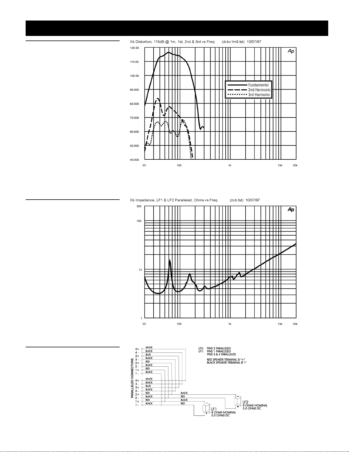
Figure 5 — Distortion
Distortion for the Xb was measured on axis
in the far field in an anechoic environment
with an input signal that would result in a
sound pressure level of 115 dB at one meter .
The Klark Teknik DN8000 digital electronic
unit was used to provide the necessary
crossover filters, equalization and time delay. The sound pressure level was normalized for an equivalent one-meter distance.
Plots of second and third harmonic distortion are shown referenced to the fundamental.
Xb Bass System
Xb Bass System
Figure 6 — Impedance
The impedance of each frequency band
of the Xb was measured in an anechoic
environment
Figure 7 — Wiring Diagram
The wiring diagram of each frequency band
of the Xb is shown.
7
Page 8
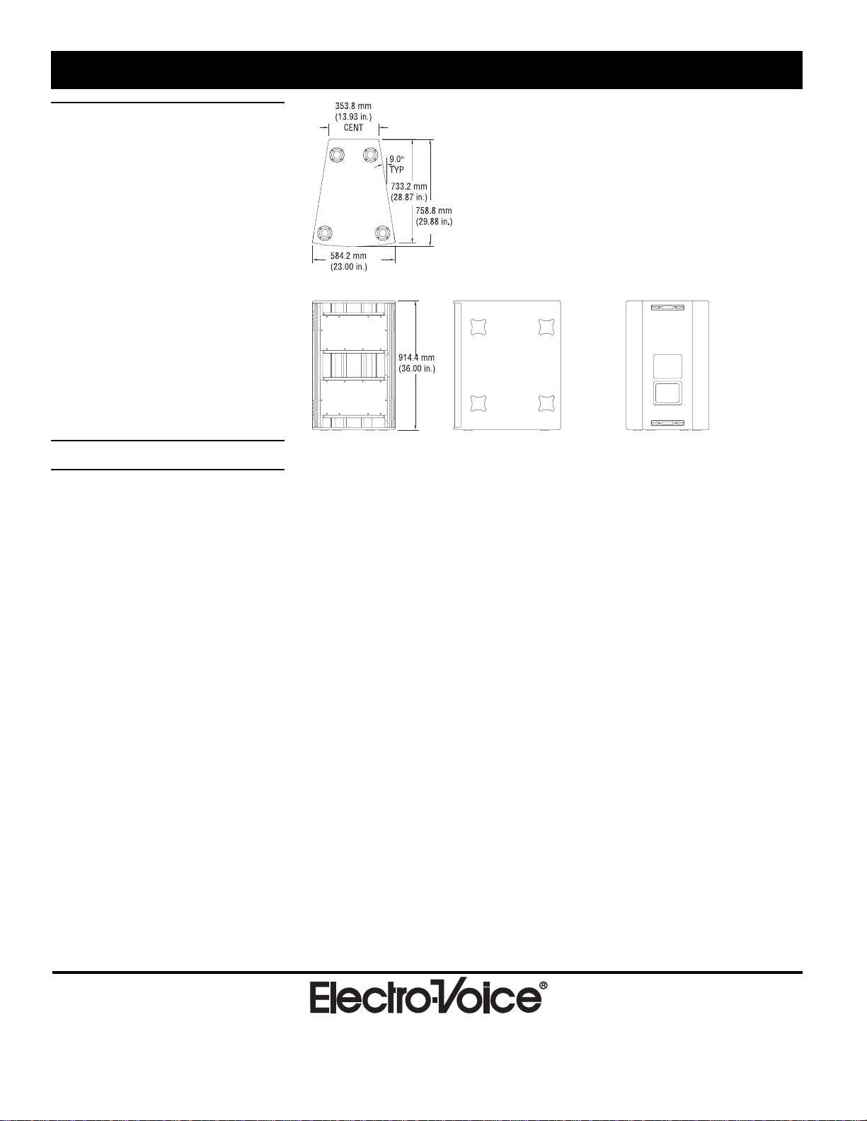
Figure 8—Dimensions
Xb Bass System
Xb Bass System
Specifications
Frequency Response (measured in far
field, with and without crossover and
equalization, calculated to one meter on
axis, swept sine wave, one watt into
system - 2.00 V at 70 Hz, anechoic
environment; see Figure 2):
37-200 Hz
Crossover Frequency:
125 Hz
Efficiency Mid Band:
5.3 %
Maximum Long-Term-Average PowerHandling Capacity (per ANSI/EIA RS426A 1980):
1,200 watts
Maximum Long-Term-Average MidBand Acoustic Output, LF/HF:
64 acoustic watts
Sensitivity (SPL at one meter, indicated
input power, anechoic environment,
average level),
1 watt:
98.5 dB
1,200 watts:
129.3 dB
Beamwidth (angle included by 6-dBdown points on polar responses,
indicated one-third-octave bands of pink
noise; see Figures 1 and 3),
Horizontal, 63-200 Hz:
240° (+120°, -60°)
Vertical, 63-200 Hz:
300° (+60°, -120°)
Directivity Factor, R
Average (see Figure 4):
(Q), 63-200 Hz
2.2 (+0.8, -0.4)
Directivity Index, D
Average (see Figure 4):
, 63-200 Hz
i
3.4 dB (+1.4 dB, -0.9 dB)
Distortion (115 dB SPL at one meter,
shaped spectrum; see Figure 5),
Second Harmonic,
40 Hz:
2.2%
80 Hz:
0.9 %
Third Harmonic,
40 Hz:
0.4 %
80 Hz:
0.2 %
T ransducer Complement,
Two EVX-180B 18-in. woofers
Impedance (see Figure 6),
Nominal:
Two 8-ohm loads
Minimum:
Two 6.4-ohm loads
Input Connections:
Two Neutrik NL8MPR Speakon
®
connectors paralleled
Recommended Amplifier Power, Rating:
800 watts per channel @ 8 ohms
(93-volts rms short term)
Enclosure Construction,
Enclosure Shell:
18-mm, 13-ply birch plywood
Finish:
Black textured paint
Grille:
Powder-coated steel with foam
Rigging: EV Proprietary hinge system at
rear. Heavy-duty L-track on front
which accepts New Haven NH32102-2
double-stud fittings
Dimensions,
Height:
914.4 mm (36.00 in.)
Width (front):
584.2 mm (23.00 in.)
Width (back):
353.8 mm (13.93 in.)
Depth:
758.8 mm (29.88 in.)
Angle:
18° wedge
Net Weight:
83.5 kg (184 lb)
Shipping Weight:
87.5 kg (193 lb)
600 Cecil Street, Buchanan, MI 49107
TM
88 88
8
616/695-6831, 616/695-1304 Fax
©Telex Communications, Inc., 1999 • Litho in U.S.A.
Part Number 534636 Rev. B—9934SPEAKERS—X-Array
 Loading...