

Page 1
Telex
Operating Instructions
SR-400
17 Channel
Synthesized Receiver
R
Page 2
SR-400 17 Channel Synthesized Receiver
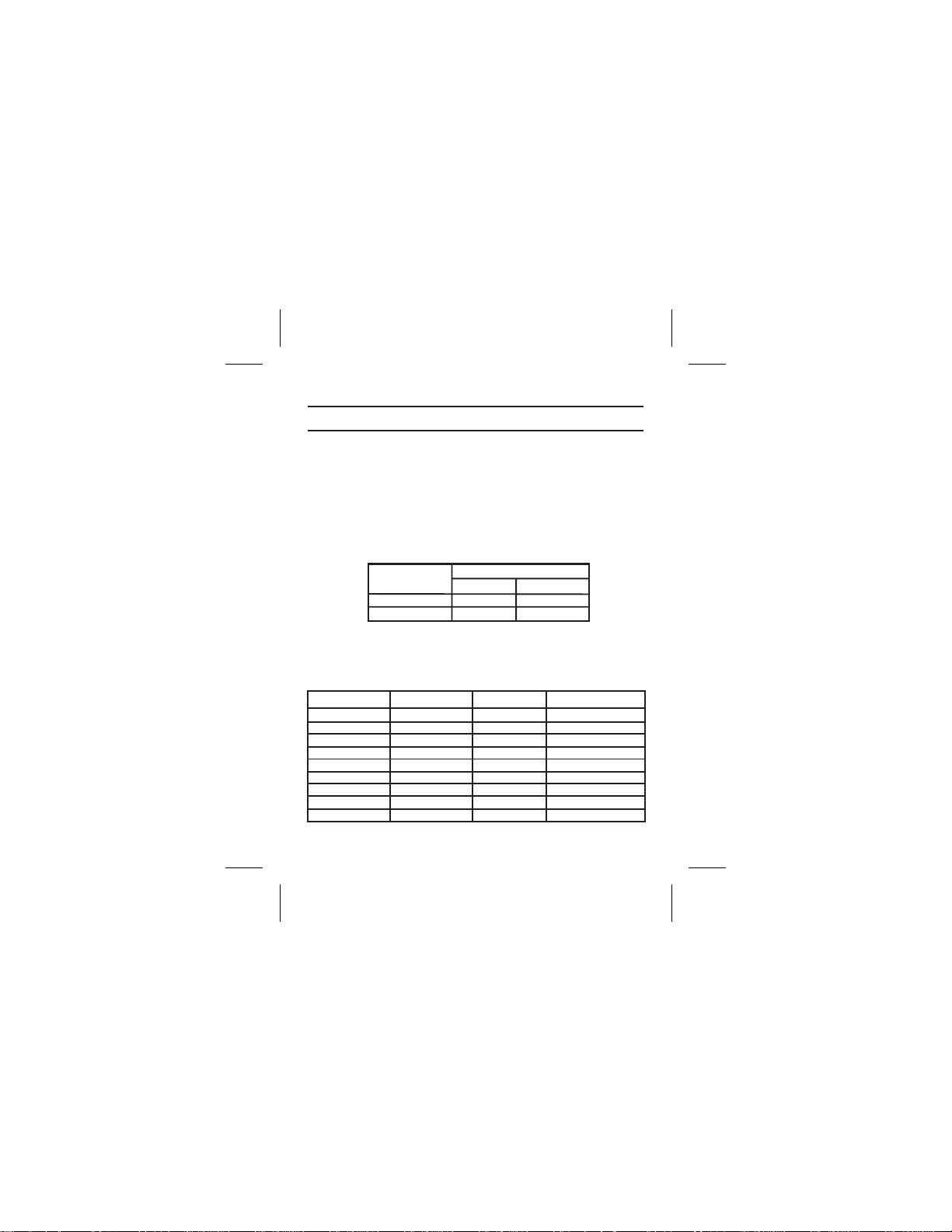
SPECIFICATIONS
Temperature Range ....................0to+50degrees C
Supply Voltage....................2-3Volts,(2)AABatteries
Battery Life...........................16-20 Hrs - Alkaline
Frequency Response 100-10 kHz .......Less than 3 dB Variation
Sensitivity (12 dB SINAD @ 74 MHz) ............... 1µVmax.
Distortion .................................less than 2%
Audio Output @10% Distortion
8-10 Hrs - Nickel-cadmium
Battery Input
Voltage 8 ohm 32 ohm
2.0V 15mW 10mW
3.0V 80mW 50mW
Controls and Connections ..........Volume OFF/ON Switch;
CHANNEL ASSIGNMENT
Channel # Freq. (MHz) Channel # Freq. (MHz)
A 72.1 J 75.5
B 72.2 K 75.6
C 72.3 L 75.7
D 72.4 M 75.8
E 72.5 N 75.9
F 72.6 O 74.7
G 72.7 P 75.3
H 72.8 Q 75.4
I 72.9
Treble Boost Button; Set Button
Audio Output Jack
-1-
Page 3
OPERATING FEATURES
Volume OFF/ON Control
This thumbwheel control serves as both an off/on switch and
as a volume control. The Receiver is turned off when the control
is in the "O" position, and the volume is loudest when the control
is in the extreme opposite position.
NOTE: The Headphone Jack must have a headphone, or
other accessory, plugged in to turn on the SR-400. Power
“ON” is indicated by the activation of the LCD display.
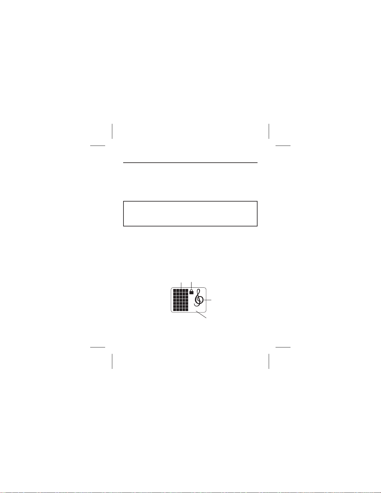
LCD Display
1. Channel Display A through Q, low battery indicator
2. Lock Indicator (see Change Lock Out)
3. High Frequency Emphasis indicator (when symbol is showing)
4. Enhanced Dynamic Range Indicator
2
1
3
E.D.R.
E.D.R.
4
LCD Display
-2-
Page 4

Channel Selection
1. Turn the receiver on and plug a listening device into the head
phone jack. A channel letter will show in the display.
2. Press the set button once and the Channel indicator will flash.
3. Press the button and the Channel will cycle up. Match the
channel to the transmitter being used (ST-200, ST-300, PST-16,
or PST-170).
4. Press SET, the channel indicator will stop flashing and the chan
nel is set.
Enhanced Dynamic Range (E.D.R.) Operation
The Telex ST -300 and PST-170 Transmitters are equipped
with E.D.R., Enhanced Dynamic Range (companded) audio.
This mode greatly improves the audio signal to noise ratio
when used with the Telex Model SR-400 receiver. The
E.D.R. mode must be selected on both the transmitter and
receiver to be effective.
1. To engage the E.D.R. function turn the SR-400 off with the volume control thumb wheel.
2. Press and hold the SET button while you turn the SR-400 back
on. The E.D.R symbol will be displayed in the lower right corner
to indicate the mode is active.
3. Repeat the procedure to disable the E.D.R. function.
-3-
-
-
Page 5

Change Lock Out
The SR-400 SET button can be locked to prevent E.D.R.
activation, and unintended channel changes. The High Fre
quency Emphasis button will remain active at all times for
the convenience of the user.
1. To engage the Lock Out Feature, press the SET and buttons at
the same time and hold them down for 10 seconds.
2. The padlock symbol will appear and the set button is disabled.
3. To unlock the system, press the SET and buttons and hold
them for 10 seconds or until the padlock symbol disappears.
Low Battery Indication
1. When there is approximately 10% of the battery life left, a battery
symbol will flash alternately with the Channel letter in the LCD display.
2. When there is only 5% battery life left, the battery symbol will
constantly flash in the display.
-4-
-
Page 6

Headphone Jack
The headphone jack accepts a 0.140-inch (3.5 mm) diame
ter miniature mono or stereo phone plug. A variety of ac
cessory units can be plugged into this jack.
SET
TREBLE
BOOST
BUTTON
E.D.R.
VOLUME OFF/ON CONTROL
HEADPHONE JACK
SWITCH
BUTTON
SET
Treble Control
A push button treble control is provided to enhance higher frequency audio. When the button is engaged, (indicated by the
in display), the treble is boosted. Push the button again to turn
feature off.
Belt Clip
The belt clip supplied is detachable by spreading the wire
apart at the tops and removing one side of the clip from the
case and then the other.
-5-
-
-
Page 7

BELTCLIP
Tel ex
SR-400
P/N:71166000
FCC ID: B5DE405
S/N:00001
BATTERY
COMPARTMENT
OPERATION
General
The Telex SR-400 Receiver is a synthesized receiver which
operates on 17 channels in the 72 to 76 MHz Band. The
SR-400 is designed to be used with the Telex AAT-2, TW-6,
PST-16, ST-200, PST-170, and ST-300 transmitters.
To operate the SR-400 Receiver:
1. Select a suitable location for the transmitter, and try to keep a
clear, unobstructed path between the transmitter and receiver an
tennas for a clear transmission.
2. Plug a receiver accessory cord from a unit such as an earphone,
headphone button receiver, induction coil neckloop, or audio-input
hearing aid into the receiver jack (the cord acts as a receiving an
tenna).
3. Turn on the SR-400 by turning the volume control wheel. Select the
correct receive channel.
-6-
-
-
Page 8

4. Adjust volume for desired comfort. (Engage treble control to en
hance “Highs” if desired.)
5. When satisfied with the channel selection and volume level, place
the Receiver in a pocket or clip it to your belt for convenience.
6. Always return the VOLUME OFF/ON control to the OFF position
when the Receiver is not in use to preserve battery life.
BATTERY REPLACEMENT
The SR-400 Receiver uses two AA alkaline batteries. Replace
weak batteries with two fresh AA alkaline batteries, and posi ti o n
them in the battery compartment as illust rat ed. 16-20 Hours of operations can be expected from alkaline batteries and 8-10 hours on
nickel-cadmium batteries.
BELT CLIP
BELT CLIPBELT CLIPBELT CLIP
BATTERY
ORIENTATION
BATTERY COMPARTMENT COVER
NOTE: If the unit is to be stored for any length of time
be sure to remove the batteries from the unit.
-7-
-
Page 9

FCC INFORMATION
The Telex Model SR-400 Receiver is Authorized under
Part 15 of the Federal Communications Commission. Li
censing of Telex equipment is the user’s responsibility
and licensability depends upon the user’s classification,
user’s application, and frequency selected.
CAUTION: Changes or modifications made by the
user could void the user’s authority to operate the
equipment.
OPTIONAL ACCESSORIES
Description Catalog No.
Earphone (single) .......................59840-005
Earphone (dual) .........................59840-007
Lightweight Headphone ...................59840-003
Full Cushion Headphone ..................63510-021
Button Receiver and 30 inch Cord ............64115-001
NL-4 Induction Coil Neckloop ...............71120-001
-8-
-
Page 10

WARRANTY INFORMATION
Model(s)_________________________ Serial No(s).:_____________________
Date of Purchase __________________________________________________
Purchased From __________________________________________________
Address _________________________________________________________
City _______________________ State______________ Zip _______________
TELEX Communications, Inc. (“Telex”)warrants to the user, who originally purchased
the serialized product delivered with this card, that the product will be free from de
fects in material and workmanship for the following periods after such date of pur
chase. Material 36 months, workmanship 36 months. Microphones, earphones,
neckloops, cables & connectors are warranted for ninety days. Telex will, at its op
tion, repair or replace free of charge such defective products subject to the follow
ing conditions:
1. Delivery of the product or parts postage prepaid to the Telex dealer, authorized ser-
2. Determination by Telex that a defect exists and is covered by limited warranty. De-
3. Repairs and replacement parts are covered under this limited warranty only for the
4. Products purchased from unauthorized dealers are not warranted.
5. You must fill out and return the product warranty card to register the purchase date o f
THIS LIMITED WARRANT Y IS EXPRESSLY IN LIEU OF ANY EXPRESS OR IMPLIED
WARRANTY, INCLUDING ANY IMPLIED WARRANTY OR MERCHANTABILITY OR
FITNESS FOR A PARTICULAR PURPOSE WHICH EX TENDS BEYOND THE T ERM
HEREOF. THE REMEDIES PROVIDED BY T HIS LIMITED WARRANTY ARE THE
ONLY REMEDIES AVAILABLE TO ANY PERSON. NO PERSON HAS ANY AUTHOR
ITY TO BIND TELEX TO ANY REPRESENTA TION O R WARRANTY OTHER THAN
THOSE PROVIDED BY THI S L IMITED WARRANTY. TELEX SHALL NO T BE LIABLE
FOR ANY INCIDENTAL OR CONSEQUENTIAL DAMAGES CAUSED BY FAILURE O R
OTHERWISE OF THE PRODUCT.
Some states do not allow exclusions or limitations of incidental or consequential dam
ages or limitations on how long an implied warranty lasts, so the limitations or exclu
sions herein may not apply to you. This warranty gives you specific legal rights, and
you may also have other rights which vary from state to state.
FILL OUT AND RETAIN THIS PORTION FOR YOUR RECORDS
LIMITED WARRANTY (VALID UNITED STATES AND CANADA ONLY)
vice facility or factory.
fects due to alteration, repair by unauthorized persons, insertion of non-Telex parts,
misuse, accidental damage, use of the equipment for purposes other than those for
which it was designed, and the like, are not covered by this limited warranty and repairs thereof will be subject to normal service charges.
unexpired term of the original limited warranty.
serialized items. A copy of the bill of sale showing the date of purchase must ac
company all warranty work.
-9-
-
-
-
-
-
-
-
-
Page 11

"
WARRANTY REGISTRATION
Limited Warranty (Previous Page)
SOUND ENHANCEMENT SYSTEMS
Detach Warranty Registration and mail to:
Telex Communications, Inc.
Burnsville, MN 55337
12000 Portland Ave. South,
Owner’s Name______________________________________________________________
Address___________________________________________________________________
City___________________________State______________ Zip______________________
Purchased From____________________________________________________________
Address___________________________________________________________________
City___________________________State______________ Zip______________________
Date of Purchase___________________________________________________________
Model No(s).:___________________ Serial No(s).:________________________________
Page 12

R
TELEX COMMUNICATIONS, INC. 12000 Portland Ave. South, Burnsville, MN 55337
PN 804013 June 2004 Made in U.S.A.
 Loading...