

Page 1
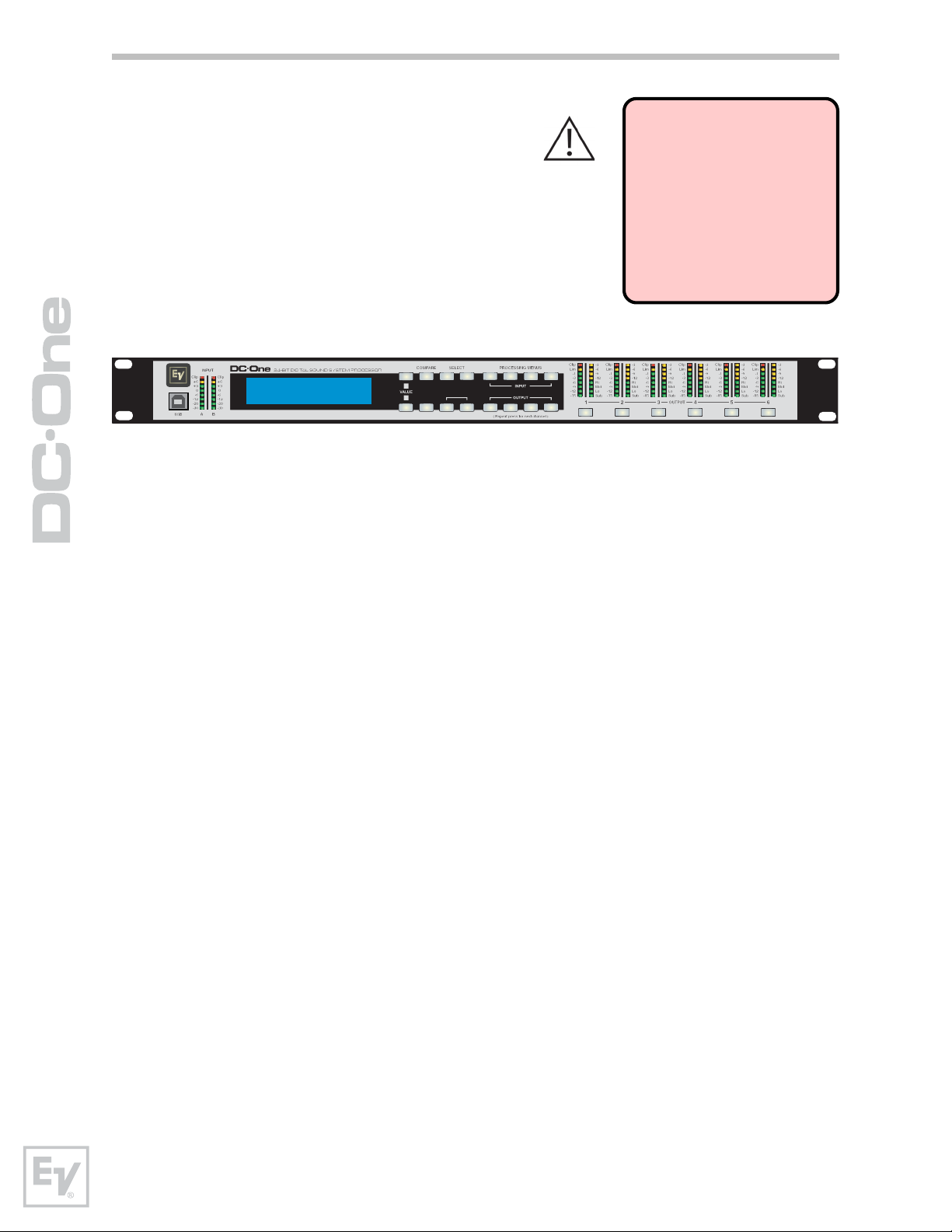
Electro-Voice DC-One M
Program:V01
(FullEdit (2in. 6out))
Edit
>
<
>
Setup
PEQ
HPF
>
X-OverRecallStore
DelayGEQ
Level
Delay
PEQ
Mute
Mute Mute
Mute
Mute
Mute
Owner’s Manual
www.electrovoice.com
Page 2

www.electrovoice.com
Page 3
equilateral triangle is intended to alert the user to the
presence of uninsulated „dangerous voltage“ within
the product’s enclosure that may be of sufficient
magnitude to constitute a risk of electric shock to
persons.
The exclamation point within an equilateral triangle is
intended to alert the user to the presence of important
operating and maintance (servicing) instructions in the
literature accompanying the appliance.
1. Read these instructions.
2. Keep these instructions.
3. Heed all warnings.
4. Follow all instructions.
5. Do not use this apparatus near water.
6. Clean only with a dry cloth.
7. Do not cover any ventilation openings. Install in accordance with the manufacture’s instructions.
8. Do not install near heat sources such as radiators, heat registers, stoves, or other apparatus
(including amplif ers) that produce heat.
9. Do not defeat the safety purpose of the polarized or the grounding-type plug. A polarized plug has two blades
with one wider than the other. A grounding type plug has two blades and a third grounding prong. The wide
blade or the third prong are provided for your safety. If the provided plug does not f t into your outlet, consult an
electrican for replacement of the obsolete outlet.
10. Protect the power cord from being walked on or pinched particularly at plugs, convenience receptacles,
and the point where they exit from the apparatus.
11. Only use attachments/accessories specif ed by the manufacturer.
12. Unplug this apparatus during lightning storms or when unused for a long period of time.
13. Refer all servicing to qualif ed service personnel. Servicing is required when the apparatus has been damaged
in any way, such as power-supply cord or plug is damaged, liquid has been spilled or objects have fallen into the
apparatus, the apparatus has been exposed to rain or moisture, does not operate normally, or has been dropped.
14. Do not expose this equipment to dripping or splashing and ensure that no objects f lled with liquids, such as vases,
are placed on the equipment.
15. To completely disconnect this equipment from the AC Mains, disconnect the power plug from the AC receptacle.
16. The mains plug of the power supply cord shall remain readily operable.
European Union and other European countries with individual national policies on the management of
WEEE) The symbol on the product or on its packaging indicates that this product may not be treated as
regular household waste, but has to be disposed through returning it at a Telex dealer.
IMPORTANT SERVICE INSTRUCTIONS
CAUTION:
electric shock, do not perform any servicing other than that contained in the Operating
Instructions unless you are qualif ed to do so. Refer all servicing to qualif ed service personnel.
1. Security regulations as stated in the EN 60065 (VDE 0860 / IEC 65) and the CSA E65 - 94 have to be obeyed when
servicing the appliance.
2. Use of a mains separator transformer is mandatory during maintenance while the appliance is opened, needs to be
operated and is connected to the mains.
3. Switch off the power before retrof tting any extensions, changing the mains voltage or the output voltage.
4. The minimum distance between parts carrying mains voltage and any accessible metal piece (metal enclosure),
respectively between the mains poles has to be 3 mm and needs to be minded at all times. The minimum distance
between parts carrying mains voltage and any switches or breakers that are not connected to the mains (secondary
parts) has to be 6 mm and needs to be minded at all times.
5. Replacing special components that are marked in the circuit diagram using the security symbol (Note) is only
permissible when using original parts.
6. Altering the circuitry without prior consent or advice is not legitimate.
7. Any work security regulations that are applicable at the location where the appliance is being serviced have to be
strictly obeyed. This applies also to any regulations about the work place itself.
8. All instructions concerning the handling of MOS - circuits have to be observed.
These servicing instructions are for use by qualif ed personnel only. To reduce the risk of
SAFETY COMPONENT ( MUST BE REPLACED BY ORIGINAL PART )NOTE:
Page 4

Contents
Introduction .........................................................8
DC-One Features ..................................................................... 8
Controls & Connection.......................................... 10
Front Panel ............................................................................10
Rear Panel .............................................................................14
Installation ............................................................................16
Mounting.................................................................................................... 16
Power Connection........................................................................................ 16
Audio Cables .............................................................................................. 16
Balance Input / Output Connections ............................................................... 16
Un-balanced Input / Output Connections ........................................................ 17
RS-232 ...................................................................................................... 17
Relay Contact Closure .................................................................................. 17
USB .......................................................................................................... 18
Connection to Amplifiers............................................................................... 18
Input Level Adjustment ................................................................................ 18
Editing & Operation ............................................. 19
Factory Presets.......................................................................19
User Presets – Standard Editing ...............................................19
User Preset – Full Editing ......................................................... 19
Unpacking & Warranty............................................................. 19
Run-time Mode ................................................... 20
LCD Display ...........................................................................20
Input Level Meters ..................................................................20
Output Level Meters ................................................................ 20
Output Gain Reduction Meters ..................................................21
Output Channel Mute Buttons...................................................21
Output Channel Function Indicators .......................................... 21
Preset Recall .......................................................................... 21
Preset Store...........................................................................22
Edit ......................................................................................23
Standard Edit Mode ................................................................23
Full Edit Mode ........................................................................23
Parameters ............................................................................23
Input Channel Hi-Pass Filter.......................................................................... 24
Input Channel Parametric EQ ........................................................................ 25
Input Channel GEQ (Graphic Equalizer) .......................................................... 28
Input Delay ................................................................................................ 28
Page 5

Routing ...................................................................................................... 29
Cross-Over (Output Channels) ...................................................................... 29
Parametric EQ (Output Channels) .................................................................. 31
Delay (Output Channels) ............................................................................. 31
Channel Level (Output Channels) .................................................................. 32
Channel Limiter (Output Channels) ................................................................ 32
Setup ................................................................ 33
Setup Menus .......................................................................... 33
Configuration .............................................................................................. 33
Input ......................................................................................................... 34
LCD ........................................................................................................... 34
Limiter Units ............................................................................................... 34
Metering .................................................................................................... 34
Temperature ............................................................................................... 34
Editing ....................................................................................................... 35
Lock - Front Panel Access ............................................................................. 35
System ...................................................................................................... 36
RS232 Port ................................................................................................. 36
Configurations of the DC-One ................................ 37
List and Detailed Descriptions .................................................. 37
Stereo 2 Way + Full Range ........................................................................... 38
3 Way Stereo.............................................................................................. 39
4 Way + FR ................................................................................................ 40
5 Way + FR ................................................................................................ 41
Free Configuration - Full Edit 2 in 6 Out .......................................................... 42
3 Way Stereo-Mono Sub+FR ......................................................................... 43
EQ Plot Images ................................................... 45
6dB PEQ Cuts Q Changes.........................................................45
6dB-Oct Shelves at 200Hz and 2kHz .........................................45
12dB PEQ Cuts Q Changes ....................................................... 46
12dB-Oct Shelves at 200Hz and 2kHz ....................................... 46
Bessel Filters ......................................................................... 47
Butterworth Filters .................................................................. 47
Hi Lo Pass Filters .................................................................... 48
Linkwitz-Riley Filters ...............................................................48
PEQ Gains .............................................................................49
Operation Modes & Presets ................................... 50
Dimensions ........................................................ 52
Technical Specifications ........................................ 53
Page 6
Overview
Input Meters
Electro-Voice DC-One
Program:U01
(FullEdit (2in. 6out))
Compare / Edit
ValueDisplay
>
>
Select Buttons
Edit
Setup
<
>
RecallStore
USB Port
Setup
Store / Recall
6
Page 7
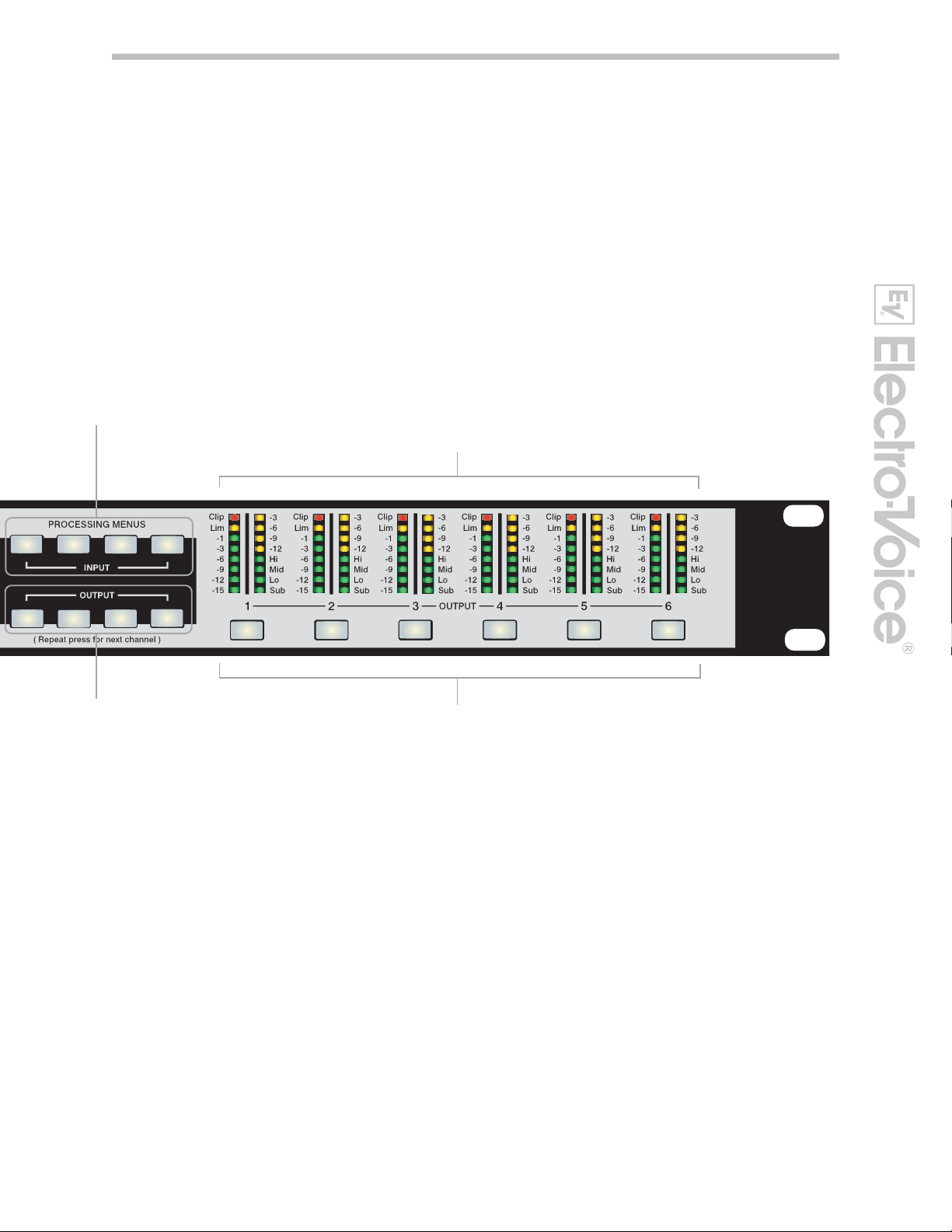
Processing Menues for High
Pass Filter, Parametric EQ,
Graphic EQ and Delay
PEQ
HPF
X-Over
PEQ
Delay
DelayGEQ
Level
Mute
Mute
Output Gain Reduction Meters, Output Channel Function Indicators and
Output Level Meters
Mute Mute
Mute
Mute
Output Control buttons for
Cross-Over, Parametric
EQ, Delay and Level
Output Channel
Mute Buttons
7
Owners Manual
Page 8
Introduction
Thank you for purchasing the Electro-Voice
DC-One Digital Signal Processor.
The Electro-Voice DC-One Digital System
Processor is a universal two-input, six-output
digital signal processor with the flexibility of
configuration to handle a multitude of audio
system needs and applications; installed sound,
house of worship, convention & meeting facilities,
concert touring, club, portable sound
reinforcement and more.
IMPORTANT NOTE
To achieve optimum performance and guard against
damage to the processor,
your sound system or yourself, please read, understand
and follow all of the directions contained in this
Owner’s Manual. Failure to
do so may result in improper
performance, loss or injury.
Electro-Voice DC-One
Program:U01
(FullEdit (2in. 6out))
Edit
>
<
>
Setup
PEQ
HPF
>
X-OverRecallStore
DelayGEQ
Level
Delay
PEQ
Mute
Mute Mute
Mute
Mute
Mute
DC-One Features
The internal routing matrix can be configured as 2-way stereo + full-range, 3-way
stereo, 4-way mono + full-range, 5-way mono + full range, 3-way stereo with a
mono sub + full-range, 4-way stereo with mono sub and low frequency and finally
as a freely assignable 2 x 6 matrix router.
The DC-One replaces entire racks of signal processors previously needed to
properly configure and control sound reinforcement systems with a single
Analog Devices® SHARC™ DSP processor. The substantial advantages of the
DC-One over discrete signal processing racks include:
• 24-bit, 48kHz digital signal path
• No patch cables to fail or add noise
• Optimal gain structure throughout all stages of signal processing;
no gain matching from processor to processor.
• Recallable factory and user presets; instant system reconfiguration
for differing applications and performances.
• Easy, intuitive operation and editing with a PC and the DC-One
Graphic User Interface Application.
Each DC-One Digital System Processor includes the following signal
processing blocks:
• Input VU Metering
• Analog or AES/EBU inputs
• 24-bit, 48kHz A/D converters
• Stereo Hi-pass filters
• Stereo 9-band parametric equalizer
• Stereo 31-band graphic equalizer (available as a software add-on
with V1.1 firmware-see www.electrovoice.com for details)
• Stereo delay
8
Page 9

Matrix Router / Mixer
• Two (stereo) inputs
• Summed left / right (mono) input
• Six assignable outputs
Outputs (each)
• Cross-over (hi-pass / low-pass filters), with selectable filter types
• 5-band parametric equalizer
• Delay
• Polarity
• Peak RMS detecting limiter
• Level & Mute
• 24-bit, 48kHz D/A converters
Additional features include:
• Electronically balanced XLR inputs and outputs
• -6dBu switchable input level pad
• Contact closure interface for recall of up to eight selectable presets
• Front-panel USB port for connection to PC; preset editing and real
time parameter control and monitoring.
• Firmware updates
• FLASH memory for preset storage and in-field firmware upgrades
• Input level meters
• 192 x 32 back-lit graphic LCD display
• LCD navigation / editing controls
• DSP block navigation short-cut controls
• Output level meters
• Output gain reduction meters
• Output assignment display LEDs; sub, low, mid & high
• Output channel Mute controls
• Auto-ranging internal power supply; 100 – 240VAC, 50 – 60Hz
• Standard IEC A.C. inlet with external, replaceable fuse
9
Owners Manual
Page 10
Controls & Connection
Front Panel
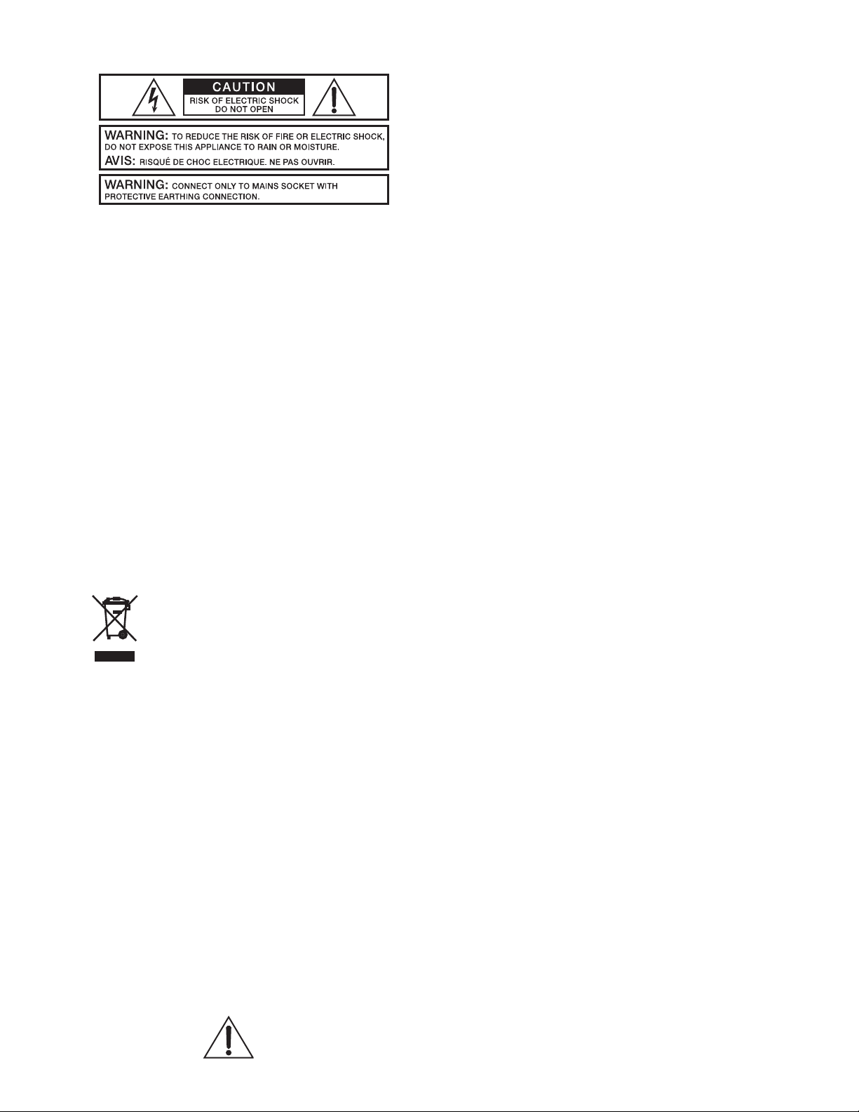
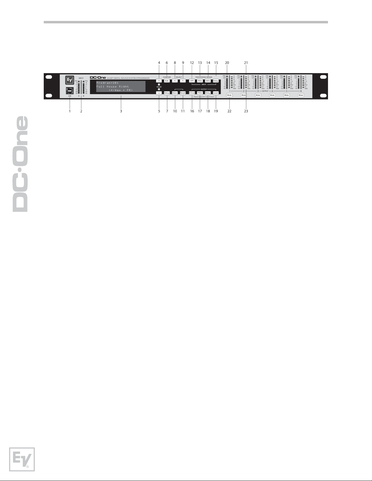
1 – USB Connector
USB 1.0 port for connection to a PC running Windows XP or Vista. With a
connected PC you may run the DC-One Editor Graphic User Interface Application.
The DC-One can be operated, edited and configured for installation with an easy
to use, intuitive interface. Any available firmware updates downloadable from
www.electrovoice.com can be loaded via the USB port as well; allowing for easy
in-field updates.
2 – Input Level Meters
The DC-One does not itself have input level controls. Proper input level
adjustment is accomplished by setting the output level from the (L / R) bus
outputs from the connected mixer (or other audio output device), as the vast
majority of today’s mixer-outputs are dBu calibrated. When the mixer is operating
at optimal levels, so is the DC-One. The input meters monitor the input level of
either analog or AES-EBU inputs, depending on the input mode selection set in
the Setup Menu.
Optimal signal-to-noise performance is obtained when the nominal (average),
input level consistently lights the +3dBu (green) and / or +6dBu (Yellow) LED
indicators. As the DC-One is a digital audio device – and digital clipping produces
very unpleasant results, the Clip (red) LED should not light. If the DC-One’s input
does clip, reduce the output level of the connected mixer.
3 – LCD Display
The back-lit, 192 x 32 graphic LCD display allows for operation and editing of the
DC-One without the need for an attached PC. The contrast can be set in the Setup
Menu for varying lighting conditions and viewing angles.
The LCD display works in conjunction with Menu buttons, Select buttons and
Value buttons - to operate, navigate and edit the DC-One’s parameters.
In Run mode, the LCD displays the number and name of the currently selected
factory or user preset. Pressing the Recall or Store buttons switches to their
respective menus. Pressing the Edit or Setup menu buttons switches the display
to the last edited parameter.
In Edit and Setup mode, the top line of the LCD display shows the currently
selected parameter edit screen. Use the Select buttons to activate the top line of
the display, and the value buttons to scroll through available parameter edit
screens.
10
Page 11

4/5 – Value Up/Down Buttons
Depending on the current LCD screen, the Value Up/Down Buttons performs
the following function:
Recall – Select forwards/backwards through the stored preset list to
select a preset to be recalled to current memory.
Store – Select User Preset destinations forwards/backwards to select a
destination for the currently edited preset, scroll forwards through ANSI
character set to name preset.
Edit / Setup – Scroll forwards/backwards through Edit / Setup screens
when the top line of the LCD screen is active. Scroll forwards through
values for the selected parameter in an Edit / Setup screen.
6 – Edit / Compare Button
Pressing the Edit button while in Run mode places the current preset in Edit
mode and the Edit button lights. The LCD display shows the last edit screen
that was selected. From this point, any edit screen can be displayed and
altered.
Pressing the Edit button again “compares” the edited preset, if parameters
have been altered, to the original un-edited preset. This compare function will
audibly switch between the altered parameters and the previously stored
settings, allowing you to hear the effect of any DSP changes that have been
made. Use this feature to monitor progress in editing or creating presets.
Subsequently recalling a new preset will prompt you to save changes, which
you may do or not.
7 – Setup Button
Pressing the Setup button while in Run mode displays the Setup menus in the
LCD display and the Setup button lights. In this mode, any Setup menu can
be displayed and altered. Changes made to Setup menu items are saved
automatically.
To exit Setup mode, press the Setup button again. The LCD display will revert
to Run mode.
8 – Select < Button
The Select < button is pressed to navigate backwards through Edit, Setup
and / or Recall menu displayed. The button cycles through all available value
fields in a screen and wraps around from first to last.
9 – Select > Button
The Select > button is pressed to navigate forwards through Edit, Setup and /
or Recall menu displayed. The button cycles through all available value fields
in a screen and wraps around from last to first.
11
Owners Manual
Page 12

10 Store Button
Pressing the Store button while in Run mode displays the Store Preset screen
in the LCD display and the Store button lights. In this screen edited presets
can be named and saved to a user preset location. Pressing the Store button
again completes the preset save operation.
To exit without storing the current preset, press the Edit or Setup buttons to
return to the Run mode screen.
11 – Recall Button
Pressing the Recall button while in Run mode displays the Recall Preset screen
in the LCD display and the Recall button lights. In this screen, any of the 60
factory and 20 user presets can be recalled into current memory. Pressing the
Recall button again completes the preset load operation and returns the LCD
display to Run mode.
To exit without recalling a preset, press the Edit Or Setup buttons to return to
the Run mode screen.
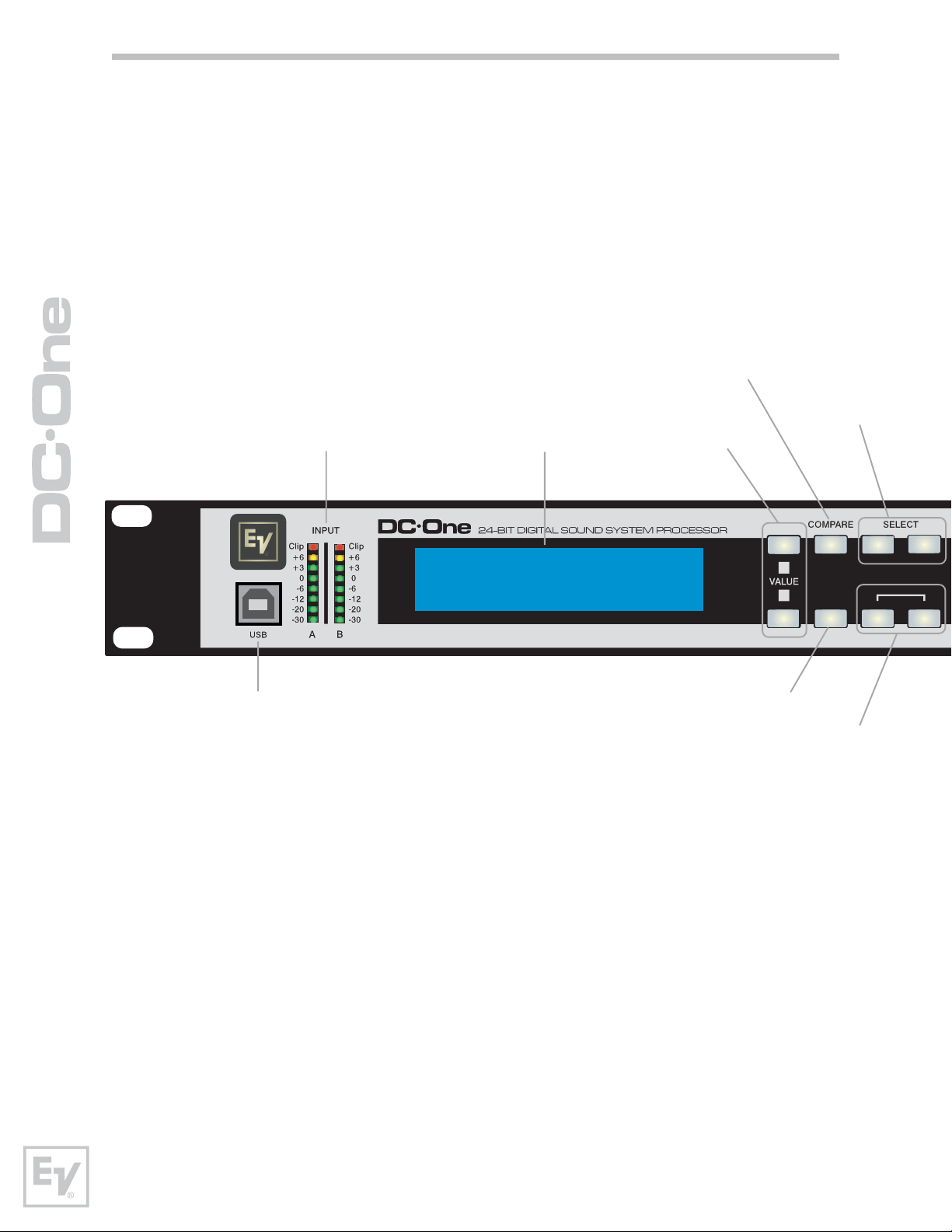
12 – Input HPF Button
Pressing the HPF button places the current preset in Edit mode and jumps to
the Hi-Pass Filter screen of Input A. Subsequent button presses toggle the
display between Input A and Input B.
13 – Input PEQ Button
Pressing the PEQ button places the current preset in Edit mode and jumps to
the first screen of the Input Parametric Equalizer. Subsequent button presses
toggle the display between Input A and Input B.
14 – Input GEQ Button
Pressing the GEQ button places the current preset in Edit mode and jumps to
the the Input Graphic Equalizer screen. Subsequent button presses toggle the
display between Input A and Input B.
15 – Input Delay Button
Pressing the Delay button places the current preset in Edit mode and jumps
to the Input Delay screen. Subsequent button presses toggle the display
between Input A and Input B.
16 – Output X-Over Button
Pressing the X-Over button places the current preset in Edit mode and jumps
to the first Output Channel Cross-Over screen. Subsequent button presses
step through the six output channels.
12
Page 13

17 – Output PEQ Button
Pressing the PEQ button places the current preset in Edit mode and jumps to
the first Output Parametric Equalizer screen. Subsequent button presses step
through the six output channels.
18 – Output Delay Button
Pressing the Delay button places the current preset in Edit mode and jumps
to the Output Channel Delay screen. Subsequent button presses step through
the six output channels.
19 – Output Level Button
Pressing the Level button places the current preset in Edit mode and jumps to
the Output Channel Level screen. Subsequent button presses step through
the six output channels.
20 - Output Level Meters
Each output channel has an eight-segment output level VU meter. Meter
response characteristics can be selected in the Setup menu: Normal Fast,
Peak-Hold Slow Decay. The yellow segment indicates that limiting is being
applied to the output channel. The red segments indicates clipping of the D/A
converters and should be avoided by adjusting the Output Level of the output
channel. It is important to understand how the meters work and what they
are displaying. The Output Meters are displayed as “dB to Limiter Threshold”.
In other words, these meters will display the headroom between the output
level and the limiter threshold. When viewed in conjunction with the Gain
Reduction meters, this provides a complete display of level and headroom
before and after limiting has been engaged to allow system levels to be
optimized.
This also means that the output metering will be displayed differently
depending on the limiter threshold setting.
21 – Output Gain Reduction Meters
Each output channel has a four-segment gain reduction meter that shows the
effect of the output channel Limiter on output level; from 0dBu to -12dBu.
22 – Output Channel Mute Buttons
Each output channel has a lighted Mute button. Pressing the Mute button
turns off the output of that channel. The button lights red as an alert. Press
the Mute button again to restore the output channel’s signal.
Output channels may also be muted from the DC-One Graphic User Interface
Application, if the unit is connected to a PC. Muting a channel in any window
of the application will light the channel Mute button on the front panel of the
unit as well.
13
Owners Manual
Page 14
23 – Output Channel Function Indicators
Each output channel has a four-segment function display for informational
purposes only. For any given configuration possible with the DC-One, an
output channel may be identified as a sub, low, low/mid, mid, mid/hi, hi or
full range output. One or two adjacent LED are displayed to indicate all
possible output bandpasses. (Full range is indicated by no lit LED’s.)
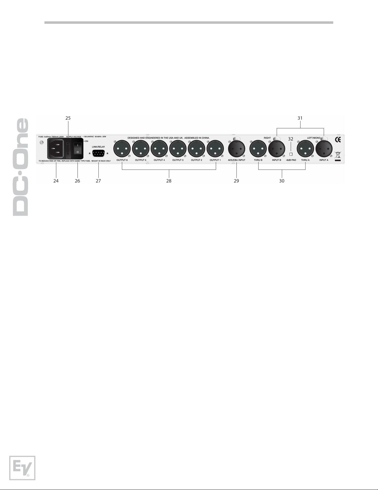
Rear Panel
24- A.C. Inlet
The DC-One features a standard IEC A.C. inlet that will accept universal
power cords. The DC-One power supply is auto-ranging and can accept
voltages from 100 - 240VAC, 50 – 60Hz. Only A.C. cords approved for use in
your country should be connected to the DC-One.
25 – A.C. Fuse
The A.C. inlet includes a fuse holder that contains the mains fuse as well as a
spare fuse. If necessary, replace the fuse only with a specified 5x20mm,
T800mA, L250V replacement. Disconnect A.C. power before replacing a fuse.
Before turning the unit back on, assess the condition of the A.C. receptacle
powering the DC-One. If fuses continue to blow, refer servicing of the DC-One
only to qualified service personnel.
26 – A.C. Power Switch
The A.C. power switch turns power to the DC-One On and Off.
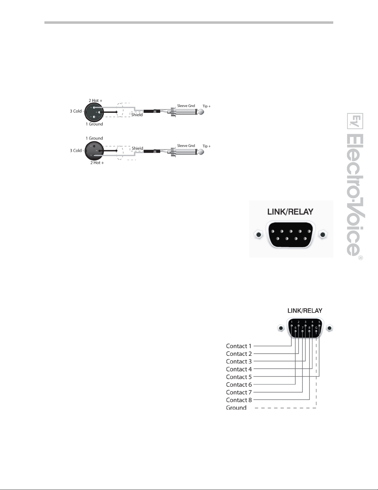
27 – Link/Relay Interface
The operating mode of this dual purpose interface is selected in the Setup
menu. Operating modes are:
RS-232 Interface – Used to link two DC-Ones together in a Master /
Slave setup. Connection is made via a standard 9-pin null-modem serial
interface cable with female connectors.
Contact Closure Port – Eight contact closure pins plus ground for
interfacing to 5v contact closure systems. Each pin can be assigned a
preset that is recalled when voltage on that pin is detected. The lowest
pin number takes priority in multiple controller systems.
14
Page 15

28 – Balanced XLR Outputs
Each output channel has an electronically balanced XLR connector for
connection to system amplifiers. Each output channel can output different
frequency ranges depending on its assignment and cross-over settings.
Care must be taken to assure that each output is
connected to an appropriate amplifier and loudspeaker to
avoid damage or unexpected results. Note that a new
preset may change the assignment of channel and its
frequency range. For instance an output assigned to Hi
frequency speakers in one preset, may be assigned as a
sub output in another. See chapter “Configurations of the
DC-One” for connection examples.
29 – AES/EBU Digital Input
In addition to the analog audio inputs, an AES/EBU digital stereo input is
provided and selectable in the Setup menu. The input conforms to IEC
standard 60958 Type I. Connections must be made with three-conductor,
110-Ohm, twisted pair cabling and an XLR connector.
30 – Balanced XLR Thru
Each analog audio input is connected to an electronically buffered and
balanced output as a through connector. The signal does not go undergo any
digital conversion or processing. These connectors are used to pass input
audio to a second DC-One used as a slave or to other audio inputs in the
system.
31 – Balanced XLR Inputs
Each input has an electronically balanced, locking XLR connector. In stereo or
dual modes, connections to both inputs must be made. In mono modes, only
one connection need be made, typically to Input A.
32 – -6dB Pad
Input levels to the DC-One can be reduced -6dB prior to the A/D converter to
compensate for higher-level output from mixers and other audio devices. For
ideal signal to noise performance when connecting the DC-One to high output
level devices engage the -6dB pad rather than turning down the output of the
connected device. The DC-One’s Input Level Meters (2) will indicate incoming
signal level and whether attenuation is required.
15
Owners Manual
Page 16
Installation
For proper operation, all directions regarding installation and connection must be
followed.
Mounting
The DC-One should be mounted in a rack-mount enclosure or rack rails. The
unit is 1RU tall by 14” (353mm) deep. Proper clearance for air circulation
around the unit must be provided. Do not block any vent holes on the unit.
For secure mounting and electrical insulation, correct rack screws must be
used – #10-32 screw with plastic / nylon cup washer. All four mounting points
provided by the rack ears must be secured.
Power Connection
The DC-One must be connected to A.C. power only by means of the provided
IEC A.C. cable or by a power cable provided by the dealer / installer to match
the configuration of your country or region. The DC-One must only be
connected to a properly wired, three pin, grounded A.C. outlet. A.C. power
must range from 100 – 240VAC, 50 – 60Hz. The DC-One internal power
supply is an auto-ranging design; no adjustments are necessary to configure
it for proper A.C. power.
Audio Cables
Always use correctly shielded audio cables when connecting to the DC-One.
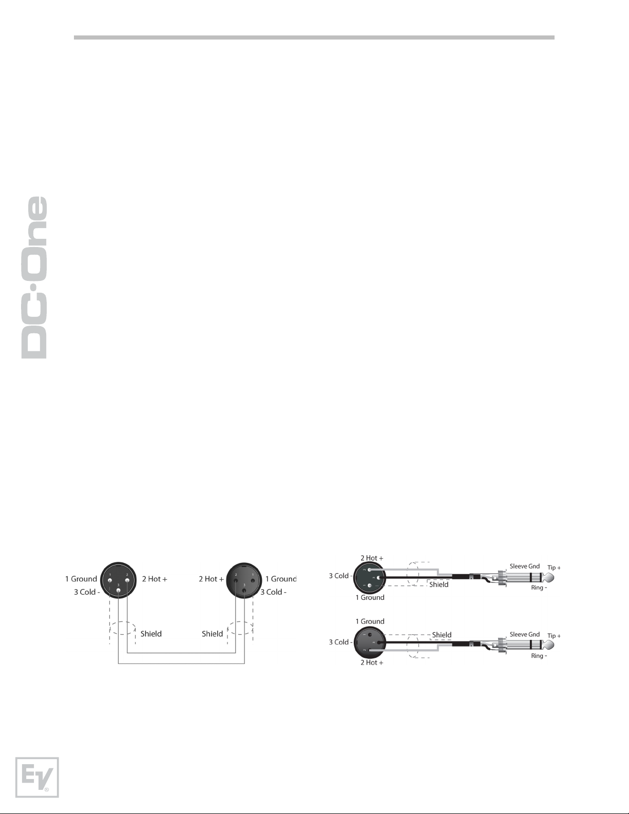
Balance Input / Output Connections
To minimize induced noise caused by audio cables and to maximize the length
of cables used, balanced connections are strongly advised for both Inputs and
Outputs. The XLR jacks provided on the DC-One are configured as pin 1
ground, pin 2 hot (+), pin 3 cold (-). Cable shielding must be connected to
pin 1. XLR – XLR cables or ¼” tip-ring-sleeve – XLR cables can both be used
for balanced connections to the DC-One.
16
Page 17
Un-balanced Input / Output Connections
Un-balanced connections can be made to the DC-One, although induced noise
from cabling may be increased. Cables should also be less than 15” (5m) in
length. Unbalanced connections can be 6dB lower in level as well. To match
the audio level obtained with a balanced connection, it is necessary to tie pin
3 to ground at the XLR connector. This may increase noise.
RS-232
Two DC-Ones can be used in combination as a
Master / Slave for managing larger sound
reinforcement systems. A 9-pin D-sub connector is
provided on the rear of each unit for data line
connections. A standard female-to-female RS232
cable that conforms to the null modem wiring
convention is used to connect the two units. Cable
length should be kept to less than 45 feet (15m) for
the most reliable operation. These cables are readily
available at local computer dealers.
Operation of the DC-One 9-pin port for RS-232
connections is selected in the Setup menu.
Relay Contact Closure
The same 9-pin port used for RS-232
connection to another DC-One can
alternately be used to recall presets
from relay contact closures. Pins 1 – 8
are the input lines and pin 9 provides
the ground reference. When the DC-One
detects a connection between pin-9
ground and pins 1 – 8, as completed by
an external relay, a preset assigned by
the user to pins 1-8 is recalled into
memory and the DC-One returns to runtime mode.
17
Owners Manual
Page 18

USB
Connecting the DC-One to a PC for operation via the DC-One Graphic User
Interface application is accomplished via the front panel USB port. The port
conforms to the USB 1.0. Type B specification. Type B USB cables are readily
available at computer dealers.
Connection to Amplifiers
It is very important to confirm correct connection to all amplifiers.
The DC-One has the ability to configure each output for a
specific frequency range; sub, low freq. mid freq, high freq.
You must make sure that each output is connected to the
correct amplifier and loudspeaker(s). Incorrect connections
could lead to unexpected results or damage to loudspeaker
components.
Note also that each preset in the DC-One includes DSP and
bandpass parameters for the output channels. It is possible
for a new preset to change an output from Hi to Sub, for
instance. Make sure that connections to amplifiers and
loudspeakers are correct before using a new preset.
Input Level Adjustment
The final step in setting up, installing and connecting the DC-One is to set
proper input levels to the unit. The DC-One does not itself have input level
controls. Proper input level setting is accomplished by setting the output level
from the (L / R) bus outputs from the connected mixer (or other audio output
device). The input meters monitor the input level of either analog or AES/EBU
inputs, depending on the input mode selection set in the Setup Menu.
Optimal signal-to-noise performance is obtained when the nominal
(average), input level consistently lights the +3dBu (green) and /
or +6dBu (Yellow) LED indicators. As the DC-One is a digital audio
device – and digital clipping produces very unpleasant results – the
Clip (red) LED should never light. If it does, reduce the output level
of the connected mixer.
Input levels to the DC-One can be reduced -6dB with the
rear panel pad switch to compensate for higher-level
output from mixers and other audio devices. For ideal
signal to noise performance when connecting the DCOne to high output level devices, engage the -6dB pad
rather than turning down the output of the connected
device.
18
Page 19

Editing & Operation
Factory Presets
The DC-One comes with 60 factory presets to configure and manage typical sound
reinforcements systems. Factory presets can be recalled at will. Limited editing
can be performed from the front-panel LCD user interface such as output level,
mute and limiter threshold setting. Installers can identify factory presets with
system configurations that are not appropriate for the given installation and lockout and hide them from the operator.
User Presets – Standard Editing
The DC-One uniquely allows for limited access
to and visibility of parameters. Via the DC-One
Graphic User Interface Application, the installer
can determine which parameters may be
accessed.
For more on Standard and editing see
page 22.
User Preset – Full Editing
The DC-One can also be configured in full-edit
mode. All matrix routing presets are available
including 2 x 6 Full Edit. All DSP parameters
are accessible and adjustable. Resulting
settings can be saved into 20 User Preset
locations for later recall. Editing can be
performed from the front-panel LCD display or
on a PC with the DC-One Editor Graphic User Interface Application. Full editing is
recommended only for experienced installers / operators.
Unpacking & Warranty
Carefully remove the DC-One from its packaging and packaging materials. Please
save all packing materials and box, should you ever need to return the DC-One
for warranty service.
Included with the DC-One is this Owner’s Manual, Quick Start Guide, Warranty
card, DC-One Graphic User Interface Application CD, and A.C. power cable.
Contact your distributor, dealer or installer if any of these items is not included.
Fill out the warranty card in its entirety and return it to the address noted. Only
products for which completed warranty cards have been received will be covered
fully under warranty.
years), from the date of purchase. Please save the warranty certificate and
receipt; which must be presented at the time of warranty service for the factory
warrantee to be valid.
1 Warranty coverage rights vary by state and country. Your warranty rights may vary. Consult your distributor,
dealer or installer for your warranty rights.
1
The factory warranty for your DC-One is 36 months (3
19
Owners Manual
Page 20

Run-time Mode
LCD Display
On power-up, the DC-One boots and displays
the run-time screen. The current preset
memory location and name are displayed as
well as the configuration on which the preset is
based.
Caution Before operating the sound reinforcement system, and any time a new preset is
recalled, check the configuration display to make sure that it is appropriate for your system
and that connections to your system are correct for the current configuration. Failure to do so
could cause unexpected results or damage to the system or its components.
The LCD display’s contrast can be adjusted in
the Setup Menu to accommodate different
viewing angles.
Input Level Meters
During operation, the left and right input level meters display the
signal present at the DC-One’s analog and Digital inputs. The DCOne does not itself have input level controls. Proper input level
setting is accomplished by setting the output level from the (L / R)
bus outputs from the connected mixer or other audio source.
Optimal signal-to-noise performance is obtained when the nominal
(average), input level consistently lights the +3dBu (green) and /
or +6dBu (yellow) LED indicators. As the DC-One is a digital audio
device – and digital clipping produces very unpleasant results – the
Clip (red) LED should never light. If it does, reduce the output level
of the connected mixer.
Output Level Meters
Each output channel has an
eight-segment output level
VU meter. Meter response
characteristics can be
selected in the Setup menu:
Normal Fast, Peak-Hold or Slow Decay. The yellow segment indicates that limiting is
being applied to the output channel. It is important to understand how the meters
work and what they are displaying. The Output Meters are displayed as “dB to
Limiter Threshold”. In other words, these meters will display the headroom between
the output level and the limiter threshold. When viewed in conjunction with the Gain
Reduction meters, this provides a complete display of level and headroom before
and after limiting has been engaged to allow system levels to be optimized. This also
means that the output metering will be displayed differently depending on the limiter
threshold setting. The red segments indicates clipping of the D/A converters and
should be avoided by adjusting the Output Level setting of the output channel.
20
Page 21

Output Gain Reduction Meters
Each output channel has a four-segment gain reduction meter that
shows the effect of the output channel Limiter on output level; from
0dBu to -12dBu. Output limiting can be bypassed by entering Edit mode,
selecting Output Channel Limiter and selecting a limiter threshold of +21
dBu (8.205V) or turning the Bypass parameter to “On”.
Output Channel Mute Buttons
Each output channel has a lighted Mute button. Pressing the Mute button turns off
the output of that channel. The button lights red as an alert. Press the Mute
button again to restore the output channel’s signal.
Mute
Mute
Mute Mute
Mute
Mute
Output Channel Function Indicators
Each output channel has a four-segment function display for informational
purposes only. For any given configuration possible with the DC-One, an
output channel may be identified as a sub, low, low/mid, mid, mid/hi, hi or
full range output. One or two adjacent LED’s are displayed to indicate all
possible output bandpasses. (Full range is indicated by no lit LED’s.)
Preset Recall
The DC-One preset memory
provides 60 factory program presets
and can store up to 20 user presets.
(F01-F60, U01 – U20) Factory presets have
been designed to represent common system
configurations utilizing Electro-Voice
loudspeaker systems. User presets allow you to accommodate other system
configurations and / or loudspeaker systems.
To recall a preset, press the front panel Recall
button. The display switches to the Recall
Preset screen and displays the next in a list of
available presets in memory. Using the Value Up
and Down buttons, select the preset to be
recalled. Valid presets will display the preset
name. Empty presets will display a “?”.
Recall
Select a valid preset and press Recall again. The display will prompt, “Recall
Preset? Press Recall”. Press Recall a third time to confirm and load the new
preset.
If the preset you are recalling is based on a
configuration different from that of the current
preset, the display will prompt, “Changing
config can damage speakers”, to remind you
that the new preset may not be appropriate for
your system as it is currently connected. Press
Recall again to confirm and load the new preset.
21
Owners Manual
Page 22

Make sure that the new preset is appropriate for your system, and that
connections to your system are correct for the current configuration.
Failure to do so could cause unexpected results or damage to the
system or its components.
To exit the Recall process without loading a new preset, press the Edit, Setup or
any of the DSP block buttons. (Edit or Setup buttons will return the display to
run-time mode. DSP block buttons will display the corresponding DSP block edit
screen.)
Preset Store
Edited presets can be stored in one
of 20 User Preset locations. (U01 –
U20) To store a preset, press the
Store button. The LCD display will
switch to the Store Program screen. Use the
Value Up and Down buttons to select the user
preset location you wish to designate as the
destination. Locations that already have presets saved in them will display a
preset name. Empty locations will display “?” in the name field. You may select an
empty location, or a location of a preset that will be over-written.
Store
Press the < Select > buttons to
navigate down to the preset
<
SELECT
>
name field. Use the Value Up
and Down buttons to select the
field for each letter / symbol
character. The DC-One provides the complete
ANSI character set, including lower-case &
upper-case letters, numerals and symbols. Pressing and holding the Value Up and
Down buttons will scroll rapidly through the character set. Press the < Select >
buttons to move to the next or previous character position.
When the preset is
named, press
COMPARE SELECT
Edit
>
<
>
Store again. If the
preset location was
previously empty,
the display will
VAL UE
>
Setup
Store
Recall
prompt “Are you
sure? Press Store”. If you are overwriting an existing preset the display will
prompt “Overwrite Preset? Press Store”. In either case, press Store again to
proceed and store the new preset.
To Exit Store without saving the edited preset,
press the Edit, Setup or any of the DSP block
buttons. (Edit or Setup buttons will return the
display to run-time mode. DSP block buttons
will display the corresponding DSP block edit
screen.)
22
Page 23

Edit
Both Factory and User preset can be edited, but edited presets can only be stored
in User preset locations.
Standard Edit Mode
The DC-One defaults to Standard Edit mode wherein, input and output channel
parameters are appropriately linked. (Refer to “Configurations” illustrations to see
which channels are parameter-linked for each configuration.
Linked parameters are always identical in value. For instance, setting a graphic eq
curve for Input A, sets the same curve for Input B, if the configuration has linked
stereo inputs. Either input channel can be edited; changes will be reflected in
both. The same is true for parameters of linked output channels. The only
exception to the linking of parameters is the Mute buttons. Output channels can
be individually muted at any time, either from the DC-One front panel or the
Graphic User Interface application.
Full Edit Mode
In the Setup menu, the edit mode can be
changed to Full Edit. In Full Edit, no parameter
links are enforced, regardless of the
configuration selected. Any parameter can be
changed without any effect on other parameter values.
PROCESSING MENUS
Regardless of the edit mode selected, there are
two means to enter edit mode: pressing the Edit
HPF
PEQ
GEQ
INPUT
button or pressing any DSP block button.
OUTPUT
Use the < Select > buttons to navigate to the top
line of any edit screen, and the Value Up and
X-Over
( Repeat press for next channel )
PEQ
Delay
Down buttons to navigate to any other Edit
screen. As a short-cut, press a DSP block button to jump to the last selected
screen of said block and navigate as above to reach the desired screen.
Delay
Level
Parameters
The following section is a detailed description of every DSP parameter available in
the DC-One; grouped by DSP block, in order of the signal flow of the DC-One.
Input A&B DSP Block
Output 1-6 DSP Block
Not all parameters may be accessible in every preset and, depending on the
configurations set by the contractor/installer, not all presets and/or preset values
may be available for editing. Changes to preset availability, parameter availability
and preset value ranges can only be set using the DC-One Editor PC application.
23
Owners Manual
Page 24

Input Channel Hi-Pass Filter
Use the < Select > buttons to make the top line of the Edit screen
active and the Value Up and Down buttons to navigate to the
Input Hi-Pass screen.
The first DSP block in the DC-One’s signal flow is the stereo Hi-Pass Filter. In
any sound reinforcement system, the Hi-Pass filter is crucial for maximizing
the efficiency and performance of the PA system. Both analog and digital
audio sources can include significant sub-sonic (infra-sonic) program material
and artifacts. Audio frequencies below the threshold of human hearing can
still be present at the amplifier inputs, and the amplifiers and loudspeakers
will do all they can to reproduce to reproduce them; at a great cost of power
and efficiency.
Hi-Pass filters can set a frequency, below which, signals will be attenuated or
reduced. The cut-off frequency selected for the hi-pass filter – below which
the frequencies will be attenuated - will vary depending on the program
material and connected loudspeaker system. For example, full range music
can produce frequencies down to the theoretical limit of human hearing (20
Hz), some acoustic music can be limited to frequencies above 60 Hz, and
voice-only reproduction is limited to much higher frequencies. Hi-pass filter
applications and settings will be determined by the needs of the given DC-One
preset selected for the program material and sound reinforcement system.
HPF
For detailed
EQ plot images please
see page 45
The DC-One Hi-pass filter offers several response curves, or slopes, to suit
the needs of the given application. Select the curve that best meets the needs
of your particular situation:
Freq - The cut-off frequency
for the Hi-Pass filter. The
frequency range is from 20
Hz to 200 Hz and is
adjustable in 1 Hz
increments. Select the
frequency setting that is
appropriate for the
attenuation slope selected
and type of program material.
Bypass – No sub-sonic or low-frequency filtering is applied. Use this to
bypass the Hi-Pass filter.
Slp - Slope or degree of attenuation.
6dB/Oct – A very gentle attenuation of frequencies below the
selected cut-off frequency; good for acoustic music that is
generally within known frequencies, but may drop below; without
much energy.
12dB/Oct – Steeper attenuation of frequencies below the
selected cut-off frequency; useful when un-expected lowfrequency material may be encountered. When 12dB/Oct is
selected, Q band is available - from 1.4 to 2.0.
24
Page 25

Input Channel Parametric EQ
Use the < Select > buttons to make the top line of the Edit screen
active and the Value Up and Down buttons to navigate to the Input
PEQ screen.
The DC-One provides a stereo nine-band multi-mode filter generically
referred to as the Input PEQ (Parametric Equalizer). The Input PEQ is a very
powerful and complex set of multi-mode filters. Care must be given
configuring these filter bands, as they interact and can produce unexpected
results. Using the DC-One Editor PC application is strongly recommended to
set all but the most simple eq curves.
Each band of the Input PEQ can be configured for a specific filter mode,
frequency, slope or Q and gain setting. Attention must be paid to the ultimate
output gain through the rest of the DC-One’s audio path, as it is possible to
boost frequency ranges to the point where the internal or external audio
paths of the system may be clipped. Monitoring the output VU meters of the
DC-One’s output channels will indicate internal clipping; the input meters of
connected amplifiers should do the same.
To bypass any band of the DC-One’s Input PEQ multi-mode filter bank, set the
desired band’s gain to 0.0dB. This will have
the effect of bypassing the selected filter
band.
PEQ
For detailed
EQ plot images please
see page 45
The following section details the type of
filters that can be selected for each of the
Input PEQ’s 9 bands and their parameters:
Low-shelf
The Low-shelf filter is a “hinge” type; in that
frequencies below its frequency setting can be
boosted or cut; hinging on the cut-off
Frequency. The amount of boost or cut (Gain), and the extent of width
of the filter’s transition band (Slope), are determined by the low-shelf
filter’s settings. (See Response/Q and Gain.)
Use the < Select > buttons to navigate to the filter setting you wish to
adjust, and the Value Up and Down buttons to alter these settings.
Press the Value Up and Down buttons once to increment values by one
unit, or press and hold to scroll rapidly through available values. (Values
do not wrap around.)
Hi-shelf
The Hi-shelf filter is a “hinge” type; in that
frequencies above its frequency setting can be
boosted or cut; hinging on the cut-off Frequency.
The amount of boost or cut (Gain), and the width of the filter’s
transition band (Slope), are determined by the hi-shelf filter’s settings.
(See Response/Q and Gain.)
25
Owners Manual
Page 26

For detailed
EQ plot images please
see page 44
Use the < Select > buttons to navigate to the filter setting you wish to
adjust, and the Value Up and Down buttons to alter these settings.
Press the Value Up and Down buttons once to increment values by one
unit, or press and hold to scroll rapidly through available values. (Values
do not wrap-around.)
PEQ
PEQ is shorthand for Parametric Equalizer. A
parametric equalizer has three parameters that
determine the frequencies that are affected by it;
Center Frequency, Q (filter-width) and Gain.
Parametric filters are ideal for identifying, isolating
and correcting problematic frequency ranges.
The Frequency parameter determines the center of a range of
frequencies that will be adjusted by the PEQ. The Q parameter will
determine the range of frequencies adjacent to the center frequency
that will also be effected; the greater the value, the smaller the range of
adjacent frequencies that will be effected. The gain parameter
determines the amount of boost or cut that is applied to the frequencies
that are affected by the filter.
Use the < Select > buttons to navigate to the filter setting you wish to
adjust, and the Value Up and Down buttons to alter these settings.
Press the Value Up and Down buttons once to increment values by one
unit, or press and hold to scroll rapidly through available values. (Values
do not wrap-around.)
Low -pass
The Low-Pass filter determines the ultimate
high frequency that your sound reinforcement
system is allowed to reproduce; given the
capabilities of amplifiers, speakers and transducers. The low-pass filter
is useful for reducing excessive high frequency energy that can create
stress on high frequency transducers and listener fatigue.
Available parameters are Frequency and Slope. The frequency
parameter determines the frequency above which frequencies will be
attenuated. The slope determines how quickly frequencies above the
cut-off frequency will be attenuated. (See response curve.)
Use the < Select > buttons to navigate to the filter setting you wish to
adjust, and the Value Up and Down buttons to alter these settings.
Press the Value Up and Down buttons once to increment values by one
unit, or press and hold to scroll rapidly through available values. (Values
do not wrap-around.)
26
Page 27

For detailed
EQ plot images please
see page 45
Hi-pass
The Hi-Pass filter determines the ultimate low
frequency that your sound reinforcement
system is allowed to reproduce; given the
capabilities of amplifiers, speakers and
transducers. Keep in mind that the DC-One signal path already includes
a hi-pass filter prior to the Input PEQ DSP block. Settings to this filter in
most configurations may be redundant or interactive with the initial HiPass filter.
Available parameters are Frequency and Slope. The frequency
parameter determines the frequency below which frequencies will be
attenuated. The slope determines how quickly frequencies below that
will be attenuated. (See response curve.)
Use the < Select > buttons to navigate to the filter setting you wish to
adjust, and the Value Up and Down buttons to alter these settings.
Press the Value Up and Down buttons once to increment values by one
unit, or press and hold to scroll rapidly through available values. (Values
do not wrap-around.)
Input A/B Parametric EQ
Band Type Frequency Slope Resp / Q Gain
HIPASS HIPASS
PARA EQ BAND 1-9 LOSLV
HISLV
PEQ
LOPASS
HIPASS
20Hz - 20000Hz
20Hz - 20000Hz
20Hz - 20000Hz -15.0dB to +15.0dB
20Hz - 20000Hz 0.40 to 20 -15.0dB to +15.0dB
20Hz - 20000Hz
20Hz - 20000Hz
6dB/oct.
12dB/oct. 0.40 to 2.00
6dB/oct.
12dB/oct.
6dB/oct.
12dB/oct.
6dB/oct.
12dB/oct. 0.40 to 2.00
6dB/oct.
12dB/oct. 0.40 to 2.00
-15.0dB to +15.0dB
27
Owners Manual
Page 28

Input Channel GEQ (Graphic Equalizer)
Use the < Select > buttons to make the top line of the Edit
GEQ
screen active and the Value Up and Down buttons to navigate
to the Input GEQ screen.
The DC-One’s input signal path includes a stereo 31-band graphic equalizer
after the stereo 9-band PEQ in the signal path. This DSP block can be used for
very precisely identifying, isolating and correcting problematic frequency
ranges.
Keep in mind that changes to the Input GEQ will be interactive with
adjustments made in the Input PEQ. Unexpected results can occur.
Press the < Select > buttons to move the
cursor down into the GEQ frequency
adjustment field. Subsequent presses of
the < Select > buttons will move the
cursor forward or backwards through the
frequency adjustment field; from band to
band. The selected frequency’s “fader” is
highlighted in the display. As each band is selected, its center frequency and
current cut/boost setting is displayed on the top line of the LCD display.
To adjust the amount of boost or cut for a selected frequency band, select the
band with the < Select > buttons and press the Value Up or Down buttons as
required. The LCD display will reflect your changes by moving the selected
frequency band’s “fader” up or down.
To exit the Input GEQ edit screen, press the Input GEQ button, use the <
Select > buttons to again highlight the top line of the edit screen display or
press any other DSP block button.
Input Delay
DC-One offers an input delay that is useful for
compensating for different arrival times of
sound originating from loudspeakers that are
closer or further away from the listener than
others. A technique known as the Haas Effect
allows the operator to create the illusion that
Example - Input B Delay is set to 75
feet. In this illustration, speaker array B is said to be 75 feet in front of
Main speaker array A. The effect of
air temperature is also automatically
calculated for the total delay time
using the Temperature value entered in the Setup Menu.
all of the sound has originated from the stage
even though additional speakers have been
placed around the room.
Available Input Delay parameters are Delay,
Units and Bypass. The Delay parameter
allows the user to determine the Delay time
values (-200.00ms to +700.00ms.) and the
Bypass parameter simply toggles between On/
Off.
To access the Input Delay, press the Delay
button found on the input processing menu.
Subsequent button presses will toggle the
display between Input A and Input B. Input
delay parameters are accessed using the
<SELECT> button to navigate between Delay
and Bypass using the VALUE up/down keys to
adjust values.
28
Page 29

Routing
Input selections (In-A, In-B or In-A+B) can
be applied to any or all of DC-One’s six
outputs. Choose a desired output channel
from the output menu and press the Edit
button to scroll to the Routing window
using the Value up/down arrows.
Using the <SELECT> key to navigate to
the Source parameter, apply a desired input selection to a selected output
channel using the VALUE up/down keys to choose between inputs (In-A, In-B
or In-A+B).
Cross-Over (Output Channels)
The DC-One’s crossover is an advanced frequency division process that is
accomplished by applying a variety of high-pass and low-pass filters to a
predetermined set of crossover points.
Speaker systems are generally made up of several drivers that are dedicated
to a specific range of frequencies that result in the efficient reproduction of
the audio spectrum and a smooth sound. The DC-One crossover routes
frequencies to the appropriate drivers to accurately reproduce sound. The
crossover network can also be used to insure that low-frequency energy is not
accidently routed to the mid-range or tweeter drivers that may result in
potential damage.
For detailed
EQ plot images please
see page 45
Available DC-One crossover parameters are
Type and Frequency.
To access the Crossover screen,
X-Over
press the X-Over button found on
the output processing menu.
Subsequent button presses will
toggle the display between OUT1 to OUT6. Use the <SELECT> button to
navigate between the Low Pass/parameters. Adjust the values of each
parameter using the up/down VALUE arrows.
The DC-One Crossover offers a variety of HiPass and LoPass filters depending
on the configuration output selected along with a variety of selectable filters
and frequency ranges that are adjustable using the up/down VALUE arrows.
Type
Type offers list of selectable slopes/response Q’s
· Thru
· 6dB
· 12dB/ 0.5Q - 2.0Q
· Bessel: 12 dB, 18 dB or 24 dB
· Butterworth: 12dB, 18dB or 24 dB
· Linkwitz-Riley: 12dB or 24 dB
29
Owners Manual
Page 30

For detailed
EQ plot images please
see page 45
Frequency
Frequency offers a selectable frequency range from 20.0 Hz to 20,000Hz.
Hi-Pass/Lo Pass
The DC-One Hi-Pass and Lo-Pass filters are determined by selecting the Type
from the list of parameters, (see list above) and by choosing a frequency
range between 20.0 Hz to 20,000Hz. (See above)
The crossover filter generally consists of a
low pass filter in one channel and a high
pass filter in the adjacent channel. This is
Here the HiPass Output 2 Crossover is
set to Linkwitz-Riley 24dB with the frequency set to 60.0Hz.
where the frequency x-over filter’s Hi-Pass
parameters are set. The Hi-Pass frequency
parameters are linked to the
corresponding Lo-Pass frequency
parameter unless in Full Edit Mode or
using the Configuration option. Please
refer to the Configuration section of this
manual for details on the effect different
Configurations have on channel linking.
The Type parameter defines the filter
characteristics of the crossover Hi-Pass
Linkwitz 24dB Curve
filter. Different slopes and filter responses
(6dB, 12dB with different Q values,
Bessel, Butterworth, Linkwitz-Riley) are
available and the filter can be bypassed.
Again, the Hi-Pass frequency parameters are linked to the corresponding LoPass frequency parameter depending on the Configuration that is currently
being used. High pass frequencies are set with a pre-determined frequency
that attenuates frequencies below (the crossover point). On the contrary, a
Low Pass filter passes frequencies below the crossover point and attenuates
those above.
Crossover Alignment Delay
To access the Crossover Delay screen, press
the X-Over button found on the output
processing menu. Subsequent button
presses will toggle the display between
OUT1 to OUT6. Use the <SELECT> button to
navigate between the Crossover parameters.
Adjust the values of each parameter using the up/down VALUE arrows.
Delay - Use this parameter to compensate for physical offsets of the
acoustic centers of transducers within a loudspeaker cabinet. For
example, due to cabinet construction, the acoustic center of a high
frequency transducer may be mounted behind or in front of the acoustic
center of the low frequency transducer. The Delay parameter can align
the audio signal between the multiple transducers within the loudspeaker.
Polarity -
The polarity of the audio signal can be inverted using this control.
Unit - The user may select betwen time and distance display. Distances
are automatically converted into delay times. This calulation also includes
the influence of the environmental temperature
based on the
Temperature parameter in the Setup Menu.
Bypass - Setting this to On disables the Crossover Delay.
30
Page 31

Parametric EQ (Output Channels)
Pressing the PEQ button places the current
preset in Edit mode and jumps
The LCD screen to a pre-selected
parametric EQ (bands 1-5). Subsequent
button presses advances the display to the
next output channel (OUT1 to OUT6). Use the <SELECT > key to navigate
between the PARA EQ BAND (1-5), Type, Frequency, Q and Gain parameters.
Adjust the values of each parameter using the up/down VALUE arrows.
Output 1-6 Parametric EQ
Band Type Frequency Slope Resp / Q Gain
PARA EQ BAND 1-5 LOSLV
HISLV
For detailed
EQ plot images please
see page 45
PEQ
LOPASS
HIPASS
ALLPS1
ALLPS2
20Hz - 20000Hz
20Hz - 20000Hz -15.0dB to +15.0dB
20Hz - 20000Hz 0.40 to 20 -15.0dB to +15.0dB
20Hz - 20000Hz
20Hz - 20000Hz
20Hz - 20000Hz
20Hz - 20000Hz 0.40 to 2.00
6dB/oct.
12dB/oct.
6dB/oct.
12dB/oct.
6dB/oct.
12dB/oct. 0.40 to 2.00
6dB/oct.
12dB/oct. 0.40 to 2.00
-15.0dB to +15.0dB
Delay (Output Channels)
DC-One’s output delays can be applied to
output channels OUT1 - OUT6 and can be
used to compensate for the positioning of
cabinets or speaker arrays relative to each
other or the original sound source.
The Delay parameter determines the delay
time of the corresponding channel or the
distance between different loudspeaker
clusters. The delay time or physical
distance is displayed in milliseconds,
microseconds, feet, inches, meters, or
centimeters.
To access the Delay screen, press the
Delay button found on the output
processing menu. Subsequent button
presses will toggle the display between
OUT1 to OUT6. Use the <SELECT> key to
navigate between Delay (-200.00ms to
700.00ms) and Bypass (on/off). The
values for each parameter can be adjusted
using the up/down VALUE arrows.
Here we have Units set
to Feet to describe
physical distance between devices.
6
5
4
3
2
1
Here Output 5 and 6 are linked and their delay is set to 200 feet. Output 3 and 4 are
also linked and set to 100 feet. In this configuration, speaker outputs 5 and 6 are said to
be 200 feet in front of Main speaker output array 1 and 2. The effect of air temperature
on the actual delay time will also be automatically calculated based on the Temperature
Parameter in the Setup Menu. See Output Linking.
31
Owners Manual
Page 32

Channel Level (Output Channels)
The Channel Level is used to adjust master
output levels. To access the Channel Level
screen, press the Level button found on
the output processing menu. Subsequent
button presses will toggle the display
between OUT1 to OUT6. Use the
<SELECT> button to navigate between the
selectable Level parameters (-100.0dB to
+6.0dB). Adjust the value by using the up/down VALUE arrows.
Channel Limiter (Output Channels)
DC-One’s output channel limiters prevent
audio signals from exceeding a set level.
Press the Level button to change the
output channel. Hold-down the Level
button for 4 seconds - you will then be
LIMITER
Threshold = 0dB
-20 -10
0
Input Level
dB
20
10
Output
Level
dB
20
10
0
-10
-20
-30
-40 -30
presented with
the Limiter
screen. Use the
< SELECT>
key to navigate
between
Threshold (-9.0
dBu to + 21.0
dBu), Release
Select Setup to switch Limiter Units from
dBu to Volts.
(50.0ms to
300.0 ms), Amp
(preset values for specific power amplifiers) and
Bypass (on/off). Adjust the values of each
parameter using the up/down VALUE arrows.
Limiter threshold values are determined by the amplifiers
and loudspeakers that are used in the system. One
important consideration in setting the limiter threshold value
is the input sensitivity and gain of the connected amplifiers.
Because different amplifiers can have different sensitivities,
it is common to need to calculate the limiter offset to a
factory preset based on the amplifier sensitivity. The DC-One
offers a unique solution to this problem with the Amp
parameter. All EV Factory Presets include limiter threshold
values. You may use the Amp parameter to select the model
of EV amplifier that you are using and the limiter threshold
offset will be automatically calculated based on the amplifier
gain and sensitivity. When an amplifier is selected from the
list, the actual Threshold parameter will be locked to ensure
that proper settings are maintained. It is very important to
ensure that the proper amplifier is selected from the list, as
an improper selection can result in incorrect Limiter settings
for your system and may result in system damage. If a nonEV amplifier is used in the system, selecting “Other” from
the amp list will allow the Threshold setting to be directly
edited, however, the amplifier documentation should be
consulted so you can calculate you limiter offset (if any) as
needed. The Amp parameter is only available when using a
Factory Preset.
Amp Type
Q44, Q66,
CP1200,
CP1800,
CP2200,
CP3000S,
CP4000S,
P1200-0d,
P1200-6d,
P1200-26,
P2000-0d,
P2000-6d,
P2000-26,
P3000-0d,
P3000-6d,
P3000-26, TG5-0d, TG-5-6d,
TG-5-35, TG7-0d, TG-7-6d,
TG-7-32
32
Page 33

Setup
The Setup menu allows access DC-One’s
global parameters on the LCD screen. This is
where preferences for many functions can be
set or adjusted. Pressing the Setup button
brings up the first Setup window. Use the
VALUE up/down arrows to scroll through the
Setup menu: Use the <SELECT> buttons to
scroll to Setup parameters to make adjustments
using the VALUE up/down buttons.
COMPARE SELECT
IMPORTANT NOTE
To achieve optimum performance and guard against
damage to the processor,
your sound system or yourself, please read, understand
and follow all of the directions contained in this
Owner’s Manual. Failure to
do so may result in improper
performance, loss or injury.
>
VALUE
>
Edit
Setup
Setup Menus
Configuration
Configuration window is where you can
select the desired setup for your system.
Use the <SELECT> key to navigate to the
Mode parameter to choose the best setup
for your system. Use the up/down VALUE
arrows to choose between:
1. 2 Way Stereo + FR
2. 3 Way Stereo
3. 4 Way + FR
4. 5 Way + FR
6. Free Configuration
5. 3 Way Stereo-Mono Sub+FR
6. 4 Way Stereo-Mono Sub+LR
<
Store
>
Recall
Select Free Configuration to create a
custom configuration.
For more on Configuration Setup,
see page 35.
Caution Before operating the sound reinforcement system, and any time a new preset is
recalled, check the configuration display to make sure that it is appropriate for your system
and that connections to your system are correct for the current configuration. Failure to do so
could cause unexpected results or damage to the system or its components.
33
Owners Manual
Page 34

Input
This window is
where the global
input mode is
set. <SELECT>
key to navigate to the MODE parameter.
Use the up/down VALUE arrows to choose
between Analog and Digital input.
LCD
LCD settings allow the user to adjust the
contrast preferences of the LCD screen to
compensate for different lighting conditions
that may be encountered within different
venues. Use the <SELECT> key to navigate
to the CONTRAST parameter to choose the
best setup for your system. Use the up/
down VALUE arrows to choose between: -10 to + 10 LCD contrast.
Limiter Units
In this window you can select between dBu
and Volt for Limiter units. Use the
<SELECT> key to navigate to the UNITS
parameter.
Metering
Users can set their VU metering
preferences here. <SELECT>
key to navigate to the MODE
parameter. Use the up/down
VALUE arrows to choose
between Normal Fast, Peak
Hold and Slow Decay.
Temperature
This parameter is used to calculate the
speed of sound for converting delay times
into distance. Use SETUP Temperature to
adjust number of degrees and type of
temperature base. Use the <SELECT> key
to navigate to the TEMP and UNITS
parameters. Use the up/down VALUE
arrows to choose between – 4.0 F to 140.0
F. The UNITS parameter lets the user
choose between Fahrenheit and Celsius.
Note: Sound travels at different speeds depending on the density of the
surrounding air it is traveling through. Cold air is denser than warm air
thus, travels slower than it would if the air was warmer. Temperature
can have a major influence with greater distances, particularly with
respect to widely separated speaker arrays surrounding the audience for
example. Temperatures might vary wildly between an indoor
environment and an outdoor evening environment for example.
34
Page 35

V = 331m/s + (0.6m/s/C) * T
The speed of sound at room temperature is 346 meters per second. At
freezing temperatures sound travels at 331 meters per second. V is the
speed of sound and T is the temperature of the air. This formula finds
the average speed of sound for any given temperature (celcius). The
speed of sound is also affected by other factors such as humidity and air
pressure.
Editing
Editing mode is where the Edit Mode
(Standard Edit or Full Edit) is set. The
DC-One defaults to Standard Edit mode
wherein, input and output channel
parameters are appropriately linked.
(See page 50 for more.) In Full Edit
mode, no parameter links are enforced,
regardless of the configuration selected.
Use the <SELECT> key to navigate to
the EDITING parameter to choose your
editing preferences.
Lock - Front Panel Access
A lockout mode has been provided for the installer to protect the system
settings from being modified by a user. This can be set from the front panel
or from the GUI software.
From the front panel -
Use the <SELECT> key to navigate to
the Lock menu. Use the VALUE key to
choose your four digit code. Then use
the <SELECT> key navigate to the
Store parameter, to lock or unlock
front panel editing.
From the GUI -
Open the DC-One’s GUI and choose
Front Panel Access from the
Window pull-down menu. Doing so
will bring up the Front Panel Access
GUI that will present the unit’s
currently loaded state including preset (U## or F##), DSP Blocks and
Parameters. Any or all of the DC-One’s DSP Blocks and/or individual
parameters within the DSP blocks can be locked or hidden from this
For more
on this see
DC-One
GUI Quick
Start Guide
window by selecting the corresponding box to engage the lock icon. For
example, an installer may chose to lock and hide all Limiter parameters,
lock all Crossover parameters but leave them visible, and lock the last 5
Input PEQ filters, leaving the first 4 available for the user to edit and
modify.
35
Owners Manual
Page 36

System
This window displays the firmware version
currently running on the DC-One.
RS232 Port
An RS 232 (DB-9 or ‘D-Sub’) connection
is provided on the back panel to link to
another DC-One to enable Master/Slave
operation. Use the <SELECT> key to
navigate to the MODE parameter and use
the up/down VALUE arrows to choose
between RS232 and Contacts.
Contacts allow control
messages to select individual
presets (per pin 1-9) using a
remote device. The additional
CONTACTS parameter is used
as a display only and
corresponds to the binary
values of individual pins, ie on/off.
For more on this see
Relay Contact Closure
on page 15
36
Page 37

Configurations of the DC-One
COMPARE SELECT
The DC-One offers 7 pre-defined configurations. A
configuration is a basic setting that includes the
routing of inputs and outputs, the function of the
outputs (Sub, Lo, Mid, Hi, Full Range) including basic
x-over filter settings, and different channel/
VAL UE
>
parameter linking schemes.
The active configuration is defined by the selected program i. e., each program is
based on a specific configuration which is also displayed next to the program
number and program name.
Each output employs two X-Over filters that can be assigned to a variety of filter
types and slopes. Each output channel provides 5 additional filters which can be
used as parametric EQs, Low- / High-shelving filters, or Lo-Pass and Hi-Pass
filters, and also as All-Pass filters. In addition to a gain control for adjusting the
output level and a polarity switch, each output is monitored by a digital limiter
with adjustable threshold, attack and release.
Edit
>
Setup
<
Store
>
Recall
List and Detailed Descriptions
· 2 Way Stereo + FR
· 3 Way Stereo
· 4 Way + FR
· 5 Way + FR
· Free Configuration - Full Edit 2 in 6 Out
· 3 Way Stereo - Mono Sub + FR
· 4 Way Stereo - Mono Sub+ LF
Please use caution when changing
configurations
Note: Not all parameters may
be accessible
and, depending on the
configurations set by the
contractor/installer, not all
presets and/or preset values
may be available for editing.
Changes to preset availability,
parameter availability and
preset value ranges can only
be set using the DC-One
Editor PC application. See
DC-One GUI Quick Start
Guide.
in every preset
37
Owners Manual
Page 38

Stereo 2 Way + Full Range
This configuration generally represents a
2-way stereo frequency crossover, where
IN A serves as the left input channel and
IN B as the right input channel. OUT 1 is
the left Low-frequency output and OUT 2
is the left High-frequency output. OUT 4
and OUT 5 are the corresponding right
Low-frequency and High-frequency output channels.
Note: On Input channels, all Parametric EQ and Graphic EQ parameters
are linked. For Output channels, linking applies to Crossovers, EQ, Delay
Level and Limiter.
Right
Left
IN
B
IN
A+B
IN
A
Linked Parameters
FR L FR R
CP3000S
OUT
6
OUT
5
OUT
4
OUT
3
OUT
2
OUT
1
PRECISION SERIES
Hi
Mid
FR R
Low
Sub
Hi
Mid
Hi R
Low
Sub
Hi
Mid
Low R
Low
Sub
Hi
Mid
FR L
Low
Sub
Hi
Mid
Hi L
Low
Sub
Hi
Mid
Low L
Low
Sub
Hi L Hi R
Low L Low R
12 3 45 6
A
Electro-Voice DC-One
Program:U01
Rev: Alpha 1.1. 1
B
Edit HPF PEQ GEQ Delay
<>
CP3000S
CP4000S
X-Over PEQ DelaySetup Store Recall Level
PRECISION SERIES
PRECISION SERIES
Mute Mute Mute Mute Mute Mute
L
R
38
Page 39

3 Way Stereo
This configuration represents a 3-way
frequency crossover where IN A serves as
the left input channel and IN B as the right
input channel. OUTs 1 & 4 L/R are the Sub
frequency channel, OUT 2 &5 L/R are Low
and Mid-frequency channels, 3 & 6 L/R are
the High-frequency channels.
Note: On Input channels, all Parametric EQ and Graphic EQ parameters
are linked. For Output channels, linking applies to Crossovers, EQ, Delay
Level and Limiter.
Right
Left
IN
B
IN
A+B
IN
A
Linked Parameters
Hi L Hi R
CP4000S
OUT
6
OUT
5
OUT
4
OUT
3
OUT
2
OUT
1
PRECISION SERIES
Hi
Mid
Low
Sub
Hi
Mid
Low
Sub
Hi
Mid
Low
Sub
Hi
Mid
Low
Sub
Hi
Mid
Low
Sub
Hi
Mid
Low
Sub
Hi R
LowMid R
Sub R
Hi L
LowMid L
Sub L
LowMid L LowMid R
Sub L Sub R
A
CP4000S
PRECISION SERIES
CP4000S
PRECISION SERIES
12 3 45 6
Edit HPF PEQ GEQ Delay
<>
Electro-Voice DC-One
Program:U01
Rev: Alpha 1.1. 1
X-Over PEQ DelaySetup Store Recall Level
B
Mute Mute Mute Mute Mute Mute
L
R
39
Owners Manual
Page 40

4 Way + FR
The 4-Way configuration is a monaural 4way frequency x-over. Crossover channels
are fed from IN A, full range channels are
from IN B. OUT 1 is a mono Sub frequency
channel, OUT 2 is a mono Low-frequency
channel, OUT 3 is a mono Mid-frequency
channel, and OUT 4 is the mono Highfrequency. OUT 5 and OUT 6 are Full-range
channels.
Note: On Input channels, all Parametric EQ and Graphic EQ parameters
are not linked. For Output channels, linking applies to Crossover
Highpass and Lowpass filters (see page 44 for details).
Mono
Mono
IN
B
IN
A+B
IN
A
CP2200
PRECISION SERIES
OUT
6
OUT
5
OUT
4
OUT
3
OUT
2
OUT
1
FR 1
FR 2
Hi
Mid
FR 2
Low
Sub
Hi
Mid
FR 1
Low
Sub
Hi
Mid
Hi
Low
Sub
Hi
Mid
Mid
Low
Sub
Hi
Mid
Low
Low
Sub
Hi
Mid
Sub
Low
Sub
Hi
Mid
Low
Sub
A
CP3000S
PRECISION SERIES
CP4000S
PRECISION SERIES
12 3 45 6
Edit HPF PEQ GEQ Delay
<>
Electro-Voice DC-One
Program:U01
Rev: Alpha 1.1. 1
X-Over PEQ DelaySetup Store Recall Level
B
Mute Mute Mute Mute Mute Mute
40
To right rack and stack.
L
R
Page 41

5 Way + FR
The 5-Way configuration is a monaural 5way frequency x-over. Crossover channels
are fed from IN A, full range channels are
fed from IN B. OUT 1 is a mono Sub
frequency channel, OUT 2 the mono Very
Low-frequency, OUT 3 is the mono Lowfrequency channel, OUT 4 is the mono
Mid-Frequency channel , OUT 5 is the
mono High-frequency channel and OUT 6 is
the Full-range channel.
Note: On Input channels, all Parametric EQ and Graphic EQ parameters
are not linked. For Output channels, linking applies to Crossover
Highpass and Lowpass filters (see page 44 for details).
Mono
Mono
IN
B
IN
A+B
IN
A
OUT
6
OUT
5
OUT
4
OUT
3
OUT
2
OUT
1
Hi
CP2200
PRECISION SERIES
FR
Hi
Mid
Low
Sub
Hi
Mid
Low
Sub
Hi
Mid
Low
Sub
Hi
Mid
Low
Sub
Hi
Mid
Low
Sub
Hi
Mid
Low
Sub
FR
Hi
Mid
LowMid
Low
Sub
Mid
LowMid
Low Sub
12 3 45 6
A
CP4000S
PRECISION SERIES
CP4000S
PRECISION SERIES
Edit HPF PEQ GEQ Delay
<>
X-Over PEQ DelaySetup Store Recall Level
B
Mute Mute Mute Mute Mute Mute
L
To right rack
and stack.
R
41
Owners Manual
Page 42

Free Configuration - Full Edit 2 in 6 Out
In this configuration, all 6 outputs are
configured for full range operation. OUT 1,
OUT 2 and OUT 3 get their signal-feed from
IN A while OUT 4, OUT 5 and OUT 6 are fed
from the input channel IN 2. This
configuration provides a “blank slate” for
creating any custom routing and processing
application.
Note: In this Configuration, no channels or parameters are linked.
Right
Left
IN
B
IN
A+B
IN
A
B
A-B
A
B
A-B
OUT
6
OUT
5
A
B
A-B
A
B
A-B
A
B
A-B
OUT
4
OUT
3
OUT
2
A
B
A-B
OUT
1
A
CP2200
FR 5
PRECISION SERIES
FR 6
Hi
Mid
FR 6
Low
Sub
Hi
Mid
FR 5
Low
Sub
Hi
Mid
FR 4
Low
Sub
Hi
Mid
FR 3
Low
Sub
Hi
Mid
FR 2
Low
Sub
Hi
Mid
FR 1
Low
Sub
FR 3
FR 1 FR 2
CP2200
PRECISION SERIES
CP2200
PRECISION SERIES
12 3 45 6
Edit HPF PEQ GEQ Delay
<>
Electro-Voice DC-One
Program:U01
Rev: Alpha 1.1.1
A
B
X-Over PEQ DelaySetup Store Recall Level
Mute Mute Mute Mute Mute Mute
L
R
42
FR 4
Page 43

3 Way Stereo-Mono Sub+FR
This 3-way configuration provides stereo
crossover for Low-frequency and Highfrequency devices and a summed mono
feed for subs as well as a Full-range
output. IN A serves at the left input and
IN B serves as the right input. OUT 1 is a
mono Sub-frequency channel, OUT 2 & 5
are L/R Low-frequency channels, OUT 3 &
6 are L/R High-frequency channels and
OUT 4 is the Full-range channel.
Note: On Input channels, all Parametric EQ and Graphic EQ parameters
are linked. For Output channels, linking applies to Crossovers, EQ, Delay
Level and Limiter.
Right
Left
IN
B
IN
A+B
IN
A
Linked Parameters
HiMid L
CP4000S
PRECISION SERIES
OUT
6
OUT
5
OUT
4
OUT
3
OUT
2
OUT
1
HiMid R
Hi
Mid
Low
Sub
Hi
Mid
Low
Sub
Hi
Mid
Low
Sub
Hi
Mid
Low
Sub
Hi
Mid
Low
Sub
Hi
Mid
Low
Sub
MidHi R
LowMid R
FR
MidHi L
LowMid L
Sub
LowMid L
Sub
(Mono)
12 3 45 6
Edit HPF PEQ GEQ Delay
<>
Electro-Voice DC-One
Program:U01
Rev: Alpha 1.1. 1
A
B
43
X-Over PEQ DelaySetup Store Recall Level
CP4000S
PRECISION SERIES
CP4000S
PRECISION SERIES
Mute Mute Mute Mute Mute Mute
L
LowMid R
FR
(Mono)
R
Owners Manual
Page 44

4 Way Stereo -MonSub+LF
The 4-Way Stereo –Mon + Sub + LF
configuration is a stereo 4-way frequency
x-over. Mono Sub-frequency and Lowfrequency channels are fed from IN A + IN
B, Mid-frequency and High-Frequency left
are fed from IN A, Mid-frequency and HighFrequency right are fed from IN B. OUT 1 is
a mono Sub-frequency frequency channel, OUT 2 the mono Low-frequency
channel, OUT 3 is the left MId-Frequency channel, OUT 4 is the left Highfrequency channel , OUT 5 is the right Mid-frequency channel and OUT5 is the
right High-frequency channel.
Note: On Input channels, all Parametric EQ and Graphic EQ parameters
are linked. For Output channels, linking applies to Crossovers, EQ, Delay
Level and Limiter.
Right
Left
IN
B
IN
A+B
IN
A
Linked Parameters
Hi L
CP2200
PRECISION SERIES
OUT
6
OUT
5
OUT
4
OUT
3
OUT
2
OUT
1
Hi R
Hi
Mid
Low
Sub
Hi
Mid
Low
Sub
Hi
Mid
Low
Sub
Hi
Mid
Low
Sub
Hi
Mid
Low
Sub
Hi
Mid
Low
Sub
Hi R
Mid R
Hi L
Mid L
LowMono
SubMono
Mid L
(Mono)
Low
12 3 45 6
Edit HPF PEQ GEQ Delay
<>
Electro-Voice DC-One
Program:U01
Rev: Alpha 1.1.1
A
B
44
CP3000S
CP4000S
X-Over PEQ DelaySetup Store Recall Level
PRECISION SERIES
PRECISION SERIES
Mute Mute Mute Mute Mute Mute
L
Mid R
Sub
(Mono)
R
Page 45

EQ Plot Images
6dB PEQ Cuts Q Changes
6dB-Oct Shelves at 200Hz and 2kHz
45
Owners Manual
Page 46

12dB PEQ Cuts Q Changes
12dB-Oct Shelves at 200Hz and 2kHz
46
Page 47

Bessel Filters
Butterworth Filters
47
Owners Manual
Page 48

Hi Lo Pass Filters
Linkwitz-Riley Filters
48
Page 49

PEQ Gains
49
Owners Manual
Page 50

Operation Modes & Presets
Out 6
Link
Out 5
Link
Out 4
Link
Out 3
Out 6
Link
Out 5
Link
Out 4
Link
Out 3
Out 6
Link
Out 5
Link
Out 4
Link
Out 3
Link
Out 2
Link
Parameters Parameters Parameters Parameters Parameters Parameters
Source/Bandpass Source/Bandpass Source/Bandpass Source/Bandpass Source/Bandpass Source/Bandpass
Parameters
HPF HPF In A / Low L In A / Hi L In A / FR In B / Low R In B / Hi R In B / FR
PEQ PEQ
Input A Input B Out 1
GEQ GEQ PEQ PEQ PEQ PEQ PEQ PEQ
Lo-pass Lo-pass Lo-pass Lo-pass Lo-pass Lo-pass
Delay Delay Hi-pass Hi-pass Hi-pass Hi-pass Hi-pass Hi-pass
Level Level Level Level Level Level
Delay Delay Delay Delay Delay Delay
Limiter Limiter Limiter Limiter Limiter Limiter
Link
Out 2
Link
Parameters Parameters Parameters Parameters Parameters Parameters
Source/Bandpass Source/Bandpass Source/Bandpass Source/Bandpass Source/Bandpass Source/Bandpass
Parameters
HPF HPF In A / Sub L In A / Lo-Mid L In A / Hi L In B / Sub R In B / Lo-Mid R In B / Hi R
PEQ PEQ
Input A Input B Out 1
GEQ GEQ PEQ PEQ PEQ PEQ PEQ PEQ
Lo-pass Lo-pass Lo-pass Lo-pass Lo-pass Lo-pass
Delay Delay Hi-pass Hi-pass Hi-pass Hi-pass Hi-pass Hi-pass
Level Level Level Level Level Level
Delay Delay Delay Delay Delay Delay
Limiter Limiter Limiter Limiter Limiter Limiter
Link
Out 2
Link
Parameters Parameters Parameters Parameters Parameters Parameters
Source/Bandpass Source/Bandpass Source/Bandpass Source/Bandpass Source/Bandpass Source/Bandpass
Parameters
HPF HPF In A / Sub In A / Low In A / Mid In A / Hi In B / FR In B / FR
PEQ PEQ
Input A Input B Out 1
GEQ GEQ PEQ PEQ PEQ PEQ PEQ PEQ
Lo-pass Lo-pass Lo-pass Lo-pass Lo-pass Lo-pass
Delay Delay Hi-pass Hi-pass Hi-pass Hi-pass Hi-pass Hi-pass
Level Level Level Level Level Level
Delay Delay Delay Delay Delay Delay
Limiter Limiter Limiter Limiter Limiter Limiter
This chart describes the channel assignments and linking schemes of the different configurations available in the DC-One.
Channels and parameters indicated with the same colors are linked. When making a change to one channel or parameter this will also affect the linked parameter or channel.
A dashed box around a Lo-pass/Hi-pass filter combination in adjacent channels indicates that these filters are linked. Changing the filter type and frequency of the Lo-pass filter will automatically change the linked Hi-
pass filter on the adjacent channel and vice versa.
These links are only enforced while in Standard Edit Mode. When entering Full Edit Mode, all channel and parameter links are removed.
DC-One Standard Configurations
1 2-Way Stereo (+FR)
2 3-Way Stereo (+FR)
3 4-Way (+FR)
50
Page 51

Out 6
Out 6
Out 6
Out 6
Link
Out 5
Link
Out 4
Link
Out 3
Link
Link
Out 5
Link
Out 4
Link
Out 3
Link
Link
Out 5
Link
Out 4
Link
Out 3
Link
Link
Out 5
Link
Out 4
Link
Out 3
Link
Out 2
Link
Parameters Parameters Parameters Parameters Parameters Parameters
Source/Bandpass Source/Bandpass Source/Bandpass Source/Bandpass Source/Bandpass Source/Bandpass
Parameters
HPF HPF In A / Sub In A / Low In A / Low-Mid In A / Mid In A / Hi In B / FR
PEQ PEQ
Input A Input B Out 1
5-Way (+FR)
GEQ GEQ PEQ PEQ PEQ PEQ PEQ PEQ
Lo-pass Lo-pass Lo-pass Lo-pass Lo-pass Lo-pass
Delay Delay Hi-pass Hi-pass Hi-pass Hi-pass Hi-pass Hi-pass
Level Level Level Level Level Level
Delay Delay Delay Delay Delay Delay
Limiter Limiter Limiter Limiter Limiter Limiter
Out 2
Link
Parameters Parameters Parameters Parameters Parameters Parameters
Source/Bandpass Source/Bandpass Source/Bandpass Source/Bandpass Source/Bandpass Source/Bandpass
Parameters
HPF HPF In A / FR In A / FR In A / FR In B / FR In B / FR In B / FR
PEQ PEQ
Input A Input B Out 1
GEQ GEQ PEQ PEQ PEQ PEQ PEQ PEQ
Free Configuration
Lo-pass Lo-pass Lo-pass Lo-pass Lo-pass Lo-pass
Delay Delay Hi-pass Hi-pass Hi-pass Hi-pass Hi-pass Hi-pass
Level Level Level Level Level Level
Delay Delay Delay Delay Delay Delay
Limiter Limiter Limiter Limiter Limiter Limiter
Out 2
Link
Parameters Parameters Parameters Parameters Parameters Parameters
Source/Bandpass Source/Bandpass Source/Bandpass Source/Bandpass Source/Bandpass Source/Bandpass
Parameters
HPF HPF In A+B / Sub Mono In A / Low L In A / Hi L In A+B / FR In B / Low R In B / Hi R
PEQ PEQ
Input A Input B Out 1
GEQ GEQ PEQ PEQ PEQ PEQ PEQ PEQ
Sub+FR
3-Way Stereo, Mono
Lo-pass Lo-pass Lo-pass Lo-pass Lo-pass Lo-pass
Delay Delay Hi-pass Hi-pass Hi-pass Hi-pass Hi-pass Hi-pass
Level Level Level Level Level Level
Delay Delay Delay Delay Delay Delay
Limiter Limiter Limiter Limiter Limiter Limiter
Out 2
Link
Parameters Parameters Parameters Parameters Parameters Parameters
Source/Bandpass Source/Bandpass Source/Bandpass Source/Bandpass Source/Bandpass Source/Bandpass
Parameters
HPF HPF In A+B / Sub Mono In A+B / Low Mono In A / Mid L In A / Hi L In B / Mid R In B / Hi R
PEQ PEQ
Input A Input B Out 1
GEQ GEQ PEQ PEQ PEQ PEQ PEQ PEQ
Sub/LF
4-Way Stereo, Mono
Lo-pass Lo-pass Lo-pass Lo-pass Lo-pass Lo-pass
Delay Delay Hi-pass Hi-pass Hi-pass Hi-pass Hi-pass Hi-pass
Level Level Level Level Level Level
Delay Delay Delay Delay Delay Delay
Limiter Limiter Limiter Limiter Limiter Limiter
51
Owners Manual
Page 52

Edit
H
Q
GEQ
D
y
-Over
e
R
ll
L
l
Mute
Mute
Mute
Mute
Mute
Mute
P
r
o
g
ram
U
0
1
u
l
H
ous
e
R
igh
t
(
a
y
+FR
)
4
4
19in
43.6mmmm
1.72in
Dimensions
83mm
357mm
14in
:
F
l
4 - W
PF PE
eca
ela
PEQDelaySetupStor
eve
441mm
17.36in
WARNING:
AVIS:
CAUTION:
ATTENTION:
353mm
13.9in
43mm
1.69”
52
Page 53

g
)
g)
Technical Specifications
General
Mains Voltage 100-240 VAC 50-60 Hz
Power Consumption 25W
Audio
Analog Inputs 2x XLR IN, electronically balanced
2x XLR THRU OUT, electronically balanced
Digital Inputs 1x XLR AES/EBU IN
Nominal Input Voltage 1.23 V / +4 dBu
Maximum Input Voltage
(Without -6dB Analog Pad Engaged)
Input Impedance 10k ohm
Common Mode Rejection -80 dB @ 1 kHz (typical)
A/D Conversion 24-Bit Sigma-Delta
Outputs 6x XLR OUT, electronically balanced
Nominal Output Voltage 1.23 V / +4 dBu
Maximum Output Voltage 8.7 V / +21 dBu
Output Impedance 50 ohm
D/A Conversion 24-Bit Sigma-Delta
Frequency Response 10 Hz-22 kHz (+/- 0.5 dB)
THD+N < 0.01% (band limited 22Hz-22kHz)
Dynamic Range 111 dB unweighted, band limited 22 Hz - 22 kHz
8.7 V / +21 dBu
Interfaces
USB USB Type B on front panel (PC Interface)
9-pin DSUB Software Configurable for GPI Preset Recall or
Master/Slave
Signal Processing
Sample Rate 48 kHz
Data Format 24-Bit
Internal Processing 32-Bit Floating Point
Physical
Dimensions (WxHxD) 19 x 14 x 1.75 inches (482.6 x 355.6 x 44.45 mm)
Weight (Net) 10.1 lb (4.6 kg)
Wei
ht (Gross
13.0 lb (5.9 k
53
Owners Manual
Page 54

Notes
54
Page 55

For additional warranty repair or service information, contact the appropriate
Telex service department listed below:
Telex Communications Inc.
USA, Canada & Latin America
EV/Dynacord Speakers and Electronics Sales & Technical Support
12000 Portland Ave South,
Burnsville, MN 55337, USA
USA:
Phone:1-800-392-3497
Fax: 1-800-955-6831
Canada:
Tel: 1-866-505-5551
Fax:1-866-336-8467
Latin America:
Tel: 1-952-887-5532
Fax: 1-952-736-4212
USA, Canada & Latin America
(EV/Dynacord Speakers and Electronics Service)
Telex Communications, Inc. (Attention: Service)
1 Telex Drive
Morrilton, AR 72110 USA
Tel: 1-800-685-2606, ext. 5265
Fax: 501/354-1118
Japan & Korea
EVI Audio Japan Ltd.
5-3-8 Funabashi, Setagaya-Ku,
Tokyo, Japan 156-0055
Tel: +81 3-5316-5020
Fax: +81 3-5316-5031
Germany, Rest of Europe and
Africa & Middle East
Telex EVI Audio GmbH.
Hirschberger Ring 45
D 94315, Straubing, Germany
Tel: +49 9421-706 0
Fax: +49 9421-706 265
France
EVI Audio France S.A.
Parc de Courcerin, Allée Lech Walesa,
F 77185 Lognes, France
Tel: +33 1-6480-0090
Fax: +33 1-6006-5103
United Kingdom
Telex Communications Ltd.
4, The Willows Centre
Willow Lane, Mitcham, Surrey CR4 4NX,
United Kingdom
Tel: +44 208 646 7114
Fax: +44 208 640 7583
Australia & New Zealand
(Independent Distributor)
APAC Audio Pty Ltd.
James Ruse Business Park
Unit 2C, 6 Boundary Road
Northmead, NSW 2152 Australia
Tel: +61 612-9683-4752
Fax: +61 612-9890-5928
Hong Kong & China
Telex EVI Audio (Shanghai) Co. Ltd.
Room 2214-2215, Tower B, Far East
International Plaza, No. 317 Xianxia Road
Changning District, Shanghai 200051
Tel: +86 21-6235-1677
Fax: +86 21-6235-1676
Singapore & South East Asia
Telex Pte. Ltd.
3015A Ubi Road 1
05-10 Kampong Ubi Industrial Estate
Singapore 408705
Tel: +65 6746 8760
Fax: +65 6746 1206
55
Owners Manual
Page 56

www.electrovoice.com
 Loading...