

Page 1
Phoenix Series
Accessories
User Instructions
PX-D1
The Electro-Voice® PX-D1 accessory consists of a pair of dolly plates with assembled casters for use with the Phoenix
PX2122 and PX2152 Loudspeakers. Each dolly plate is capable of rotating out of the way when the dolly is not in use. This
is especially useful for when the speakers are being shipped or arrayed, whether on a groundstack or hanging from a grid.
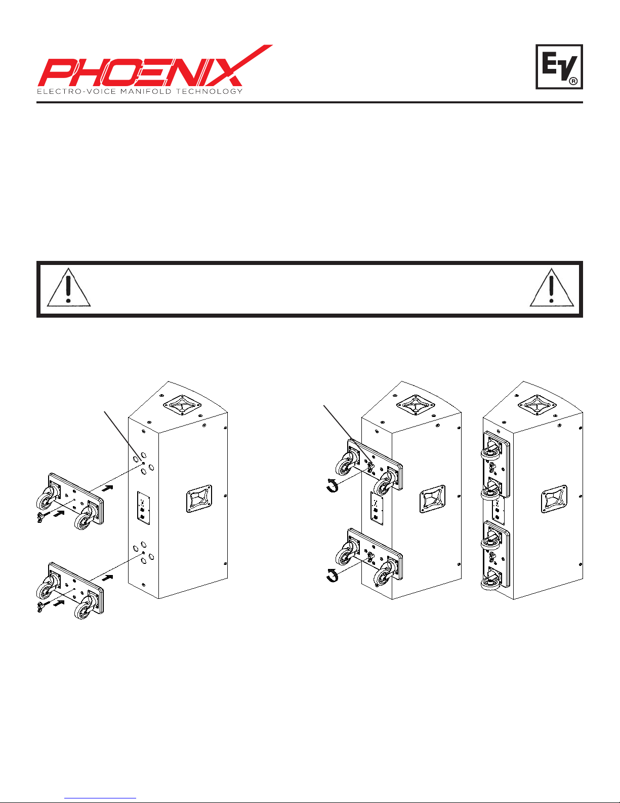
1. Remove (2) 5/16” bolts from rear of the PX2122 or PX2152 enclosure.
2. Align the plastic st andoffs with the recesses in the enclosure so the dolly board is perpendicular to the length of
the enclosure. Turn the wing screw into the enclosure until tight (see Figure 1).
3. When not being used for transport, rotate the dolly boards so they are parallel to the length of the enclosure.
Loosen the wing screw until the dolly board is able to rotate freely . T urn the dolly board 90°, and tighten the wing
screw (see Figure 2).
CAUTION! If the dolly boards are removed, replace the (2) 5/16” bolts into the rear of the
enclosure. If the bolts are not replaced, the speaker will have air leaks resulting in undesirable
performance.
Remove Existing
Screws, Install
Dolly Plates, then
Attach Wing
Screws (2 Places)
Loosen Wing
Screws, Rotate and
Align Grooves, then
Re-attach Wing
Screws
Figure 1:
Assembling the PX-D1 to a Phoenix
PX2122 or PX2152 Loudspeaker
Figure 2:
Rotating the PX-D1 on the rear of a
Phoenix Loudspeaker for shipping or arraying
Page 2
PX-D2
The Electro-Voice® PX-D2 accessory consists of a pair of dolly plates with assembled casters for use with the Phoenix
PX2181 Loudspeaker. The dolly plates double as skid plates for extra protection of the PX2181’s back panel.
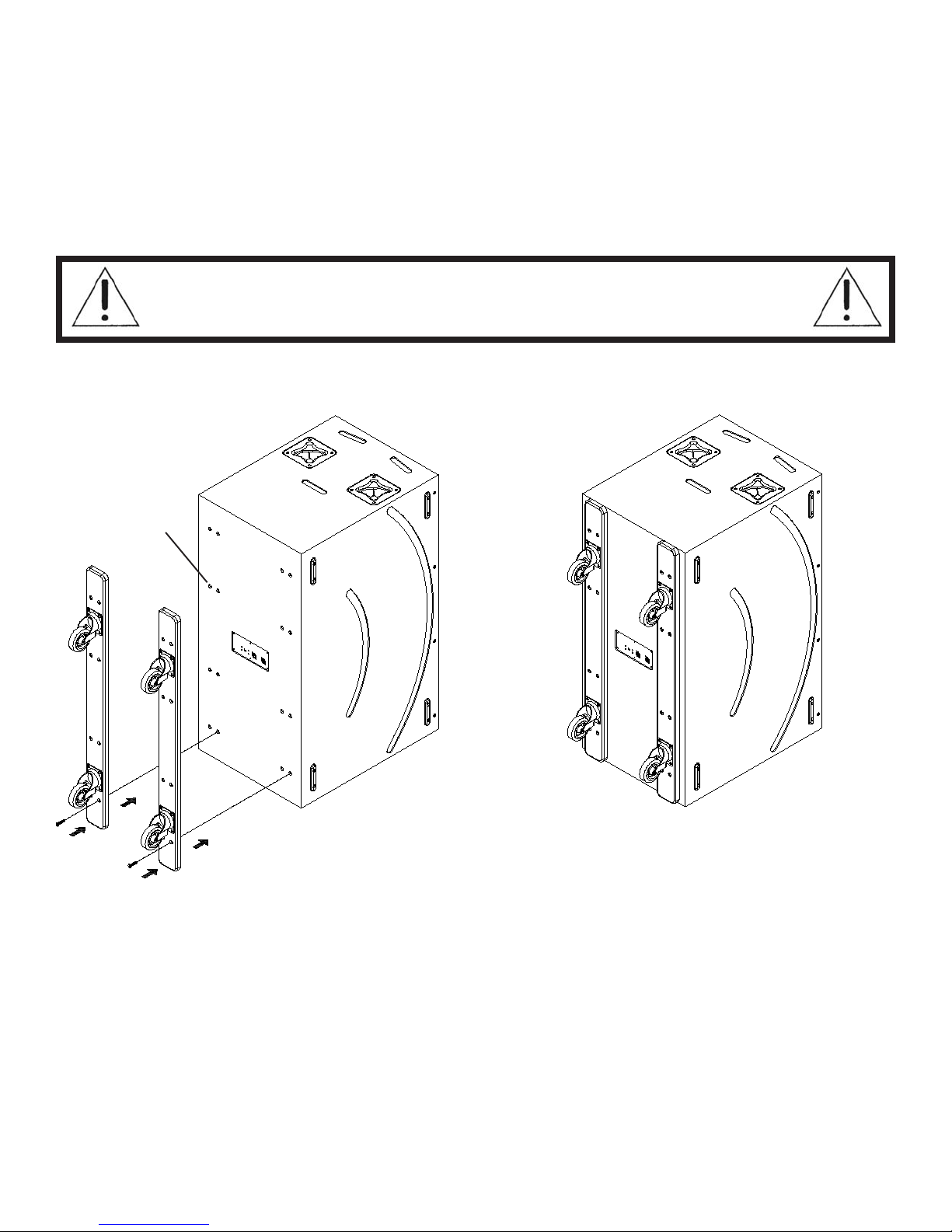
1. Remove (16) 5/16” bolts from rear of the PX2181 enclosure.
2. Align holes in the PX-D2 with the holes on the PX2181 enclosure, and tighten the (16) 5/16” bolts into the dolly
boards (see Figure 3).
CAUTION! If the dolly boards are removed, replace the (16) 5/16” bolts into the rear of the
enclosure. If the bolts are not replaced, the speaker will have air leaks resulting in undesirable
performance.
Remove Existing
Screws, Install
Dolly Plates, then
Re-attach Screws
(16 Places)
Fully Installed
Dolly Plates
Figure 3:
Assembling the PX-D2 to a Phoenix PX2181 Loudspeaker
Page 3
PX-G1
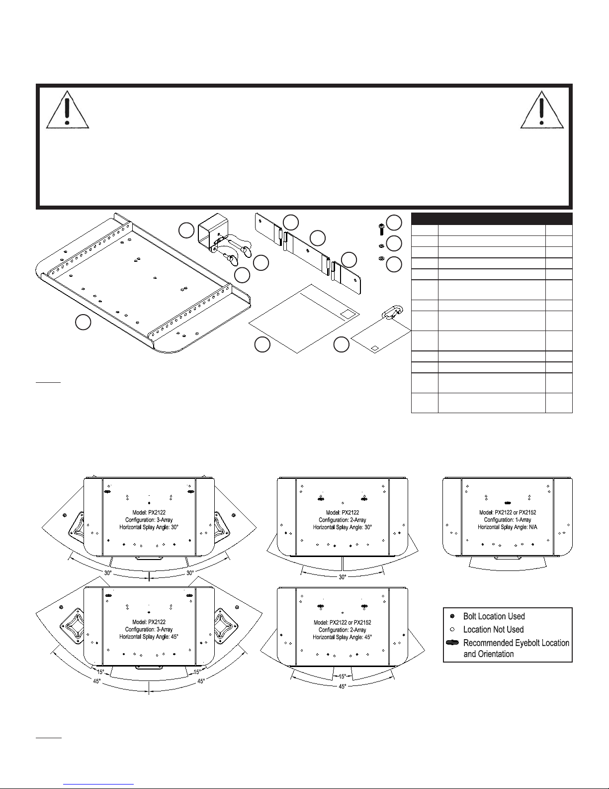
The Electro-Voice® PX-G1 is an array kit that allows for suspension of up to (3) PX2122’s or (2) PX2152’s on a material
lift. There are multiple horizontal splay and vertical tilt options that make the PX-G1 useful in many applications.
CAUTION! Suspending any object is potentially dangerous and should only be attempted by
individuals who have a thorough knowledge of the techniques and regulations of rigging objects
overhead. Electro-Voice® strongly recommends that all speakers be suspended taking into
account all current national, federal, state and local regulations. It is the responsibility of the
installer to ensure that all speakers are safely installed in accordance with all such regulations. When speakers are
suspended, Electro-Voice® strongly recommends that the system be inspected at least once a year. If any sign of
weakness or damage is detected, remedial action should be taken immediately . The user is responsible for making sure
that the grid, and any additional hardware used, is capable of supporting the loudspeaker array. Any hardware used to
suspend a loudspeaker array that is not provided by/associated with Electro-Voice® is the responsibility of others.
tsiLstraP1G-XP
x01M,daeHnottuB,wercS
xineohP,snoitcurtsnIresU
dnagaBenohporciM
B
C
E
F
G
H
I
J
D
A
K L
Figure 4:
Note: The fasteners are located in the microphone bag. The mic bag and carabiner
are included with the PX-G1 to store unused fasteners during transport. Remove the
mic bag and carabiner when the array is in use to prevent rattling.
PX-G1 Parts List
metInoitpircseD.ytQ
AtekcarByarrA1
BrotpadAtfiLlairetaM2
C"05.2x"8/3,tneteD,niP2
D"57.0x"8/3,tneteD,niP2
E
niP
FrennI,etalPegniHraeR1
G
niP
H
I01M,kcoLtilpS,rehsaW01
J01M,talF,rehsaW01
K
L
mm53x5.1
seirosseccA
renibaraC
Installation of the PX-G1
1. Arrange the PX2122 or PX2152 loudspeakers on a flat surface to approximately the desired horizontal splay angles,
and remove the M10 flat head screws from the top of each enclosure a hex key (not included). Only remove the
bolts that are called out for the desired configuration (See Figure 5).
oN,retuO,etalPegniHraeR
1
htiW,retuO,etalPegniHraeR
1
01
1
1
Figure 5:
Horizontal Splay Angle Configurations and Supplemental Hole Locations
Note: Use either PX2122 or PX2152 loudspeakers; the models are NOT designed to be used in an array together. DO
NOT use other loudspeaker models other than the PX2122 and PX2152.
Page 4
Installation of the PX-G1 (continued)
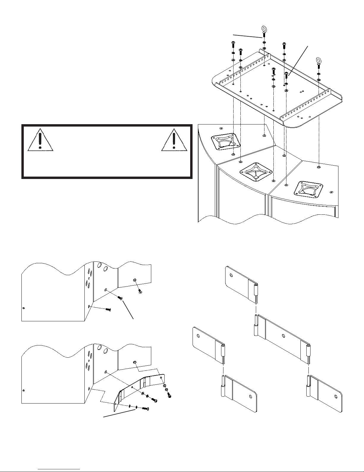
2. Set the array bracket on top of the loudspeakers, and
align the holes on the array bracket with the suspension
points on the loudspeaker. Attach the washers, lock
washers, eyebolts (not included) and M10 button head
screws to the threaded suspension points on the
loudspeakers, using a hex key (not included). Torque all
fasteners down so that the lock washers are fully
compressed. Note final orientation of eyebolts. For
permanent installations, use a thread locker (not
included) on the button head screws and eyebolts (See
Figures 5 and 6).
WARNING! Electro-Voice strongly
recommends that M10 forged
shoulder eyebolts that are compliant
with DIN580 standards are used as
redundant safety points for the array (See Figure 5 for
recommended locations). Eyebolts are not included.
Eyebolt, Lock
Washer , and
Flat Washer
(x2)
Button Head Screw,
Lock Washer , and
Flat Washer (x5)
3. Remove the M10 flat head screws that are located at
the bottom of the enclosure in the rear, and install the
rear hinge plates (See Figure 7). There are different
configurations for the rear hinges depending on how
many enclosures are used (See Figure 8).
Flat Head Screws must be
removed before Plates are
Installed
Figure 6:
Array of Phoenix Loudspeakers
(3 x PX2122, 30° Splay Shown)
Assembling the Array Bracket to an
Button Head Screw, Lock
Washer, and Flat Washer
(One for Each Plate)
Figure 7:
Assembling the Rear Hinge Plates
(3 x PX2122, 30° Splay Shown)
2 Enclosures
(Use both Outer Plates)
Figure 8:
Possible Hinge Plate Configurations
for 2 or 3 Enclosures
3 Enclosures
(Use All Plates)
Page 5
Installation of the PX-G1 (continued)
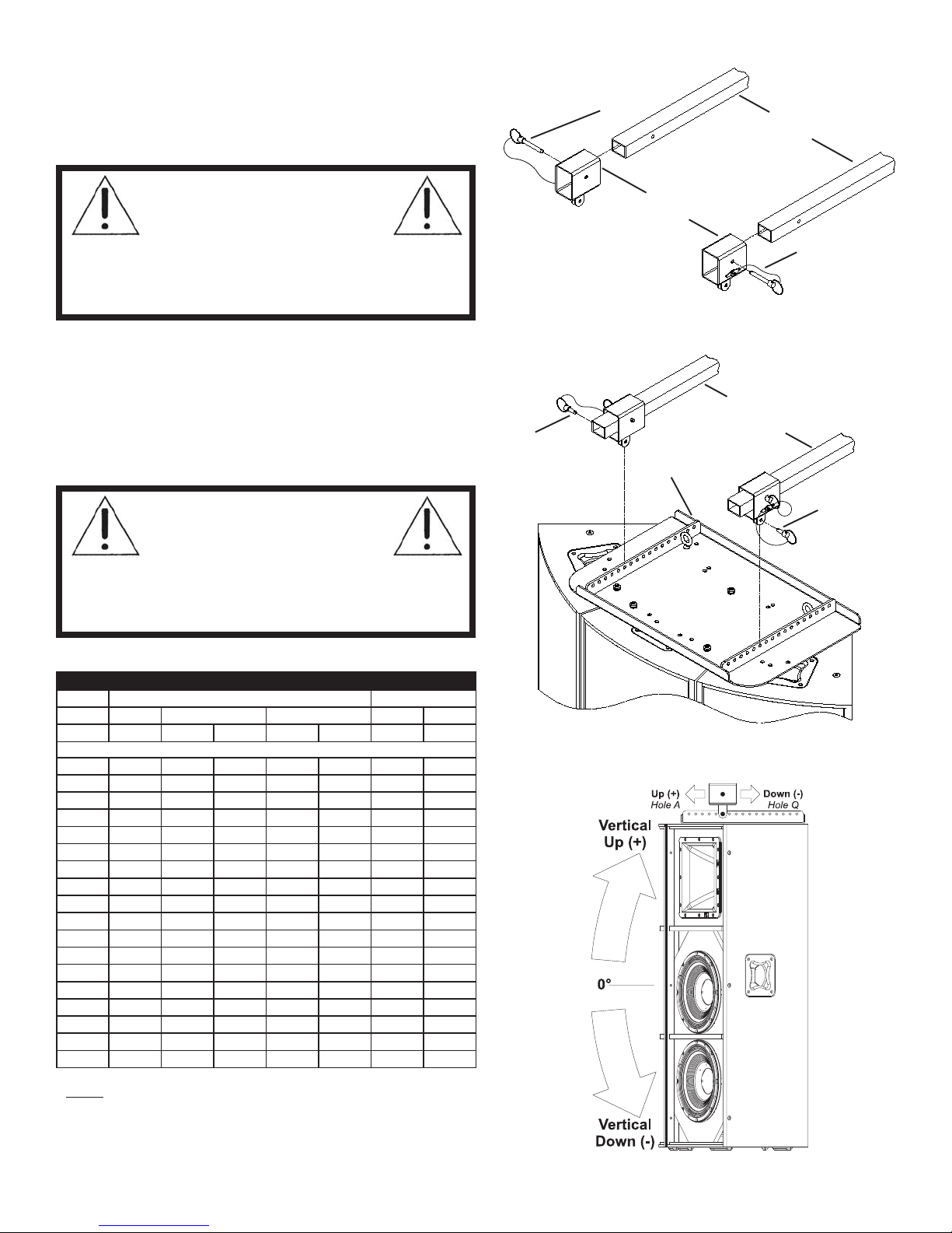
4. Install the material lift adaptors to the material lift by
sliding the tube over the fork, and installing the long
pin through the hole in the fork (See Figure 9).
WARNING! Make sure the pins
for each material lift adaptor
pass through their respective
holes in material lift forks, and
fully lock or engage other side of material lift adaptors.
Do not lift any array without ensuring pins pass through
forks and are fully locked or engaged.
5. Attach the material lift adaptors to the array bracket
using the short pins (See Figure 10). There are 17
holes on the array bracket (A-Q) that can be used
to approximate the desired vertical tilt angle. See
the table below to determine which holes should be
used to achieve the desired tilt angle.
Figure 9:
Short Pin
Long Pin
Material Lift Forks
Material Lift Adaptors
Long Pin
Assembling the Material Lift Adaptors
to Material Lift Forks
Material Lift Forks
and Adaptors
Array
Bracket
WARNING! Make sure the pins
for each material lift adaptor
pass through their respective
holes in array bracket, and fully
lock or engage other side of material lift adaptors. Do
not lift any array without ensuring pins pass through
bracket and are fully locked or engaged.
selgnAtliTlacitreV1G-XP
ledoM2212XP2512XP
gifnoCyarrA-1yarrA-2yarrA-3yarrA-1yarrA-2
°ziroHA/N°03°54°03°54A/N°54
#eloH
A6+8+21+01+21+7+5.11+
B4+6+01+8+01+5+5.9+
C5.1+4+8+6+8+5.2+5.7+
D5.0-2+6+3+6+5.0+5+
E5.2-04+5.1+4+5.1-3+
F5-5.2-2+02+5.3-1+
G7-4-03-06-5.1H9-6-2-5-2-8-5.3-
I11-5.8-5.4-7-5.4-01-5.5-
J31-5.01-5.6-9-5.6-21-5.7K5.51-5.21-9-11-5.8-41-01-
L5.71-51-11-5.31-11-61-5.11M91-71-31-5.51-31-81-5.31N12-91-51-5.71-51-02-5.51O32-12-71-5.91-71-22-5.71P52-5.22-91-5.12-91-42-5.91Q5.62-5.42-12-5.32-12-5.52-5.12-
Figure 10:
Short Pin
Assembling the Array Bracket to the
Material Lift Adaptors
Note: All angles shown in chart are approximate. Cabling
and any other supplementary equipment may change the
absolute angle of the entire array from what is shown in the
chart. Do not attempt to tilt an array beyond the angles
shown in the chart.
Figure 11:
Vertical Tilt Angle Configurations
Page 6
Installation of the PX-G1 (continued)
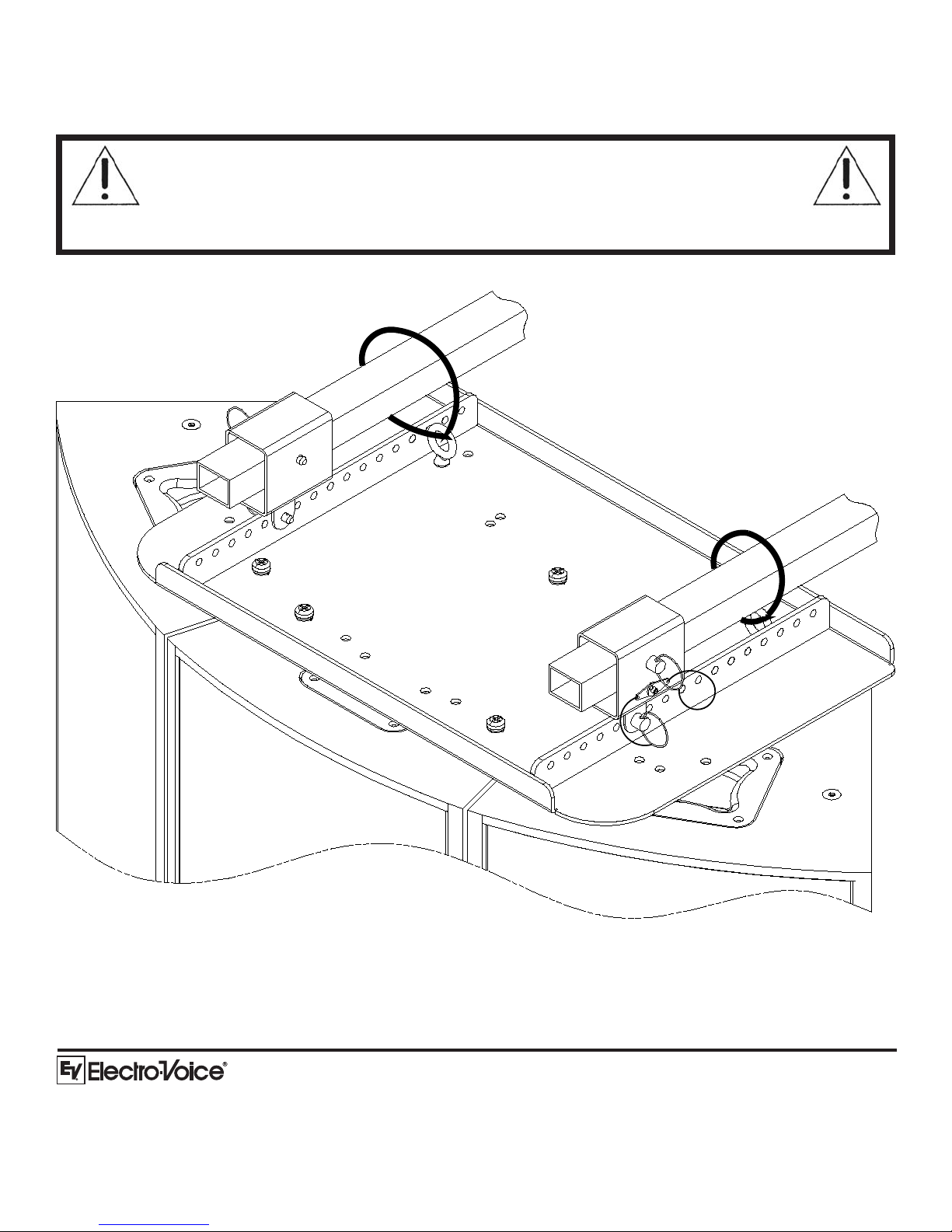
6. Following safe rigging practices, attach rated safety cabling (not included) from the material lift to the eyebolts
(See Figure 12).
WARNING! The center of gravity of the array is located below the hole on the material lift
forks. Never exceed the load limits or the maximum load height that is specified by the
material lift manufacturer. Always place the material lift on a flat, stable surface and use all
stabilizer hardware. Take extra caution when used in windy, outdoor applications that could
cause the array to become unstable. Consult the material lift user manual for proper use and safety guidelines.
Figure 12:
12000 Portland Avenue South, Burnsville, MN 55337
Phone: 952/884-4051, Fax: 952/884-0043
www.electrovoice.com
© Telex Communications, Inc. 8/2007
Part Number LIT000059 Rev A
Attaching Safety Cable through Eyebolts
Europe, Africa and Middle East only. For customer orders,
For warranty information, contact the Service Repair department at:
For technical assistance, contact Technical Support at:
U.S.A. and Canada only. For customer orders,
contact the Customer Service department at
800/392-3497 Fax: 800/955-6831
contact the Customer Service department at
49 9421-706 0 Fax: 49 9421-706 265
616/695-6831 or 800/685-2606
Specifications subject to change without notice.
866/78AUDIO
 Loading...