

Page 1
PIM-122
(standard configuration)
12-Inch, Two-Way System
for Permanent Installation,
Horn-Loaded HF
• Part of PI Matrix SeriesTM—compact
trapezoidal systems for permanent
installation
• Components and physical characteristics
optional, to meet many acoustic, architectural and mechanical requirements
• 50-Hz low end for speech and many music
applications
• Three HF coverages—60° x 40°, 60° x 60°
or 90° x 40° (standard)
TM
• PRO
• For biamplification (standard); passive
• Integral suspension system for safe and
circuit HF protection
network optional
easy installation
SPECIFICATIONS
Versions Available:
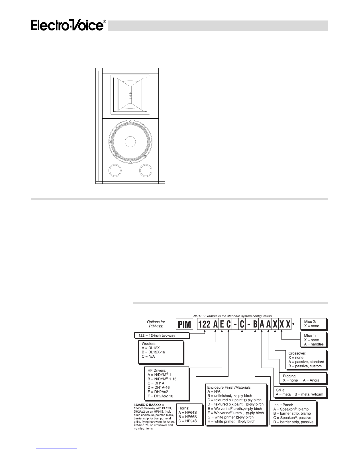
See PIM-122 ordering matrix (Figure 1)
Typical Axial Frequency Response with
Presets of Dx34 Digital Speaker System
Processor (swept sine-wave input,
anechoic environment, 4 volts at 1 kHz
at 10 feet; see Figure 2):
50-18,000 Hz
Typical Axial Frequency Response of
High- and Low-Frequency Sections Alone
(swept sine-wave input, anechoic
environment, 4 volts at 10 feet normalized
for 1 watt at 1 meter; see Figure 3):
50-18,000 Hz
Low-Frequency 3-dB-Down Point:
50 Hz
Usable Low-Frequency Limit
(10-dB-down point):
35 Hz
Recommended Crossover Frequency:
1,200 Hz
Crossover Slopes,
Recommended:
24 dB per octave
Minimum:
12 dB per octave
Long-Term Average Power-Handling
Capacity (see Power-Handling Test
section),
Low Frequency (per EIA RS-426-A 1980):
300 watts
High Frequency (per AES2-1984/ANSI
S4.26-1984):
60 watts
Sensitivity (far-field SPL referred to
1 meter, 1-watt input, anechoic environment, band-limited pink noise),
Low Frequency (100-800 Hz):
95 dB
High Frequency (500-5,000 Hz):
111 dB
SPL at Full Power (far-field SPL at 1 watt/
1 meter referred to full power, anechoic
environment, band-limited pink noise),
Long-Term Average/Peak,
Low Frequency (100-800 Hz):
120 dB/126 dB
High Frequency (500-5,000 Hz):
129 dB/135 dB
Impedance,
Nominal (low frequency/
high frequency):
8 ohms/8 ohms
Minimum (low frequency/
high frequency):
8.0 ohms/5.6 ohms
Average Efficiency,
Low Frequency: 4.5%
High Frequency: 25%
FIGURE 1 — PIM-122 Ordering Matrix
Nominal Coverage Angle,
Horizontal: 90°
Vertical: 40°
Beamwidth (angle included by 6-dB-down
points on polar responses, indicated onethird-octave bands of pink noise, Dx34
presets employed; see Figure 4):
1,250 to 16,000 Hz Horizontal:
90° (+12°, –10°)
3,150 to 16,000 Hz Vertical:
40° (+9, –8°)
Directivity Factor R
Median (see Figure 5):
12.8 (+12.6, –9.9)
Directivity Index Di, 500- to 16,000-Hz
Median (see Figure 5):
11.1 dB (+11.0 dB, –9.9 dB)
(Q), 500- to 16,000-Hz
θθ
θ
θθ
Page 2
PIM-122 SPECIFICATION GRAPHICS
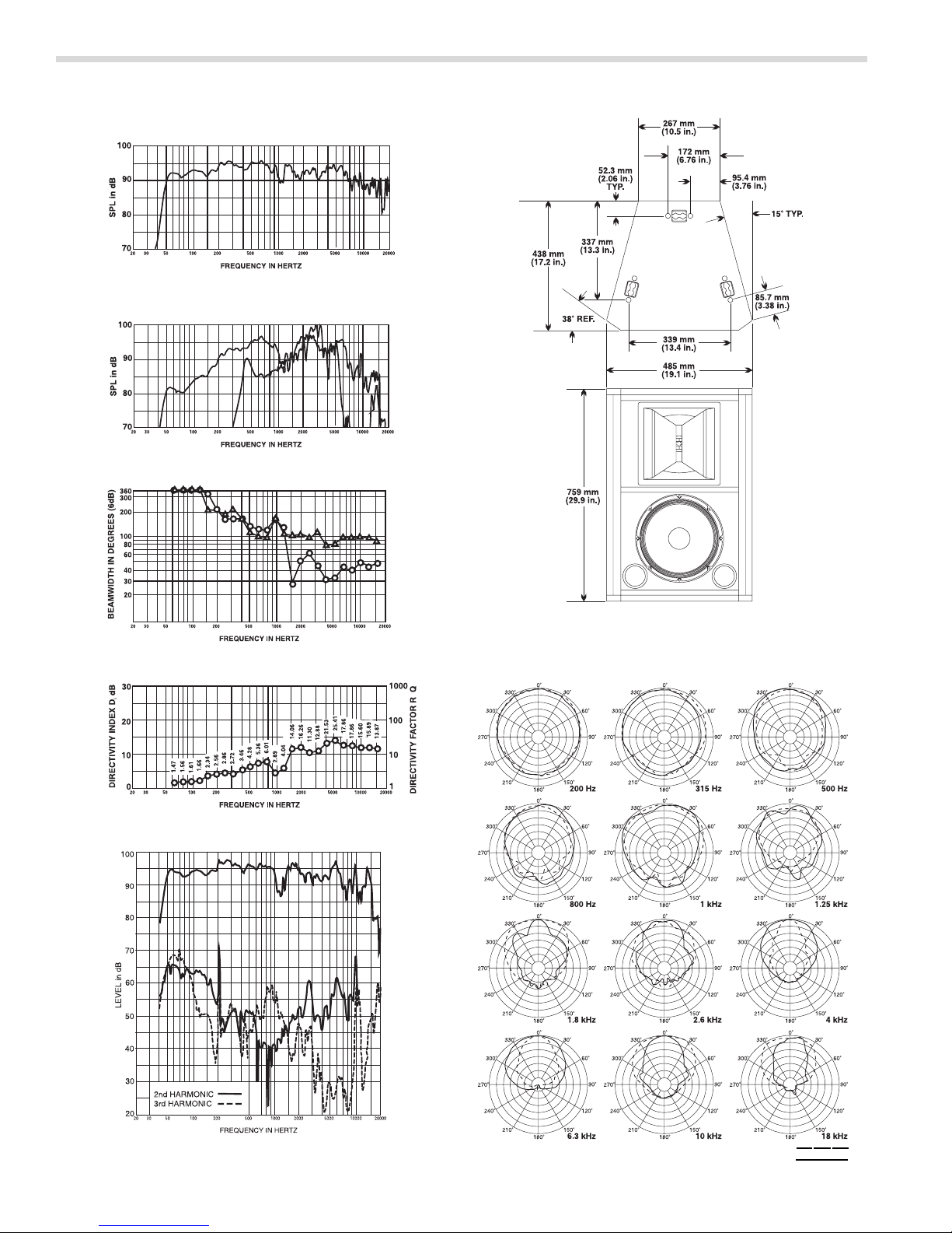
FIGURE 2 — PIM-122 Typical Axial Frequency Response with Presets of
Dx34 Digital Speaker System Processor (swept sine-wave
input, anechoic environment, 4 volts at 1 kHz at 10 feet)
FIGURE 7 — PIM-122 Dimensions
FIGURE 3 — PIM-122 Typical Axial Frequency Response of High- and Low-
Frequency Sections Alone (swept sine-wave input, anechoic
environment, 4 volts at 10 feet normalized for 1 watt at 1 meter)
FIGURE 4 — PIM-122 Beamwidth vs. Frequency (one-third-octave bands of
pink noise)
FIGURE 5 — PIM-122 Directivity Factor and Directivity Index vs. Frequency
(one-third-octave bands of pink noise)
θ
FIGURE 8 — PIM-122 Polar Responses, Selected to Typify Performance
(one-third-octave bands of pink noise)
FIGURE 6 — PIM-122 Harmonic Distortion with Dx34 Presets, 10% Rated
Input Power at 500 Hz (on axis at 1 meter from system)
5 dB PER
DIVISION
HORIZONTAL
VERTICAL
Page 3

Distortion Response with Dx34 Presets,
1% Rated Input Power at 500 Hz (on axis
at 1 meter from system),
Second Harmonic:
100 Hz: <1.0%
1,000 Hz: <1.0%
10,000 Hz: 1.3%
Third Harmonic,
100 Hz: <1.0%
1,000 Hz: <1.0%
10,000 Hz: <1.0%
Distortion Response with Dx34 Presets,
10% Rated Input Power at 500 Hz (on axis
at 1 meter from system; see Figure 6),
Second Harmonic,
100 Hz: 2.5%
1,000 Hz: <1.0%
10,000 Hz: 2.5%
Third Harmonic,
100 Hz: 1.4%
1,000 Hz: <1.0%
10,000 Hz: <1.0%
Transducer Complement,
Low Frequency:
DL12X 305-mm (12-in.) woofer
in a vented enclosure
High Frequency:
HP94S 90° x 40° horn mounted
to DH2As2 compression driver with
51-mm (2-inch) exit
Box Tuning Frequency:
45 Hz
Polarity (all drivers):
A positive voltage applied to the positively
marked input terminal produces a positive
acoustic pressure at the front of the
system
Input Connections, Low Frequency/
High Frequency:
#10 screw terminals on barrier strip; each
driver can be individually accessed
Driver Protection, High Frequency:
Solid-state self-resetting circuit (PRO
TM
circuit) drops input 6 dB; blocking
capacitor with 800-Hz corner frequency
and 6-dB-per-octave slope
Enclosure Materials and Color:
Textured black painted 7-ply void-free
birch
Grille:
Black powder coated, vibration-resistant
steel, removable
Suspension:
Integral three-point flying system (accepts
Ancra 42546-10 single-stud tie-down cargo
fitting; four fittings supplied with system;
see Suspending PIM-122 Enclosures
section)
Dimensions (see Figure 7),
Height:
759 mm (29.9 in.)
Width at front:
485 mm (19.1 In.)
Width at rear:
267 mm (10.5 in.)
Depth:
439 mm (17.3 in.)
Side-Wall Draft Angle:
15°
Net Weight:
35.4 kg (78 Ib)
Shipping Weight:
40.5 kg (89 Ib)
DESCRIPTION AND APPLICATIONS
The Electro-Voice PIM-122 is a compact, trapezoidal two-way speaker system for permanent
installation. The high-frequency section is horn
loaded and the low-frequency section is direct
radiating in an optimally vented enclosure. The
PIM-122 is part of the PI Matrix SeriesTM, a
highly flexible group of full-range and lowfrequency systems for applications where compact systems are appropriate. Many performing arts centers, clubs, auditoriums, sports
facilities and houses of worship are candidates
for the PI Matrix SeriesTM.
The flexibility of the PI Matrix SeriesTM allows
the designer to customize a system to both suit
the acoustic environment and meet a wide
variety of architectural and mechanical requirements. High-frequency horns have been optimally sized to maintain their rated coverage
patterns down to the chosen crossover frequencies and over as wide a frequency range
as possible. Furthermore, the horns are optionally available in three coverage angles (90° x
40°, 60° x 40° and 60° x 60°) to aid in properly
matching a speaker location to the audience
area. In addition, all horns may be rotated about
their axes, for coverage that is independent of
enclosure orientation.
Other PI Matrix SeriesTM options include lowand high-frequency drivers, enclosure materials and finish, grilles, suspension hardware and
input-panel connections, giving the sound contractor or consultant literally thousands of combinations to satisfy the overall system design
criteria.
The PIM-122 standard configuration is a 90° x
40° two-way full-range system for biamplification. The PIM-122 maintains good directivity
control down to 1,500 Hz (see Figure 4). The
low-frequency section incorporates a DL12X
305-mm (12-in.) woofer. The angled enclosure
sides (15°) allow ceiling or under-balcony mounting with a reduced vertical profile and aiming
angle that is inherently in the general direction
of the audience. The enclosure is made of black
painted 7-ply void-free birch and includes certified flying hardware as standard.
Delivering smooth and extended performance,
the high-frequency section operates from 1,200
to 18,000 Hz and consists of a DH2As2 compression driver coupled to an HP94S 90° x 40°
constant-directivity horn. The HP94S horn features integral fiberglass-and-zinc construction
for exceptional strength and performance.
Beamwidth-control vanes in the horn throat
correct all coverage anomalies in the 10- to 20kHz octave. The driver is protected from overdrive by the solid-state, self-resetting PRO
circuit, which drops the input signal by 6 dB.
Additional protection at the low end of the
driver’s range is provided by a series blocking
capacitor with a corner frequency of 800 Hz and
slope of 6 dB per octave.
The low-frequency section operates between
50 and 1,200 Hz and has been designed for
superior performance. The DL12X woofer can
handle very large levels of input power, producing high acoustic output with relatively low
distortion and closely matching the output levels of the high-frequency section.
The PIM-122 is equipped with a number of
additional features to make operation and installation easy and secure. A proprietary structural extrusion is incorporated into the enclosure, providing safe and flexible suspension
(see Suspending PIM-122 Enclosures section).
Up to two enclosures of the same footprint can
be suspended without additional support (as
long as the lower system is not heavier than the
upper system), so arrays can be created quickly
and easily. The grille is composed of vibrationresistant steel for excellent driver protection,
and an optional foam cover can be added for
better protection when used outdoors. Besides
the standard black-painted finish, the enclosure can also be ordered primed in white for
painting with ordinary paints, unfinished for
staining, or with our special Wolverine® weather-
resistant finish for outdoor applications. All drivers on the PIM-122 can be serviced from the
front of the enclosure.
A complete listing of all system options is
shown in Figure 1.
SUSPENDING PIM-122 ENCLOSURES
Suspending any object is potentially dangerous and should be attempted only by individuals who have a thorough knowledge of the
techniques and regulations of hanging overhead. Electro-Voice strongly recommends that
the PIM-122 be suspended taking into account
all current national, federal, state and local
regulations. It is the responsibility of the installer to ensure the PIM-122 is safely installed
in accordance with all such regulations. If the
PIM-122 is suspended, Electro-Voice strongly
recommends that the system be inspected at
least once a year. If any sign of weakness or
damage is detected, remedial action should be
taken immediately.
The PI Matrix Series™ enclosures are suspended using the following approach, which
has been approved by an independent structural engineer. Every enclosure incorporates
six independent suspension points, three on
the top and three on the bottom. A minimum of
three points must be used at all times to suspend the enclosure. The suspension points,
which “tie” the top and sides of the enclosure
together, are made of structural aluminum.
Each suspension point mates to an Ancra
42546-10 locking fitting (four are supplied with
each enclosure ordered with this option, EV
part no. 20562), and each point has a break
strength of 907 kg (2,000 Ib) in any direction.1 A
maximum of two enclosures can be “daisy
chained” together, allowing the construction of
vertical arrays. If longer arrays are required,
provision must be made to independently suspend each enclosure. The Ancra 42546-10
fitting incorporates a safety pin to prevent accidental release, and it should be engaged at all
times.
ROTATING THE HIGH-FREQUENCY HORN
The PIM-122 high-frequency horn may be easily rotated about its major axis, providing coverage independent of enclosure orientation. First
remove the enclosure grille, then the horn. Both
are affixed with Phillips-head screws (use a #2
Phillips screwdriver). Rotate the horn 90° about
TM
its axis and reinstall the components.
CONNECTIONS
The option ordered, biamped or passive crossover with either barrier-strip or Neutrik Speakon® connectors, will determine the wiring of
the system components.
Biamped Input
If the system is biamped with barrier strips,
each frequency section can be individually accessed via #10 screw terminals as marked on
the input panels. If Neutrik Speakon® connectors are used, pins 1+/1– are wired to the lowfrequency driver and pins 2+/2– to the highfrequency section.
Passive Crossover Input
If the passive crossover option is used, both
barrier strips are wired in parallel and pins +1/
–1 on both Neutrik Speakon® connectors are
wired in parallel.
In all cases, drivers are connected with the
same polarity. A positive voltage applied to the
positively marked terminal produces a positive
acoustic pressure at the front of the system.
CROSSOVER, EQ AND SIGNAL DELAY
The PIM-122 is a two-way system which must
be biamped with a separate active crossover. A
_________________
1. For additional information, contact Ancra International at
606/371-7272 or toll free (within U.S. only) at 800/233-5138.
Page 4

1,200-Hz crossover frequency is recommended.
Optimum performance and reliability are provided by 24-dB-per-octave slopes. 12-dB-peroctave slopes are the minimum recommended.
The low-frequency section should have subpassband protection using a high-pass filter set
at about 30 Hz. No signal delay or further EQ is
mandatory but their use can smooth response
and directivity, particularly in the region of crossover. The high-frequency section requires the
appropriate constant-directivity-horn highfrequency boost EQ for flat response.
The Dx34 digital speaker system processor
can be set to provide subpassband protection,
crossover, EQ and signal delay for optimum
performance of the PIM-122. Contact ElectroVoice for the specific parameter settings. Alternatively, the XEQ-2 or XEQ-3 analog crossover/equalizer/delay networks can be used.
High-frequency horn EQ is provided by plug-in
modules, the specific model of which is determined by the horn model. The XEQ engineering
data sheets provide this specific information.
LOW-FREQUENCY ENHANCEMENT
If it is desirable to enhance low-frequency performance, Electro-Voice recommends, depending on installation requirements, the PIM-151 or
PIM-251 PI Matrix SeriesTM systems as well as
any of the TL series or MTL series of Manifold
Technology® systems. Contact Electro-Voice
for information on these systems.
FREQUENCY RESPONSE
PIM-122 axial frequency responses were measured in Electro-Voice’s large anechoic chamber at a distance of 3.0 meters (10 feet) with
swept sine-wave input. Figure 2 shows the
typical overall system response with presets of
the Dx34 digital speaker system processor.
Speaker drive voltage is 4 volts at 1 kHz. Figure
3 shows the responses of the individual lowand high-frequency sections with a 4-volt drive,
normalized for a 1-watt input and a 1-meter
distance.
DIRECTIVITY
The directional characteristics of the PIM-122
were measured in Electro-Voice’s large
anechoic chamber, with a test signal of onethird-octave filtered pink noise at the frequencies indicated. A full spherical measurement
system, which is fully compatible with Mark IV
Audio’s AcoustaCADD™ computer aided design program, was used. All directional information was measured at 6.1 meters (20 feet).
Figure 8 illustrates the nominal horizontal and
vertical polar responses, with the long system
axis vertical. If the high-frequency horn is rotated, then the horizontal and vertical polars
should be interchanged.
Figure 4 illustrates the horizontal and vertical
beamwidths. Beamwidth is the angle at which
the horizontal and vertical polar responses
have decreased in level by 6-dB when compared to the on-axis frequency response.
Figure 5 represents the total directivity of the
PIM-122. The directivity factor Rθ (Q) is the
relative value, at a point, when compared to an
ideal spherical response. The directivity index
(Di) is calculated by Di = 10log10R.
SERVICE
In the unlikely event the PIM-122 requires service, each driver can be replaced or serviced
from the front. A service data sheet is available
from Electro-Voice.
POWER-HANDLING TEST
Electro-Voice components and systems are
manufactured to exacting standards, ensuring
they will hold up, not only through the most
rigorous of power tests, but also through continued use in arduous, real-life conditions. Two
main test specifications are used: the AES
Recommended Practice for Specification of
Loudspeaker Components Used in Professional
Audio and Sound Reinforcement (AES2-1984 /
ANSI S4.26-1984) and the EIA Loudspeaker
Power Rating Full Range (ANSI / EIA RS426-A
1980). Both of these specifications use random-noise spectrum which mimic typical music
and test the thermal and mechanical capabilities of the components. Electro-Voice will support relevant additional standards as and when
they become available. Extreme, in-house
power tests, which push the performance boundaries of the components, are also performed
and passed to ensure years of trouble free
service.
Specifically, the PIM-122 high-frequency section passes AES2-1984/ANSI S4.26-1984 with
the following values:
Z
= 5.6 ohms at 7,000 Hz
min
P
= 60 watts
E(max)
Test voltage = 18.3 volts rms
36.7 volts peak (+6 dB)
Selected decade = 1,500-15,000 Hz
The PIM-122 low-frequency passes ANSI/EIA
RS-426-A 1980 with the following values:
RSR = 6.9 ohms (1.15 x RE)
P
= 300 Watts
E(max)
Test voltage = 45.5 volts rms
91.0 volts peak (+6 dB)
ARCHITECTS’ AND ENGINEERS’
SPECIFICATIONS
The loudspeaker shall be a two-way system for
biamplification. Low frequencies shall be reproduced by an 8-ohm 305-mm (12-in.) woofer
with an edge-wound flat-wire 63.5-mm (2.5-in.)
voice coil capable of handling 300 watts long
term per ANSI/EIA RS-426-A and with a sensitivity of 95 dB 1 watt/1 meter. High frequencies
shall be reproduced by an 8-ohm compression
driver with a 76.2-mm (3-in.) diaphragm and a
51-mm (2-in.) exit, capable of handling 60 watts
long term per AES2-1984/ANSI S4.26-1984,
coupled to a constant-directivity horn with a 90°
x 40° coverage pattern and with a sensitivity of
112 dB. The high-frequency horn shall be rotatable 90° about its axis within the enclosure. The
system shall reproduce frequencies from 50 to
18,000 Hz and have a nominal coverage pattern of 90° x 40°, with directivity control maintained down to 1,500 Hz. The recommended
crossover frequency shall be 1,200 Hz. Maximum average sound pressure levels at 1 meter
shall be 120 dB (low-frequency section) and
129 dB (high-frequency section), with shortterm peaks 6 dB higher.
The enclosure shall be constructed of 7-ply
void-free birch and finished in black textured
paint. The enclosure shall have a trapezoidal
footprint. Dimensions shall be 759 mm (29.9
in.) high, 485 mm (19.1 in.) wide at the front, 267
mm (10.5 in.) wide at the rear and 438 mm (17.3
in.) deep. Enclosure sides shall have a 15° draft
angle. The enclosure shall have a suspension
system approved by an independent structural
engineer and consisting of three independent
suspension points on the top and three on the
bottom, all of which shall mate with Ancra
42546-10 fittings. Net weight shall be 35.4 kg
(78 lb).
The loudspeaker system shall be the ElectroVoice PIM-122.
Note: the PIM-122 described above is the
standard configuration. Acoustic and mechanical details will vary when different options are supplied.
UNIFORM LIMITED WARRANTY
Electro-Voice products are guaranteed against
malfunction due to defects in materials or workmanship for a specified period, as noted in the
individual product-line statement(s) below, or in
the individual product data sheet or owner’s manual,
beginning with the date of original purchase. If
such malfunction occurs during the specified period, the product will be repaired or replaced (at our
option) without charge. The product will be returned to the customer prepaid. Exclusions and
Limitations: The Limited Warranty does not apply
to: (a) exterior finish or appearance; (b) certain
specific items described in the individual productline statement(s) below, or in the individual product data sheet or owner’s manual; (c) malfunction
resulting from use or operation of the product other
than as specified in the product data sheet or
owner’s manual; (d) malfunction resulting from
misuse or abuse of the product; or (e) malfunction
occurring at any time after repairs have been made
to the product by anyone other than Electro-Voice
or any of its authorized service representatives.
Obtaining Warranty Service: To obtain warranty
service, a customer must deliver the product,
prepaid, to Electro-Voice or any of its authorized
service representatives together with proof of purchase of the product in the form of a bill of sale or
receipted invoice. A list of authorized service representatives is available from Electro-Voice at 600
Cecil Street, Buchanan, MI 49107 (616/695-6831
or 800/234-6831). Incidental and Consequen-
tial Damages Excluded: Product repair or replacement and return to the customer are the only
remedies provided to the customer. Electro-Voice
shall not be liable for any incidental or consequential damages including, without limitation, injury to
persons or property or loss of use. Some states do
not allow the exclusion or limitation of incidental or
consequential damages so the above limitation or
exclusion may not apply to you. Other Rights:
This warranty gives you specific legal rights, and
you may also have other rights which vary from
state to state.
Electro-Voice Speakers and Speaker Systems
are guaranteed against malfunction due to defects
in materials or workmanship for a period of five (5)
years from the date of original purchase. The
Limited Warranty does not apply to burned voice
coils or malfunctions such as cone and/or coil
damage resulting from improperly designed enclosures. Electro-Voice active electronics associated with the speaker systems are guaranteed for
three (3) years from the date of original purchase.
Additional details are included in the Uniform
Limited Warranty statement.
Electro-Voice Flying Hardware (including enclosure-mounted hardware and rigging accessories)
is guaranteed against malfunction due to defects
in materials or workmanship for a period of one (1)
year from the date of original purchase. Additional
details are included in the Uniform Limited Warranty statement.
Electro-Voice Accessories are guaranteed
against malfunction due to defects in materials or
workmanship for a period of one (1) year from the
date of original purchase. Additional details are
included in the Uniform Limited Warranty statement.
Service and repair address for this product: ElectroVoice, Inc., 600 Cecil Street, Buchanan, Michigan
49107 (616/695-6831 or 800/234-6831).
Specifications subject to change without notice.
ELECTRO-VOICE
MANUFACTURING PLANTS AT BUCHANAN, MI NEWPORT, TN SEVIERVILLE, TN OKLAHOMA CITY, OK GANANOQUE, ONT.
© Electro-Voice, Inc. 1995
Litho in U.S.A. Part Number 532701 — 9528
a MARK IV company
600 Cecil Street, Buchanan, Michigan 49107
 Loading...