

Page 1
SPECIFICATIONS
Frequency Response:
800-5,000
(see Figure
Power Handling,
8
Hours, 6-dB Crest Factor:
25 watts
Impedance:
16 ohms
Sound Pressure Level at
Input Average, Pink Noise Band
from
104
Horizontal Beamwidth:
82O @ 2 kHz (see Figure
Vertical Beamwidth:
82O @ 2 kHz (see Figure 2)
Directivity Factor
10.25 @ 2 kHz
Usable Low-Frequency Limit:
600 Hz
Construction:
Rugged die
transformer housing. Diaphragm is
phenolic impregnated linen
speaker parts are of anodized aluminum
with baked
entrance is provided on the bottom side
Voice
5.1 cm (2.0 in.)
Magnet Weight:
0.93
Magnet Material:
Alnico
Dimensions,
Height:
25.4 cm (10.0 in.)
Width:
16.4 cm (6.4 in.)
Depth:
1
Net Weight:
4.0
Shipping Weight:
4.5
HZ
f
5
dB
3)
(500-5,000
800-5,000
dB
-
Coil Diameter:
kg (2.1 Ib) with plates
1.3
kg
kg
Hz:
R,
(a):
-
cast aluminum case and
-
on acrylic paint. A cable
V
cm (4.4 in.)
(8.8
Ib)
(10.0
Ib)
Hz
pink noise)
1
Meter, 1 Watt
-
Limited
2)
-
base. All metal
DESCRIPTION
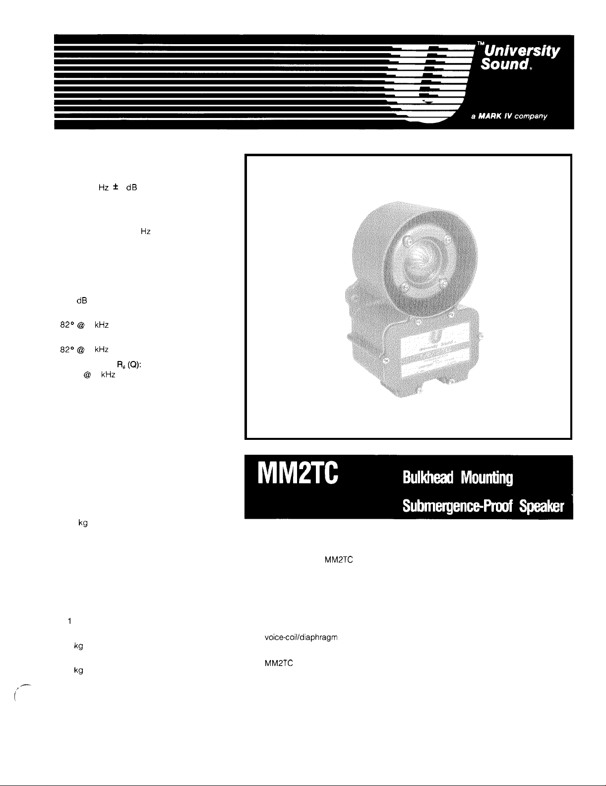
The University Sound MM2TC is aconservatively rated 25-watt "submergence-proof'' speaker
designed for wall, ceiling, or bulkhead mounting.
-
The driver employs a diaphragm with a phenolic impregnated linen
with
"W"
shaped Alnico V magnet structure.
Provisions are made in the housing for installation
University Sound model
The voice-coil/diaphragm assembly is protected by a special anit-fungicide treatment and
easily accessible for cleaning by removal of the die-cast reflector on the front of the speaker.
MM2TC
is
The
gases.
self-draining and designed
It
is built
to
5030
(30
W).
penetrate high noise levels in boiler rooms, mines, railroads, etc.
of
a matching transformer such as the
to
withstand fungus, dust, salt spray, live steam, and
base and 2.0-inch voice coil
is
Page 2
Page 3

The
bell,
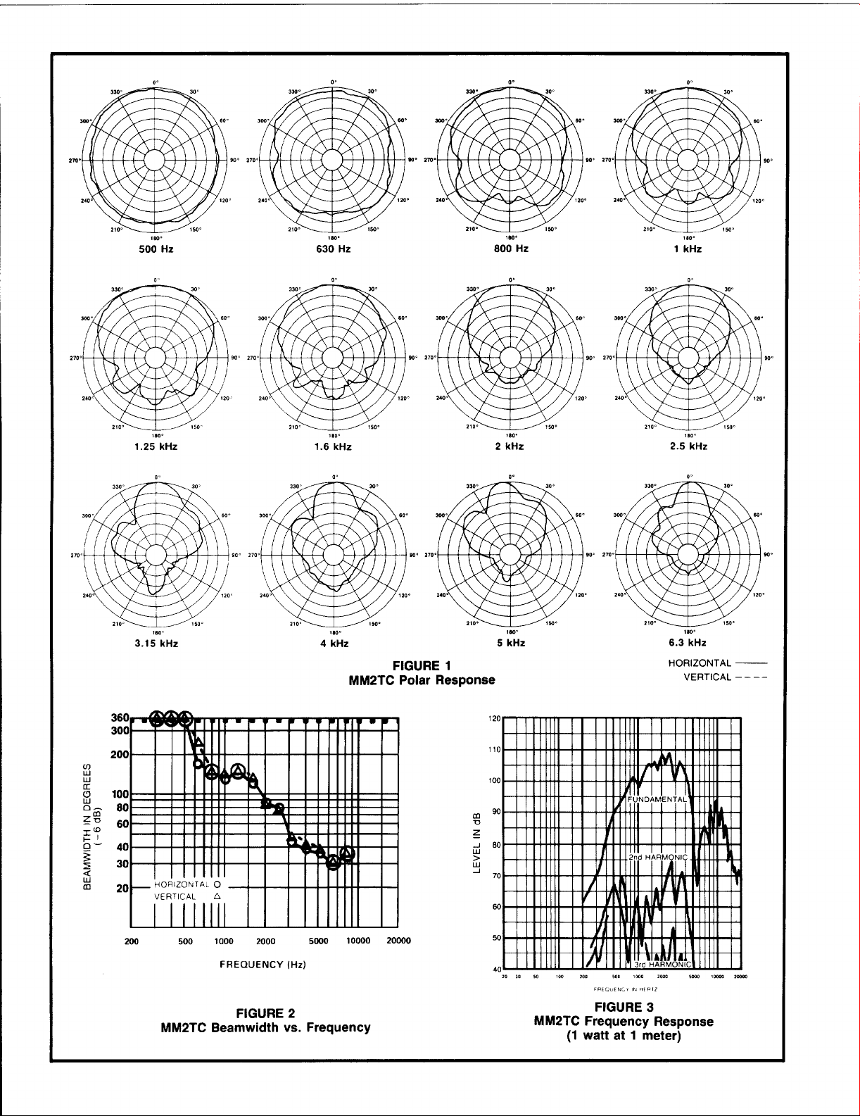
DIRECTIONAL PERFORMANCE
The directional characteristics of the MM2TC
were measured by running a set of polar
_
responses in University’s large anechoic
-
chamber. The test signal was
band-limited pseudo-random pink noise
centered at the
indicated in Figure 1
Additional typical data
Figure
2
beamwidth versus frequency for an MM2TC.
IS0
standard frequencies
is
which indicates 6-dB-down
provided in
%-octave-
FREQUENCY RESPONSE
Figure 3 shows the axial frequency response
of the
MM2TC.
distance of
wave.
It
was measured at a
1
meter, using a swept sine
INSTALLATION
Mounting of the MM2TC is by way of two
13/32’’
holes spaced 5.688” on centers.
A
cable entrance threaded for l/z”-14 I.P.S.
pipe or rigid conduit is provided in the bot
tom side of its cork-neoprene gasketed
transformer housing.
transformer housing shall be die
aluminum and designed
be
ing of diaphragm. Voice-coilldiaphragm
assembly shall be protected by special anti
fungicide treatment.
Transformer housing shall be provided for
installation of line
exceed
in.), by 7.0
diameter holes shall be provided for moun
ting purposes.
Dimensions shall be 25.4 cm (10.0 in.) high,
by 16.4 cm (6.4 in.) wide, by 11.3 cm (4.4
in.) deep. Net weight shall not exceed
(8.8 Ib). The loudspeaker shall be the
University Sound
-
reflector, and weatherproof
removed for easy accessibility and clean
-
5.8
matching transformer not
cm (2.25 in.), by 5.8 cm (2.25
cm (2.75 in.). Two 13/32-inch
MM2TC.
-
cast
so
that reflector can
4.0
WARRANTY
Speakers and Speaker Systems (excluding
active electronics) are guaranteed for five
-
years from date of original purchase against
malfunction due
-
and materials.
unit will be repaired or replaced (at our
option) without charge for materials or labor
if delivered prepaid to University Sound. Unit
to
will be returned prepaid. Warranty does not
extend
coils, or malfunction due
-
tion under other than specified conditions,
including cone
from improperly designed enclosures, nor
does it extend
damages. Some states do not allow the
kg
exclusion or limitation of incidental or
consequential damages,
sion may not apply
than University Sound will void this
guarantee. This warranty gives you specific
legal rights, and you may also have other
rights which vary from state
Service and repair information for this
product: University Sound,
Phone 818l362-9516. FAX 8181367-5292
(Limited)
If
to
finish, appearance items, burned
to
-
University Sound
to
defects in workmanship
such malfunction occurs,
to
andlor coil damage resulting
incidental or consequential
so
to
you. Repair by other
abuse or opera
the above exclu
to
state.
Inc.,
-
-
LOW-FREQUENCY DRIVER PROTECTION
When frequencies below the low-frequency
cutoff for the horn assembly are fed
driver, excessive current may be drawn the
by driver. For protection
and transformer (if driver with built
transformer is used),
with driver, or transformer primary are
recommended.
of
driver, amplifier,
capacitor(s) in series
to
the
-
in
Applications and technical information for
University Sound products:
University Sound, Inc., Technical
Coordinator, Phone
FAX 81
813673292,
Specifications subject
without notice.
8181362-951 6,
to
change
For drivers without transformers:
16-0hm driver, 25
150
V
dc or 150 V non-polarized electrolytic,
or two 150
required value in series, back
70
-
volt lines.
V
V
-
50
mf
dc electrolytics of two times
ARCHITECTS’ AND ENGINEERS’
SPECIFICATIONS
The loudspeaker shall be integral driver and
submergence
impregnated linen
rugged two
The axial frequency response will extend
from 800
exhibit
Sound pressure level will be 104 dB
(1
Wl1 M) with an 800
noise signal applied. Dispersion shall be
at 2 kHz.
I
-
proof speaker with a phenolic
-
base diaphragm and
-
inch voice coil.
to
5,000
Hz
and the horn shall
a
low-frequency cutoff of
to
5,000
to
back, for
600
Hz
Hz.
pink
82O
Page 4

BASIC GUIDELINES
FOR
THE USE
OF
HORNS AND DRIVERS WITHIN A SOUND SYSTEM.
DESIGNING
The Basic
Many sound systems would have better performance
principles are kept in mind Speakers
should bechosen, aimed and powered
highly absorbtive audience, with no sound aimed at the reflective wall and ceil
ing surfaces Where multiple speakers are required in order
uniformdirect field, their coverage patterns should beonlyslightly overlapped,
so
that each section of the audience is covered by a single speaker To the
extent this ideal is achieved reverberation is minimized and intelligibility is
maximized
The following
two design approaches
What is Reverberation?
Reverberation is the persistence of sound within an enclosure, such asa room,
after the original sound has ceased Reverberation may also be considered
as aseries of multiple echoes
a single continuous sound These echoes decrease in level with successive
reflections, and eventually are completely absorbed by the room
-
Non
An open, outdoor space is considered
as virtually all sound escapes the area without reflection.
Variations in Level Due to Distance for Non
In non
be reduced by half
(this is called the inverse
expected as distance from the speaker is increased from the one
(3 28
Reverberant Environments
Wheresound is reflectedfrom
which the
higher and more constant than predicted by using the inverse
alone
Variations in Level Due
The reverberant field will begin
feet This distance is greatest for the least reverberant rooms and speakers
with narrow beamwidth angles The frequency and beamwidth
provided by the datasheet are still required
of
the direct sound (or direct field) from the loudspeaker(s) which still follows
the inverse square law
intelligibility This is why the sound system designer should seek a uniform
directfield, with
a single speaker with awide beamwidth angle used
reverberant room The direct field will be
the
backof the room that speech will probably be unintelligible
Calculating Variations in Level Due
Each time the power delivered
dropof3dBoccurs Thenomographof
to
be expected as the power varies from the one-watt input typically used in
SPL specifications
Power Handling
The power rating of a speaker must be known
is capable of meeting the sound pressure level requirements of the system
The power rating combined with the sensitivity will enable a system designer
to calculate the maximum sound pressure level attainable at a given distance
FOR
INTELLIGIBILITY AND ADEQUATE SPL
Idea
if
the following basic
with the appropriatecoverage patterns
to
achievea uniform direct field in the
to
achieve a
material explains these concepts in more detail and illustrates
so
closely spaced in time that they merge into
Reverberant Environments
-
reverberant environments, such as outdoors, sound pressure level will
-
foot) measuring distance typically used in SPL specifications.
(6
dB) every time the distance form thespeaker is doubled
-
square law). Figure A shows the dB losses
"
reverberant field" dominates and the sound pressure level is
aslittle reverberantfieldas possible For example, consider
wallsand other surfaces, thereisapoint beyond
to
Distance for Reverberant Environments
It
is the direct signal that contributes
to
be a non-reverberant environment,
-
Reverberant Environments
-
-
square law
todominatetypicallyatdistancesof
to
obtain satisfactory distribution
to
so
far below the reverberant field at
to
to
Changes in Electrical Power
the speaker is reduced by one-half, a level
FigureBshowsthethechangein
cover a long, narrow
to
determine whethera design
10to30
speckations
to
speech
to
meter
be
dB
DISTANCE
FROM
CHANGE
SPEAKE:IH;
-
Powering to Achieve Both Average and Peak SPL
The average power that must be delivered
desired average SPL can be determined from the previously presented
material on speaker sensitivity, level variation with distance and level varia
tion with power. Enough additional power must be available
without distortion the short
Thisdifference between the
when expressed in
or "headroom." The peaks can be large, as noted earlier: at least
the average
The better sound systemsare designed for peaks that are
average, although
voice paging systems The
requiredfor theaveragesound levels The 6
power.
Utilizing Speaker Beamwidth Information for Maximum Intelligibility
Knowing the beamwidth angle
direct field in the listening area After selecting a desired speaker location, the
beamwidth angle needed
over
to
known the correct speaker can be found by using catalog specifications
Using Easy
In some circumstances
than using the basic horizontal and vertical beamwidth angles Environments
which have excessive reverberation or high ambient noise levels make
especially difficult
In recent years a number of computer based techniques have been
developed
systems use personal computers with relatively sophisticated graphics
Simpler systems, such as Electro Voice
Program) utilize clear overlays and require programmable scientific
calculators However, the
to
utilizeeven thesimpler systems are not attractivetosomesound systems
designers Because of this University Sound has developed a special
adaptation of VAMP, called Easy VAMP
aid without the complexity and cost of the VAMP programs
More information
found in the University Sound Guide
M
lmm
::$a
FIGURE
Level Variation Level Variation
With Distance
(1
0
dB).
the walls or ceilings must be determined Once these angles are
-
VAMP
to
help sound system designers Some of the more complex
IN
4
(dB)
M
A
to
the speaker@)
-
term peaks that exist in voice and music program.
peakand averagecapability of a sound system,
dB, is often called "peak-to-average ratio,
6
dB of headroom is sufficient for most general-purpose
1
0-dB peaks require amplifier power ten times that
-
dB peaks require fourtimesthe
of
a loudspeaker can aid in providing a unlorm
to
adequately cover the listeners without spilling
TM
and Floor-Plan Isobars
d
is desirable
to
achieve the desired
hardwareisoftware and training investment required
on
both the Easy VAMP
to
use an approach that is more detailed
SPL
and intelligibility
TM
s
VAMP
TM
which providesa similar design
TM
and floor plan isobars can be
f25
M
3+m
FIGURE B
With Power
to
to
" "
10
dB above the
(Very Accurate Mapping
achieve the
reproduce
crest factor
10
times
-
"
it
Part Number
US 42-02-
Litho
in
0261
U.S.A
531291-923
17
 Loading...