

Key Features:
• Accepts Electro-Voice & Telex bodypack
transmitters. (See page 3 for details.)
• Selectable polar pattern to easily adapt
to different acoustic environments.
Choose between omni, cardioid,
supercardioid or figure 8.
• Exceptional sound quality with EV’s
proven PolarChoice design.
• Consistent microphone voicing across
all four patterns.
• Easy to use mute switch. Can be
programmed to operate as either latching
on/off or momentary push-to-mute /
push-to-talk
• High visibility blue LED clearly displays
mic status to the user.
• High visibility blue LED clearly displays
mic status to the user.
• Wireless system sold separately.
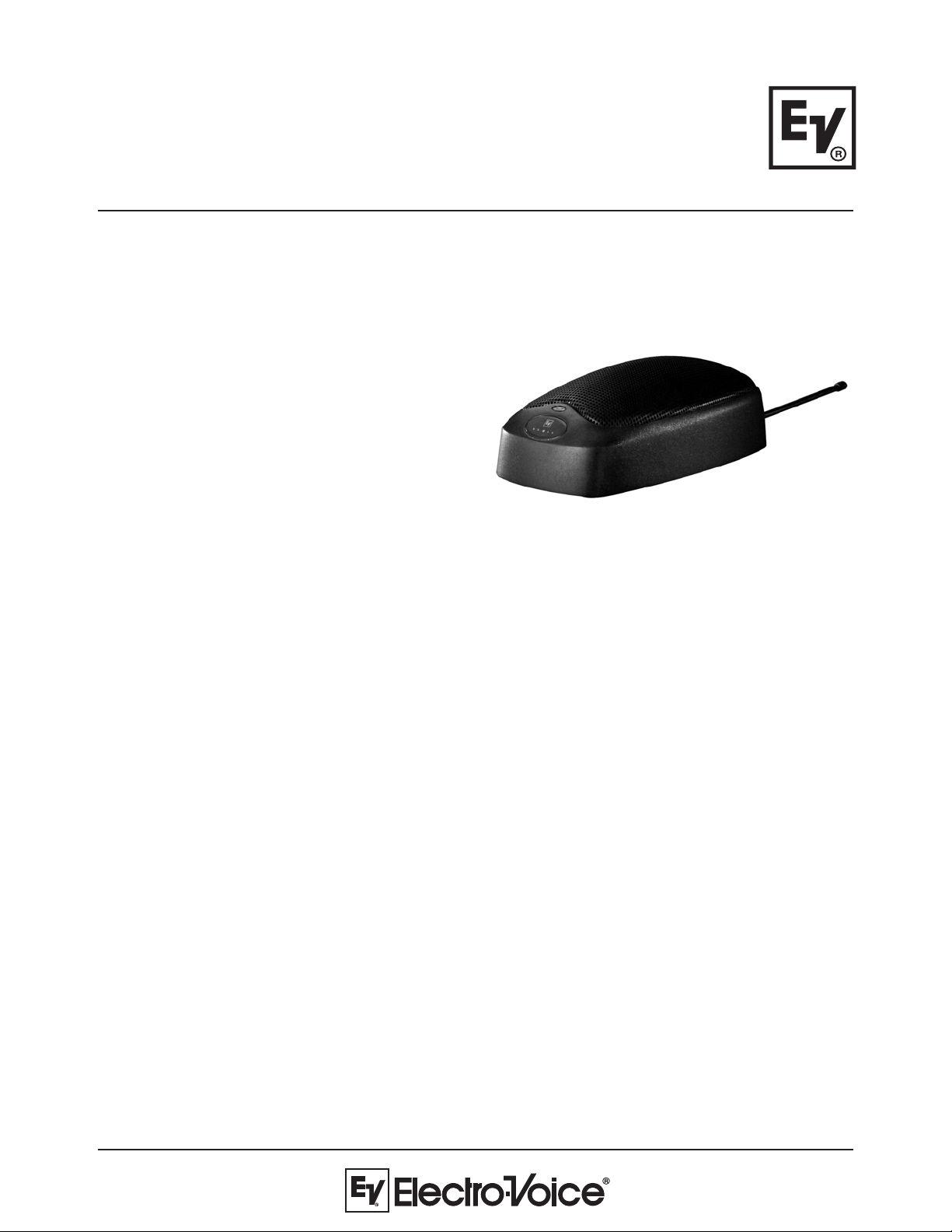
P olarChoice
Boundary
Satellite
Multi-Pattern Wireless
Boundary Microphone
General Description:
The PolarChoice™ Boundary Satellite is a low profile multi-pattern microphone. This low-profile foundation hides
PolarChoice™ Boundary Satellite’s most powerful feature – space for a wireless transmitter . T urn the microphone over to reveal the specially designed compartment for housing an Electro-V oice or T elex bodyp ack
transmitter. Connect the microphone to the bodypack, set-up the wireless channel, and place the
PolarChoice™ Boundary Satellite anywhere an easy-to-use microphone is required. No longer do you have to
cut holes in tables, run long cables, or compromise the architectural integrity of an installation. With the
PolarChoice™ Boundary Satellite, anything is possible.
The Boundary Satellite features an EV PolarChoice™ multi-pattern microphone. The multi-pattern versatility of
the PolarChoice™ microphone makes it a true “problem solver”. With one non-directional and three directional
polar patterns available, the PolarChoice™ microphone is ideal for virtually any installation. Of particular interest
is the figure 8 pattern that allows miking people on opposite sides of a table with only one mic, while providing
dramatic reduction of ambient room noise.
The PolarChoice™ Boundary Satellite is designed to take acoustic advantage of placing a microphone close to
a “boundary” such as conference table. Advant ages include reduced phase cancellation and up to 3dB reduction
in ambient noise.
The PolarChoice™ Boundary Satellite also includes a switchable high pass filter and high-performance vibration
damping pads on the bottom to greatly reduce any vibration induced noise pick-up.
PolarChoice Boundary Satellite
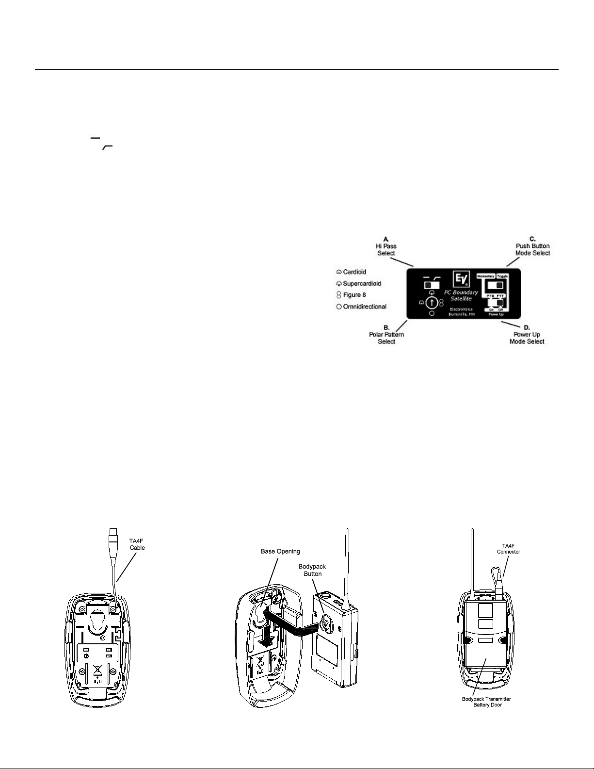
PolarChoice Boundary Satellite Controls:
Switch “A” – Hi Pass Select:
Start with this switch set to the left (flat response). If the mic is in a location where low frequency rumble or wind noise is encountered, moving
this switch to the right will help by reducing low frequency sensitivity.
Switch “B” - Polar Pattern Select:
The cardioid polar pattern works well for most installations. If feedback from a sound system occurs, switching to the supercardioid pattern will
usually allow increased mic gain before feedback. The figure 8 pattern can be used to mic two people sitting on opposite sides of a table,
potentially reducing the total number of mics required. The omnidirectional pattern is best suited for situations where there is no sound
reinforcement system present, such as for recording.
Switches “C” and “D”:
Together control the actions of the push-button switch power-up state.
NOTE: The blue light on the front of the mic is lighted whenever the microphone
audio is active.
Flat ( ): Normal response
Hi Pass (
Momentary Modes – When switch “C” is set to the left, the pushbutton switch action will be momentary. If switch “D” is in the left
hand position, the mic will be in push-to-mute mode. If switch “D” is in
the right hand position, the mic will be in push-to-talk mode.
Toggle Modes – When switch “C” is set to the right hand position, the
pushbutton switch will be in the toggle (push-on / push-off) mode. The
setting of switch “D” in this case will determine if the audio is muted
when the mic is initially turned on.
): Minimum 5 dB reduction in sensitivity at 100 Hz.
If switch “D” is in the left hand position, the mic audio will be muted when the mic is turned on.
If switch “D” is in the right hand position, the mic audio will be active when the mic is turned on.
Installing a Bodypack Transmitter:
NOTE: The bodypack transmitter must have the “bodypack” button installed on the back of its’ housing. The bodypack does not ship with this part
attached.
1. Insert the bodypack into the PolarChoice Boundary Satellite (see figure 2). “Bodypack” button inserts into opening on the bottom plate.
Push the bodypack into the plate and slide down as shown.
2. Carefully insert the TA4F connector into the bodypack (see figure 3).
3. Turn on the bodypack transmitter and check for mic level. (Make sure that the blue light on the front of the mic is on and the audio is not
muted.)
4. Test the mic in an actual use situation, and set the audio gain on the bodypack transmitter for optimal gain through the wireless system.
NOTE: The battery door may be opened to access the gain adjustment in the bodypack without removing the bodypack from the
microphone.
Figure 1:
Bottom View
Figure 2:
Installation of
Bodypack Transmitter
Figure 3:
Bottom View with
Bodypack Transmitter

Engineering Data Sheet
Applications:
The PolarChoice™ Desktop is acoustically designed for high-quality sound reinforcement and broadcast applications. The
frequency response is tailored for wide-range sound reproduction with very natural sound pick-up for either distant or close-up
use. The PC Desktop can be used on lecterns, podiums, desks, table-tops, or other applications. To maximize gain-beforefeedback, the PolarChoice’s™ three directional polar patterns allow the user to pick the directional polar pattern for optimum
effect. For those applications where gain-before-feedback is not a problem, an omnidirectional pattern is included.
Applications requiring speaking close to the microphone at podiums, lecterns, or pulpits normally require a windscreen
(included) to control breath noise and P-popping or, in some cases, wind noise from circulating air.
Technical Specifications:
Generation Element:
Dual condenser, back electret
Frequency Response:
50 Hz to 20,000 Hz (see chart)
Polar Patterns: (see chart)
Omnidirectional
Cardioid
Supercardioid
Figure 8
Switches and Controls:
Top mounted momentary membrane switch
Push on/off, or push-to-mute selector
Power up on/off selector
High-pass enable
4-position polar pattern selector
Sensitivity, Open Circuit Voltage, 1 kHz:
17.8mV/Pascal
Clipping Level (1% THD):
>130 dB SPL
Equivalent Noise:
<26 dB SPL “A” weighted
(0 dB=20 micropascals)
Dynamic Range: >98 dB
Output Impedance, 1 kHz:
1000 ohms
Power Requirements:
5 VDC, supplied by optional bodypack
Current Consumption:
<1.5 mA
Polarity:
Pin 2 positive, referenced to pin 1,
with positive pressure on the diaphragm
Dimensions (without bodypack):
Length: 140.8 mm (5.5 in.)
Width: 81.2 mm (3.2 in.)
Height: 50.3 mm (2.0 in.)
Net Weight (without bodypack):
128 grams (4.5 oz)
Dimension Drawings:
Compatible Bodypack Models:
Electro-Voice:
Telex:
REV , RE-1, RE-2
FMR-500, FMR-1000, SAFE-1000
(And all future system bodypacks produced after Fall 2006.)

Frequency Response: Polar Response:
Architectural & Engineering Specs:
PolarChoice™ Boundary Satellite
The microphone shall be a freestanding, wireless, boundary microphone. The microphone will have an integral 4-pin
T A4F connector, which interfaces directly to and receives power from an Electro-V oice or T elex bodypack transmitter .
The microphone shall have four selectable polar patterns: omnidirectional, cardioid, supercardioid, and figure 8. The mic
will contain a pair of back-electret condenser elements and the mic will have an on axis response of 50Hz to 20 kHz.
The microphone shall have an output impedance of 1000 ohms. The microphone will have a switchable high pass filter
to attenuate low frequencies. The microphone shall have an output level of 17.8 mV/Pascal, and outputs shall not be
appreciably affected by the following temperature and humidity extremes: -29° to 74° C (-20° to 165° F) when the
relative humidity is 0-50%; -29° to 57° C (-20° to 135° F) when the relative humidity is 0-95%. The dimensions shall be
140.8mm (5.5") long, 81.2mm (3.2") wide, and 50.3mm (2.0") high. The microphone will have a front mounted
membrane switch to control the muting of the microphone audio, and an LED light to indicate when the audio is active.
The operation of the membrane switch will be configurable for push on/off, push-to-talk, and push-to-mute operation.
Furthermore, when the membrane switch is set for push on/off, the status of the microphone audio when power is
initially applied (bodypack power turned on), can be programmed to be either on or muted. The microphone will allow
access to the bodypack’s controls and battery without removing the bodypack from the microphone. The Electro-V oice
PC Boundary Sat microphone is specified.
noitamrofnIgniredrO
.oNledoM.oNtraP
taSyradnuoBCP000-550000DRP
12000 Portland Avenue South, Burnsville, MN 55337
Phone: 952/884-4051, Fax: 952/884-0043
www.electro voice.com
© Telex Communications, Inc. 10/2006
Part Number LIT000075 Rev . 1
U.S.A. and Canada only. For customer orders, contact Customer Service at:
800/392-3497 Fax: 800/955-6831
Europe, Africa, and Middle East only. For customer orders, contact Customer Service at:
+ 49 9421-706 0 Fax: + 49 9421-706 265
Other International locations. For customer orders, contact Customer Service at:
+ 1 952 884-4051 Fax: + 1 952 736-4212
For warranty repair or service information, contact the Service Repair department at:
800/553-5992 or 402/467-5321
For technical assistance, contact Technical Support at: 800/392-3497 or 952/736-4656
Specifications subject to change without notice.
 Loading...