

Page 1
MH660C
SPECIFICATIONS
Typical
Axial Frequency Response (swept
one-third-octave plnk noise, anecholc
envlronment, 4 volts at 10 feet, normalized
for 1 watt, 1 meter into mld-bass driver;
see Figure 1):
150-20,000
Low-Frequency 3-dB-Down Point:
150 Hz
Usable Low-Frequency Limit
point):
140 Hz
Recommended Crossover Frequencies:
160 Hz, 1,600
Crossover Slopes per Octave, Suggested:
24
Recommended Signal Delay,
Mid Bass: 0.00
High
Long-Term Average Power-Handling
Capacity (see Power Handling section),
Mid Bass
(per
High Frequency
(per
Sensitivity (SPL at 1 meter, 1 watt input,
anechoic environment, band-limlted pink-
noise signal),
Mid Bass: 107
High Frequency: 111
Impedance,
Nominal (mid bass/high frequency):
Minimum (mid bass/high frequency):
Average Efficiency,
Mid Bass:
High Frequency:
Hz
(10-dB-down
Hz
dB
Frequency: 0.60
ANSl/ElA RS-426-A):
300 watts
AES2-1984/ANSI S4.26-1984):
60 watts
16
ohms/8
11 ohms/6 ohms
25%
25%
msec
msec
dB
dB
ohms
Maximum Long-Term Average Mid-Band
Acoustic Output:
75 watts
Beamwidth (angle Included by
points on polar responses, Indicated
third-octave bands of pink noise; see
Figure
2),
Vertical:
Directivity Factor
Median (see Figure 3):
Directivity Index D,,
Median (see Figure 3):
Distortion (120 dB SPL at 1 meter from
mid-bass horn uslng typlcal
spectrum; see Figure
Transducer Complement,
Polarity (all drivers):
1.
600 to 20,000 Hz Horizontal or
60 degrees +/- 25
18.2
12.6 dB
Second Harmonic,
1,000 Hz: less than 1%
10,000 Hz: less than 1%
Third Harmonic,
1,000 Hz: less than 1%
10,000 Hz: less than 1%
Mid Bass:
DL10X-SH
Kevlar
rotatable MH660 60 x 60 degree horn
High Frequency:
DH2As2 compression driver on HP66
60
x 60 degree horn coaxially mounted
to a mid-bass horn
A positive voltage applied to the positively
marked input terminal produces a positive
acoustic pressure at the front of the system
Kevlar is a registered trademark of DuPont.
R, (a), 500- to
500-
(+3.8 dB, -4.0 dB)
4),
25.4-cm
epoxy composite cone on
(10-in.) driver with
6-dB-down
one-
20,000-Hz
to 20,000-Hz
music
Coaxial
Constant-
Directivity Horn System
.
High-output high-quality music
speech for stadiums and performing-arts
venues
.
Large, correctly sized horn mouths
provide uniform
directivity
500 Hz, for Increased
difficult acoustic conditions
High
“Q”
for increased intelligibility
Suspension system for safe and easy
installation
DH2As2 2-inch
compression driver for
extended high-frequency performance
Short throw/fill-in when used with the
very-large-format MH stadium
systems
.
60
degree vertical coverage angle
Input Connectlons,
Mid Bass/High
Screw
each driver can be individually accessed;
high-frequency driver has blocking
capacitor for protection
Construction,
Main Horn Bell:
One-piece
fiberglass laminate
reinforcement
Frequency:
terminals (#10)
black polyester and
on
Hanging Hardware:
4-point,
black , 10-gauge polyester-
powder-coated steel
Dimensions,
Height:
68.6
cm (27.0 in.)
Wldth:
68.6
cm (27.0 in.)
Depth:
71
.1
Net Weight:
Shipping Weight:
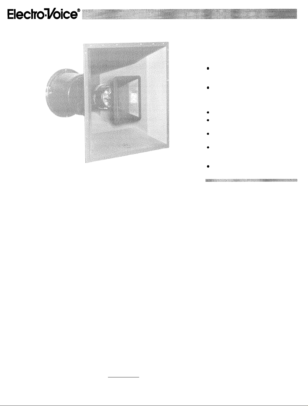
DESCRIPTION
The Electro-Voice
loaded speaker system for permanent installation. Because the mouth dimensions of both
the mid-bass and high-frequency horns were
correctly chosen and are large enough with
respect
MH660C
down to 500Hz.
increases speech intelligibility and musical clarity in difficult acoustic environments.
horn systems wlth smaller radlatlng areas
simply cannot provlde the hlgh degree of
directional control associated with the
MH660C.
cm (28.0 in.)
27.2 kg (60 lb)
33.6 kg (74 lb)
MH660C is a two-way horn-
to the wavelengths reproduced, the
provides unifon directivity control
This super directivity control
and
control to
intelligibility
under
horn
barrier strip;
with composite
Other
Page 2
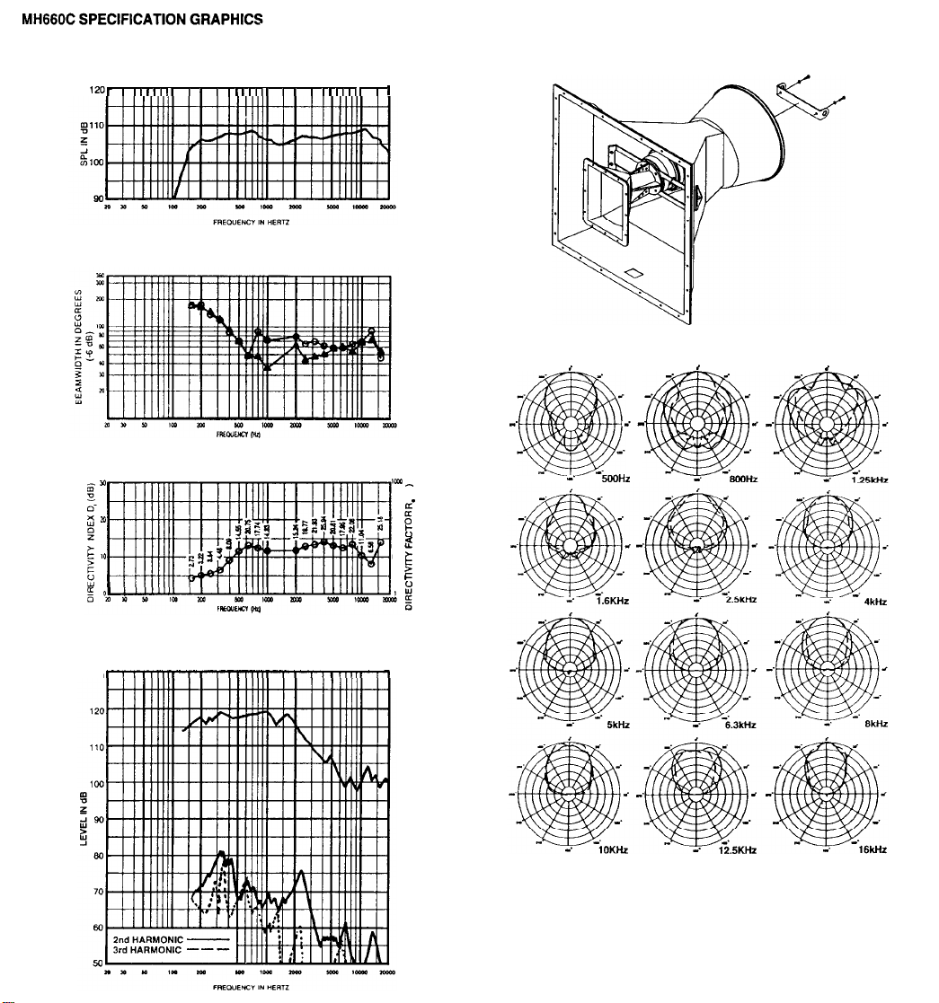
FIGURE
1
-
Typical Axial Frequency Response (anechoic
environment, 1 watt/1 meter into mid-bass section)
, , , , , , ,,,,,, , , , , ,,
FIGURE 2 - Beamwidth vs. Frequency
,,,, , , , , ,,,
FIGURE 6 -
Hanging Points
,
FIGURE 3
FIGURE 4 -
-
Directivity
*
1
Harmonic
bass horn using typical
130
Factor and Directivity Index vs. Frequency
Distortion (120 dB SPL at one meter from
music
spectrum)
‘W_
I(D g
I0 i
a
d
t,
0
mid-
FIGURE 6 - Polar Response
“.
,
_’
5OOHZ
HORIZONTAL
,
-
VERTICAL - -
,
-
Page 3

The
MH660C
is a 60 x 60 deg. two-way system
with mid-bass and high-frequency horns that
are coaxially mounted. The common acoustic
axes of these horns ensures smooth response
and coverage in the crossover region when the
appropriate signal delay is applied to the
high-
frequency driver.
Delivering smooth and extended performance,
the high-frequency section operates from 1,600
to 20,000 Hz and consists of a specially
developed, low-profile
driver coupled to an HP64 60 x 60
DH2As2
compression
constantdirectivity horn. The HP66 horn features integral fiberglass-and-zinc construction for exceptional strength and performance.
Beamwidthcontrol vanes in the horn throat correct all
coverage anomalies in the
10-
to
20-kHz
octave. This horn and driver combination is securely mounted to the mid-bass horn by a
heavy-duty steel bracket.
The mid-bass system is composed of a
DL1
0X-SH 24.5-cm (10-in.) reproducer
mounted on a MH660 60 x 60 deg. mid-bass
horn. The
Kevlar epoxy
DL10X-SH
reproducer contains a
cone, which is twice as strong as
the conventional paper cone. The mid-bass
section operates between 140 and 1,600 Hz,
and features a proprietary phase plug (U.S.
patent no.
4,718,517)
which extends the
highend output to blend seamlessly into the coaxial
high-frequency section.
If the MH660C is used in a full-range application, additional low-frequency reinforcement,
such as the PI1 15L or a TL-series enclosure
will be required.
APPLICATIONS
The
MH660C
has been designed specifically
with the permanent installation market in mind.
Sports arenas, performing arts centers, auditoriums and large gymnasiums are all candidates
for the
MH660C.
control, the
used in almost any situation. The
sound pedigree of the
With its superior directivity
MH660C
is a system that can be
MH660C
is evident by
concert-
the ease of installation and by the use of professional-grade components throughout the line.
SUSPENDING
MH660C ENCLOSURES
Suspending any object is potentially dangerous and should only be attempted by individuals who have a thorough knowledge of the
techniques and regulations of rigging objects
overhead.
that the
Electro-
Voice strongly recommends
MH66OC
be suspended taking into
account a// current national, federal, state and
local regulations. It is the responsibility of the
installer to ensure the
MH660C
is safely installed in accordance with all such regulations.
If
the
MH660C
is suspended,
Electro-Voice
strong/y recommends that the system be inspected af
least
once a year. If any sign of
weakness or damage is detected, remedial
action should be taken immediate/y.
A manual entitled installing the MH Series is
available from Electro-Voice. It is included with
every MH system and should be followed carefully. A general overview is included here to
help the system designer. This overview does
not replace
the installing the
MHSeries manual,
which includes additional information on suspending, configuring and equalizing the MH
series.
1.
Kevlar is a
registered
trademark of
Dupont.
The
MH660C
front brackets and the rear
can be suspended using the two
“U”
bracket (see
Figure 5). Therear "U” bracket must be screwed
to the rear cover with the bolts provided. Each
of the mounting brackets contains a %-in.-
diameter hole through which a shackle or chain
link could pass. The
MH660C can be oriented
in any direction. Electro-Voice strongly recommends that each
MH660C be suspended independently using at least three of the four suspension points provided.
If the
MH660C
is
suspended, it is recommended
that the unit be inspected at least once a year.
If any sign of weakness is detected, remedial
action should be taken immediately.
CAUTION: The
should be suspended overhead
cordance with the procedures and
MH660C
speaker systems
only In ac-
Iimitatfons specified in the installation manual
Included wlth the systems.
CONNECTIONS
Each frequency section can be individually
connected via #10 screw terminals. All drivers
are connected with the same polarity. A posi-
tive voltage applied to the positively marked
terminal produces a positive acoustic pressure
at the front of the system.
CROSSOVER, EQ AND SIGNAL DELAY
The
MH660C
is a two-way system which must
be biamped with a separate active crossover.
24-dB-per-octave crossover slopes are assumed for maximum performance and reliabil-
ity. For optimum performance, EQ and signal
delay are required. (Note: the delays noted
below are for fourth-order
(24-dB-per-octave)
Linkwitz-Riley crossover filter characteristics.)
The mid-bass section should be crossed over
to match the low-frequency section and at
1,600 Hz at the high end. No signal delay or
overall broadband EQ is required. The
frequency section requires a
1,600-Hz
high-
cross-
over and the typical constant-directivity-horn
high-frequency boost EQ. A
0.6-msec
signal
delay provides the smoothest response in the
crossover region. A low-frequency blocking
capacitor with a
3-dB-down
point of 800 Hz is
included.
An Electro-Voice XEQ-3 electronic crossover/
equalizer/time delay unit with EQW plug-in
module provides all of the necessary signal
processing. The
XEQ-3
is a three-way electronic crossover with adjustable crossover frequencies utilizing Linkwitz-Riley 24-dB-per-octave filters and signal delay equalization to
achieve zero lobbing error.
FREQUENCY RESPONSE
The
MH660C
measured in Electro-Voice’s large
axial frequency response was
anechoic
chamber at a distance of 3 meters (10 feet) with
a swept sine-wave input (see Figure 1). It has
been normalized for 1 watt/l meter into the
midbass section. Minimal level adjustment and
equalization have been used.
DIRECTIVITY
The directional characteristics of the MH660C
were measured in Electro-Voice’s large
anechoic
chamber, with a test signal of
onethird-octave filtered pink noise at the frequencies indicated. A full spherical measurement
system, which is fully compatible with ElectroVoice’s
AcoustaCADD
computer-aided design program, was used. All directional information was measured at 6.1 meters (20 feet).
Figure 6 illustrates the nominal horizontal and
vertical polar responses, with the long system
axis vertical. If the mid-bass/high-frequency
module is rotated, then the horizontal and vertical polars should be interchanged.
Figure 2 illustrates the horizontal and vertical
beamwidths. Beamwidth is
the
angle at which
the horizontal and vertical polar responses
have decreased in level by 6
dB
when com-
pared to the on-axis frequency response.
Figure 3 represents the total directivity of the
MH660C
The directivity factor R, (Q) is the
relative value, at a point, when compared to an
ideal spherical response. The directivity index
(D,) is calculated by D, =
10log,,,Re
SERVICE
In the unlikely event the
MH660C
requires
service, each driver can be replaced or repaired. A service data sheet is available from
Electro-Voice.
POWER-HANDLING TEST
Electro-Voice components and systems are
manufactured to exacting standards, ensuring
they will hold up, not only through the most
rigorous of powertests, but also through continued use in arduous, real-life conditions. Two
main test specifications are used: the AES
Recommended Practice for Specification of
Loudspeaker Components Used in Professional
Audio and Sound Reinforcement (AES2-1984/
ANSI
S4.26-1984)
Power Rating Full Range
and the EIA Loudspeaker
(ANSI/EIA
RS-426-A
1980). Both of these specifications use random-noise spectrums which mimic typical music and test the thermal and mechanical capabilities of the components. Electro-Voice will
support relevant additional standards as and
when they become available. Extreme, in-house
power tests,
which push
the performance boundaries of the components, are also performed
and passed to ensure years of trouble-free
service.
Specifically, the MH660C high-frequency section passes AES2-1984/ANSI S4.26-1984 with
the following values:
Z,,,
= 6.0 ohms at 7,000 Hz
P
= 60 watts
Test Voltage
Selected decade =
The
MH660C
= 19.0 volts rms,
38.0 volts peak
1,500-15,000
(+6 dB)
Hz
mid-bass section passes ANSI/
EIA RS-426-A 1980 with the following values:
R,, =
6.9 ohms (1.15 x RJ
P
= 300 watts
Test Voltage =
45.5 volts rms.
91 .0 volts peak
(+6 dB)
ARCHITECTS’ AND ENGINEERS’
SPECIFICATIONS
The loudspeaker system shall be a two-way,
active, horn-loaded type. The mid-bass
frequencies shall be reproduced by a single DL10X-
SH
25.4-cm
(10-in.) driver coupled to a
MH660
60 x 60 deg. constant-directivity horn. High
frequencies shall be reproduced by a
DH2As2 2-inch
compression driver coupled to
60-watt
an HP66 60x60 deg. constant-directivity horn.
The mid-bass and high-frequency devices shall
be coaxially mounted. The system will reproduce frequencies from 140 to 20,000 Hz and
have a nominal coverage pattern of
60 x 60 deg.
The directivity control shall be maintained down
to 500 Hz. The crossover frequency shall be
1,600 Hz. The module shall be capable of
producing average sound levels in excess of
Page 4

128 dB (1 watt/l meter) in the long term, with
short-term peaks of 134
made to provide four safe suspension points,
made from 10-gauge steel.
The dimensions shall be 68.6 cm (27.0 in.) tall,
68.6 cm (27.0 in.) wide, and 71.1 cm (28.0 in.)
deep. Weight shall be 33.6 kg (74 lb).
The loudspeaker system shall be the
Electro-Voice MH660C.
UNIFORM LIMITED WARRANTY
Electro-Voice products are guaranteed against
malfunction due to defects in materials or workmanship for a specified period, as noted in the
individual product-line statement(s) below, or in
the individual product data sheet or owner’s
manual, beginning with the date of original
purchase. If such malfunction occurs during the
specified period, the product will be repaired or
replaced (at our option) without charge. The
product will be returned to the customer prepaid. Exclusions and Llmltations: The Limited Warranty does not apply to: (a) exterior
finish or appearance; (b) certain specific items
described in the individual product-line
statement(s) below, or in the individual product
data sheet or owner’s manual; (c) malfunction
resulting from use or operation of the product
other than as specified in the product data
sheet or owners manual; (d) malfunction re-
dB.
Provision shall be
sulting from misuse or abuse of the product; or
(e) malfunction occurring at any time after repairs have been made to the product by anyone
other than Electro-Voice or any of its authorized
service representatives. Obtaining
Service:
tomer must deliver the product, prepaid, to
Electro-Voice or any of its authorized service
representatives togetherwith proof of purchase
of the product in the form of a bill of sale or
receipted invoice. A list of authorized service
representatives is available from Electro-Voice
at 600 Cecil Street, Buchanan, MI 49107 (616/
6956831 or
Consequential Damages Excluded:
repair or replacement and return to the customer are the only remedies provided to the
customer. Electro-Voice shall not be liable for
any incidental or consequential damages including, without limitation, injury to persons or
property or loss of use. Some states do not
allow the exclusion or limitation of incidental or
consequential damages so the above limitation
orexclusion may not apply to you. Other Rights:
This warranty gives you specific legal rights,
and you may also have other rights which vary
from state to state.
Electro-Voice Speakers and Speaker Systems are guaranteed against malfunction due
to defects in materials or workmanship for a
period of five (5) years from the date of original
To obtain warranty service, a cus-
800/234-6831). lncidental
Warranty
and
Product
purchase. The Limited
to burned voice coils or malfunctions such as
cone and/or coil damage resulting from improperly designed enclosures. Electro-Voice active
electronics associated with the speaker systems are guaranteed for three (3) years from
the date of original purchase. Additional details
are included in the Uniform Limited Warranty
statement.
Electro-Voice
closure-mounted hardware and
sories) is guaranteed against malfunction due
to defects in materials or workmanship for a
period of one (1) year from the date of original
purchase. Additional details are included in the
Uniform Limited Warranty statement.
Electro-Voice Accessories are guaranteed
against malfunction due to defects in materials
or workmanship for a period of one (1) year from
the date of original purchase. Additional details
are included in the Uniform Limited Warranty
statement.
Service and repair address for this product:
Electro-Voice, Inc.,
Michigan 49107
6831).
Specifications subject to change without no-
tice.
Warranty
Flying Hardware(including en-
600 Cecil
(616/695-6831
does not apply
rigging acces-
Street, Buchanan,
or
800/234-
 Loading...