

Page 1
R
R
LPA500 UHF Log Periodic Antenna
Owner’s Manual
Description
The Electro-Voice LPA500 is a broadband di
rectional log periodic antenna. It is optimized for
reception of frequencies from 450 to 900 MHz.
The gain of this antenna enables it to receive
signals from a greater distance than a typical
“whip” type antenna.
SPECIFICATIONS
(Typical)
Gain..................................................................................................................................4.6 dBd
1/2 Power Beam Width ........................................................................................................120°
Front-to-Back Ratio ..........................................................................................................19.4dB
SWR.......................................................................................................................................1.5:1
Input Impedance ................................................................................................................50 ohm
Input Connector ....................................................................................................................TNC
Log periodic antennas are very directional and
will have the best reception when pointed at the
transmitter. This design also means less interfer
ence from unwanted signals coming from the
back or side of the antenna.
-
Placement
The LPA500 should be placed in a position that
has a clear, unobstructed path to the transmitter.
Obstructions to the signal such as walls, ceilings
and metal objects will reduce range and perfor
mance.
Generally speaking, placing the LPA500 at an
elevated location will yield the best performance
over the largest area.
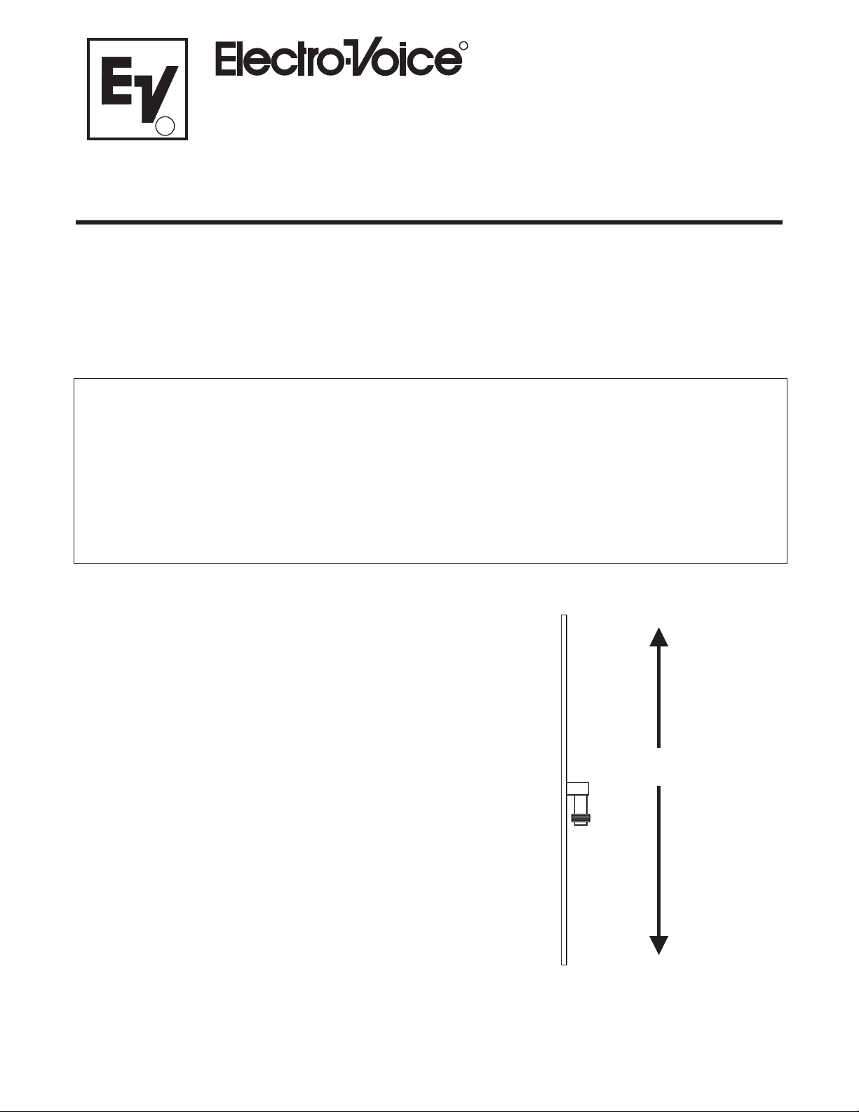
Antenna Mounting
The LPA500 is supplied with a variety of
mounting hardware to make installation easy. It
should always be mounted vertically with the
arrow pointing towards the transmitters(s). See
Figure 1. when oriented correctly, the LPA500
will appear as a thin piece of metal when
viewed from the transmitter’s position.
For best results, do not clamp the LPA500 to
horizontal metal objects that extend past the
clamp (see Figure 5). Metal rods or other objects
that block part of the large face of the antenna
will detune it and cause loss of performance.
-
MOUNT
VERTICALLY
END VIEW
Figure 1
Antenna Mounting
-1-
Page 2
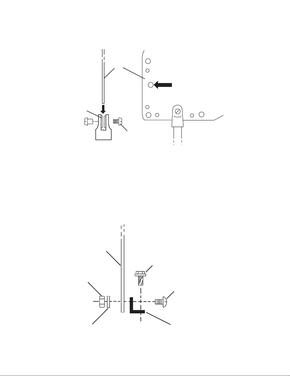
Microphone Stand Adapter
Attach the microphone stand adapter using the
screws and spacers supplied with it. See Figure 2.
LPA500
SPACERS
SCREW
ALTERNATE
LOCATION FOR
MIC BOOM
FRONT VIEW
Figure 2
Microphone Stand Adapter
Angle Bracket
Attach the angle bracket using the nuts,
lockwashers, and screws supplied with it. Self
tapping screws are supplied for securing the
bracket to wood, metal, or other surfaces. See
Figure 3.
LPA500
NUT
SIDE VIEW
TAPPING SCREW
LOCKWASHER
SLOTTED SCREW
ANGLE BRACKET
Figure 3
Angle Bracket
-2-
Page 3

Clamps
Clamps are provided for mounting the LPA500 on
pipes, scaffolds, tree limbs, etc.. Attach the
clamps with the hardware supplied. See Figure 4.
LPA500
BOLT
LOCKWASHER
NOTE OFFSET
IN CLAMPS
WING NUT
Figure 4
Clamps
Do not clamp the antenna to horizontal metal
objects that extend past the clamp. See Figure
5. This will detune the antenna and cause loss
of range and performance.
LPA500
R
THIS END TOWARD TRANSMITTER
UHF
LOG PERIODIC ANTENNA
GOOD
BAD
Figure 5
Clamp Mounting
-3-
Page 4

Connectors and Cable
The LPA500 is equipped with a TNC connector
to provide reliable signal connection. To avoid
signal strength reduction, special low-loss cables
should be used. These are avai lable fr om
Electro-Voice in the following lengths:
MOUNTING SUGGESTIONS
Model Part Number Length
CXU-10 690419 10 ft (3 M)
CXU-25 71151-025 25 ft (7.6 M)
CXU-50 71151-050 50 ft (15 M)
CXU-75 71151-075 75 ft (23 M)
CXU-100 71151-100 100 ft (30 M)
LPA500
R
UHF
THIS END TOWARD TRANSMITTER
Mic Boom
LPA500
R
THIS END TOWARD TRANSMITTER
UHF
LOG PERIODIC ANTENNA
LOG PERIODIC ANTENNA
LPA500
R
THIS END TOWARD TRANSMITTER
Mic Stand
UHF
LOG PERIODIC ANTENNA
LPA500
R
THIS END TOWARD TRANSMITTER
UHF
LOG PERIODIC ANTENNA
Wall
Top Surface
-4-
Page 5

LPA500
R
THIS END TOWARD TRANSMITTER
UHF
LOG PERIODIC ANTENNA
LPA500
R
THIS END TOWARD TRANSMITTER
CUT OFF IF POSSIBLE
UHF
LOG PERIODIC ANTENNA
Pipe or Scaffold
LPA500
R
THIS END TOWARD TRANSMITTER
UHF
LOG PERIODIC ANTENNA
Tree Limb
Combination:
Bracket with Clamps
-5-
Page 6

Uniform Limited Warranty
Electro-Voice products are guaranteed against malfunction due to defects in materials or
workmanship for a specified period, as noted in the individual product-line statement(s) be
low, or in the individual product data sheet or owner’s manual, beginning with the date of
original purchase. If such malfunction occurs during the specified period, the product will be
repaired or replaced (at our option) without charge. The product will be returned to the cus
tomer prepaid.
Exclusions and Limitations: The Limited Warranty does not apply to: (a) exterior finish or
appearance; (b) certain specific items described in the individual product-line statement(s)
below, or in the individual product data sheet or owner’s manual; (c) malfunction resulting
from use or operation of the product other than as specified in the product data sheet or
owner’s manual; (d) malfunction resulting from misuse or abuse of the product; or (e) mal
function occurring at any time after repairs have been made to the product by anyone other
than Electro-Voice or any of its authorized service representatives.
Obtaining Warranty Service: To obtain warranty service, the customer must deliver the
product, prepaid, to Electro-Voice or any of its authorized service representatives together
with proof of purchase of the product in the form of a bill of sale or receipted invoice. A list
of authorized service representatives is available from Electro-Voice at 600 Cecil Street, Buchanan, MI 49107 (616/695-6831 or 800/234-6831).
-
-
-
Incidental and Consequential Damages Excluded: Product repair or replacement and return to the customer are the only remedies provided to the customer. Electro-Voice shall not
be liable for any incidental or consequential damages including, without limitation, injury to
persons or property or loss of use. Some states do not allow the exclusion or limitation of incidental or consequential damages so the above limitation or exclusion may not apply to you.
Other Rights: This warranty gives you specific legal rights and you may also have other
rights which vary from state to state.
Electro-Voice Wireless Systems are guaranteed against malfunction due to defects in mate
rials or workmanship for a period of one (1) year from the date of original purchase. The
Limited Warranty does not extend to cables or cable connectors. Additional details are in
cluded in the Uniform Limited Warranty Statement.
Service and repair addresses for this product:
Electro-Voice, 12000 Portland Ave. South, Burnsville, MN 55337
(952) 884-4051, (800) 828-6107 FAX (952) 887-9212
and
Telex Communications, Inc.
8601 East Cornhusker Highway,
Lincoln, Nebraska 68507 (402/467-5321).
-
-
-6-
Page 7

R
12000 Portland Ave. South, Burnsville, MN 55337
(952) 884-4051, (800) 828-6107 FAX (952) 887-9212
MANUAL - LPA500 ©Telex Communications, Inc. • July 2002 • Litho in U.S.A. Part Number 801752
 Loading...