

Page 1
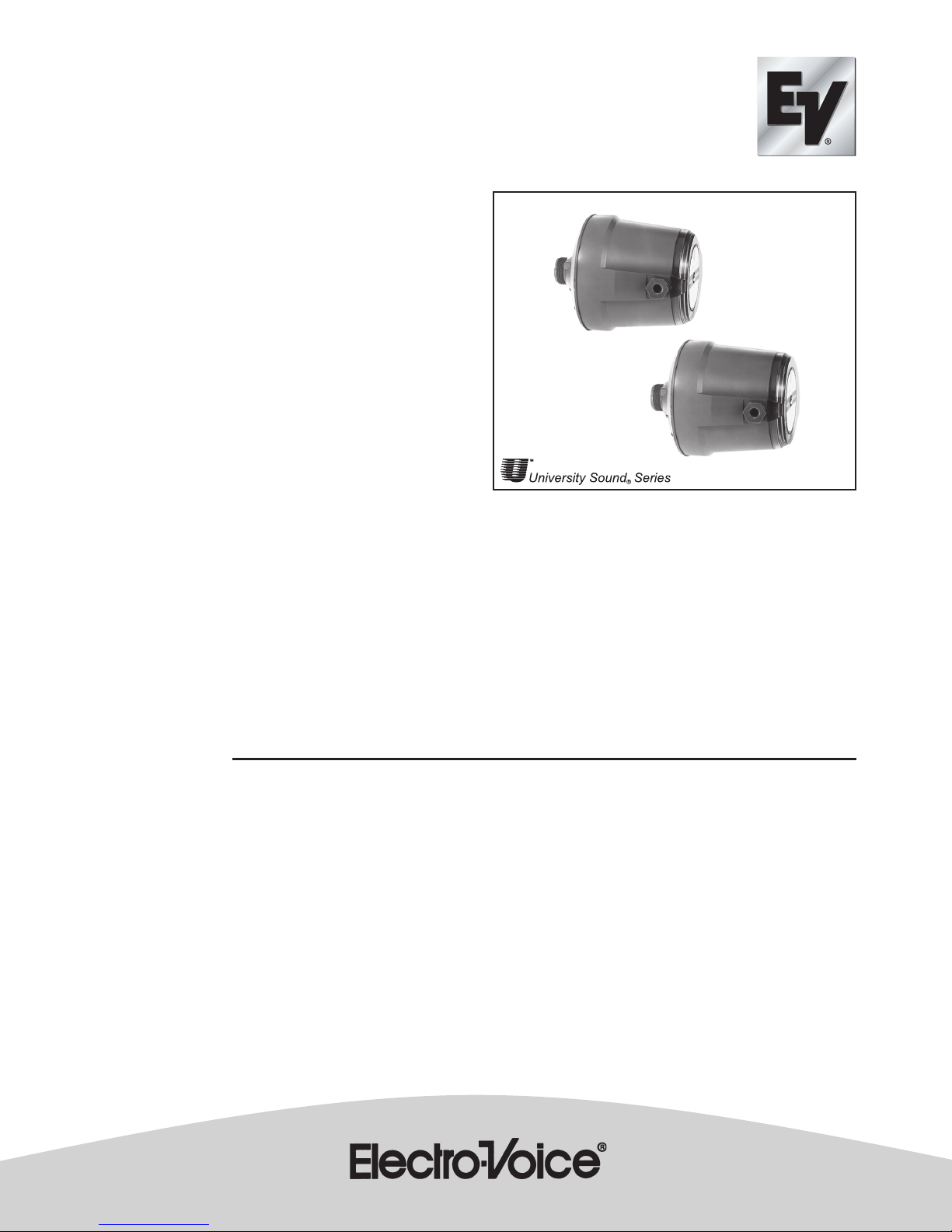
ID60D-8
ID60DT
General Product Description
The ID60D-8 and ID60DT are heavy-duty compression
drivers for use in high-power public address installations.
The drivers employ rugged phenolic diaphragms, 2-inch
diameter voice coils and “rim centered” ferrite magnet
structures for long life and reliability under extreme operating
conditions.
A hinged cycolac rear housing for easy access and
connection to a sound system, via a BX conduit connector,
is provided together with a plug-in, field replaceable
diaphragm assembly.
The transformer model (ID60DT) includes connections for
25-V and 70-V distributed systems and a screwdriver
operated power-tap select switch.
The exterior is finished in durable, weatherproof paint, and
all metal parts have been tropicalized for resistance to high
humidity and fungus.
Ideal for both indoor and outdoor applications, these drivers
are well suited for any installation requiring rugged,
high-power performance.
Architects’ and Engineers’ Specifications
The loudspeaker(s) shall be of the compression-driver type
utilizing a rugged phenolic diaphragm and a
high-temperature rated, 2-in. diameter voice coil.
The loudspeaker(s) shall exhibit essentially flat power
response from 300 to 4,000 Hz with a smoothly rolled-off
response beyond. Their sensitivity, when mounted on a PH
horn, will be 108 dB (1 W/1 m) with a 500- to 5,000-Hz
pink-noise signal applied.
Heavy-Duty
Compression Drivers
The loudspeaker(s) shall be capable of handling a 60-watt,
500- to 5,000-Hz pink-noise signal with a 6-dB crest factor
for a period of 8 hours.
The loudspeaker(s) shall have a diameter of 14.3 cm (5.6
in.) and a depth of 16.2 cm (6.4 in.) They shall have a 2.41
cm (0.95 in.) throat opening with a 1 3/8-18 thread for
mounting.
The loudspeaker shall be the ID60DT, which includes a 70-V/
25-V line-matching transformer and weighs no more than 3
4 kg (7.4 lb), and the ID60D-8, which has a nominal
impedance of 8 ohms and weighs no more than 2.7 kg (5.9
lb).
COMMERCIAL
Specifications:
Frequency Response:
............................................. 300 - 4,000 Hz ±5 dB (see Figure 2)
Power Handling, 8 Hours, 6-dB Crest Factor:
............................................... 60 watts (500-5,000 Hz pink noise)
Impedance, Nominal: ...................................................... 8 ohms
Minimum:7.5 ohms (Cobraflex Horns above 500 Hz)
Sound Pressure Level at 1 Meter, 1 Watt Input Averaged, Pink
Noise Band-Limited from 300-3,000 Hz:
..................................................................................... See Table I
Voice Coil Diameter: .......................................... 5.08 cm (2.0 in.)
Magnet Weight: ................................................... 0.48 kg (1.06 lb)
Magnet Material: ................................................ Strontium ferrite
Flux Density: ............................................................... 1.17 Tesla
Construction:
Rugged diecast housing with weatherproof finish for outdoor
use
Mechanical Construction of Driver:
1 3/8"-18 thread, 1/2 long allows the ID60 to be mounted on
any University Sound horn.
Dimensions:
Diameter: ..................................................... 14.3 cm (5.6 in.)
Height: .......................................................... 16.2 cm (6.4 in.)
Net Weight:
ID60D-8: .................................................. 2.7 kg (5.9 lb)
ID60DT: .................................................. 3.4 kg (7.4 lb)
Shipping Weight:
D60D-8:: .................................................. 2.9 kg (6.3 lb)
ID60DT: .................................................. 3.6 kg (7.9 lb)
Recommended Horns:
Cobreflex IIB, Cobreflex III, PH, 2WP, SMH, SH
Page 2
Installation
Remove the plastic cap from the threaded throat of the driver and screw
the driver into the horn until firmly seated.
Install the horn/driver assembly in intended location, referring to the
instructions provided with the horn.
Loosen the captive screw in the center of the plastic cover at the rear of the
driver, and open the hinged cover to expose wiring. Note the O-ring in the
annular housing groove.
Loosen the gland nut in the side of the driver housing enough to admit the
loudspeaker wire/cable. Alternately, a 1/2-inch conduit fitting can be
substituted for the gland nut. However, the sealing washer must be retained.
For the ID60DT, connect the loudspeaker wires to the “com” terminal and
the appropriate line terminal (25 V or 70 V). For the ID60D-8, connect to the
“com” and “8-ohm” terminals.
Tighten the gland nut securely and check that the O-ring is positioned
correctly before closing the clear plastic cover.
Low-Frequency Driver Protection
When frequencies below the low-frequency cutoff for the horn assembly
are fed to the driver, excessive current may be drawn by the driver. For
protection of driver, amplifier, and transformer (if driver with built-in
transformer is used), capacitor(s) in series with driver, or transformer primary
are recommended. Table I indicates recommended values. The values
shown are for 200 Hz. Values for other frequencies can be determined by
using the formula:
Values shown in the following table
C =
C
x 200
200
[
C
200
]
f f = New Frequency
For drivers without transformers: 8-ohm driver, 25 V - 100 mf 150 Vdc or
150 V non-polarized electrolytic, or two 150 Vdc electrolytics of two times
required value in series, back to back, for 70 volt lines.
nroHM1@W1rofLPS
BIIxelferboCBd701
IIIxelferboCBd701
Table I. Sound Pressure Level for ID60 with Various Horns
seniLtloV-07seniLtloV-52
rewoPecnadepmIecnaticapaCecnadepmIecnaticapaC
W06smho3801
fm
W03smho6615fmsmho1204
W51smho3332fmsmho2402
W5.7smho7661fmsmho3801
W57.3smho003,15.0
W88.1smho007,22.0
fm
fm
smho0108
fm
fm
fm
fm
smho6615
smho3332
fm
fm
Table II. Series Protection Capacitors for 200 Hz and Below
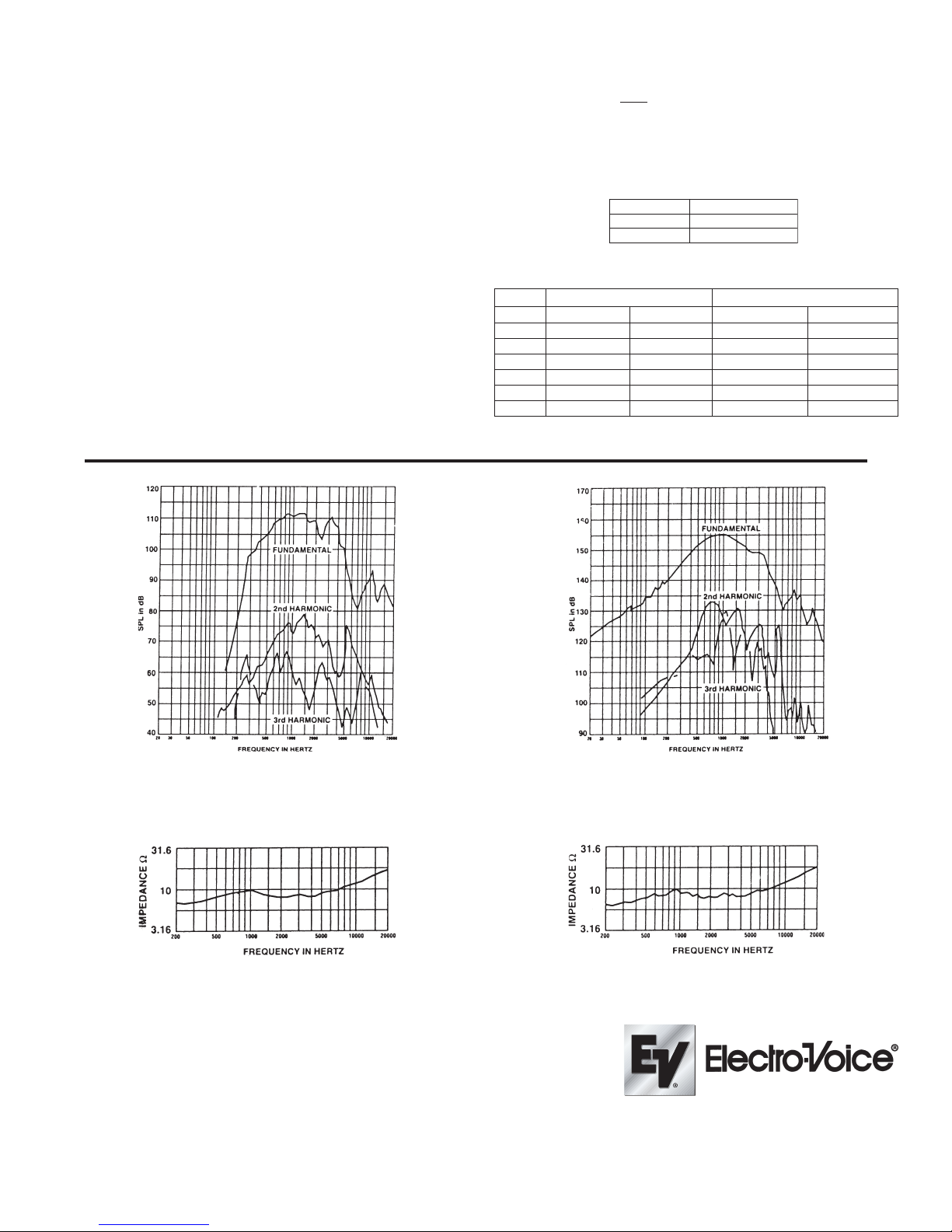
Disortion Response - Plane Wave Tube (1 inch)
Figure 1.
(6 watt input)
Figure 3.
Impedance Response - Plane Wave Tube (1 inch)
USA 12000 Portland Ave South, Burnsville, MN 55337, Phone: 952-884-4051, FAX: 952-884-0043
Canada 705 Progress Avenue, Unit 46,Scarborough, Ontario, Canada, M1H2X1,Phone: 416-431-4975, 800-881-1685, FAX: 416-431-4588
Switzerland Keltenstrasse 11, CH-2563 IPSACH, Switzerland, Phone: 41/32-331-6833. FAX: 41/32-331-1221
Germany Hirschberger Ring 45, D94315, Straubing, Germany, Phone: 49 9421-706 392, FAX: 49 9421-706 287
France Parc de Courcerin, Alle Lech Walesa, Lognes, 77185 Marne La Vallee, France, Phone: 33/1-6480-0090, FAX: 33/1-6480-4538
Australia Unit 23, Block C, Slough Business Park, Slough Avenue, Silverwater, N.S.W. 2128, Australia, Phone: 61/2-9648-3455, FAX: 61/2-96 48-5585
Hong Kong Unit E & F, 21/F, Luk Hop Industrial Bldg., 8 Luk Hop St., San PO Kong, Kowloon, Hong Kong, Phone: 852-2351-3628, FAX: 852-2351-3329
Japan 2-5-60 Izumi, Suginami-ku,Tokyo, Japan 168, Phone: 81-3-3325-7900, FAX:81-3-3325-7789
Singapore 3015A Ubi Rd 1, 05-10, Kampong Ubi Industrial Estate, Singapore 408705, Phone: 65-746-8760, FAX: 65-746-1206
Mexico Av. Parque Chapultepec #66-201, Col. EI. Parque Edo. Mex. 53390, Phone: (52) 5358-5434, FAX: (52) 5358-5588
UK 4, The Willows Centre, Willow Lane, Mitcham, Surrey CR4 4NX, UK, Phone: 44 181 640 9600, FAX: 44 181 646 7084
Africa, Mid-East 12000 Portland Ave South, Burnsville, MN 55337, Phone: 952-887-7424, FAX: 952-887-9212
Latin America 12000 Portland Ave South, Burnsville, MN 55337, Phone: 952-887-7491, FAX: 952-887-9212
www.electrovoice.com • Telex Communications, Inc. • www.telex.com
© Telex Communications, Inc. 02/2001
Part Number 38109-855 Rev A
Disortion Response - FC100 Horn
Figure 2.
Figure 4.
Impedance Response - FC100 Horn
For customer orders, contact the Customer Service department at
For warranty repair or service information, contact the Service
For technical assistance, contact Technical Support at 866/78 AUDIO
Please refer to the Engineering Data Sheet for warranty information.
800/392-3497 Fax: 800/955-6831
Repair department at 800/685-2606
Specifications subject to change without notice.
U.S.A. and Canada only.
 Loading...