

Page 1
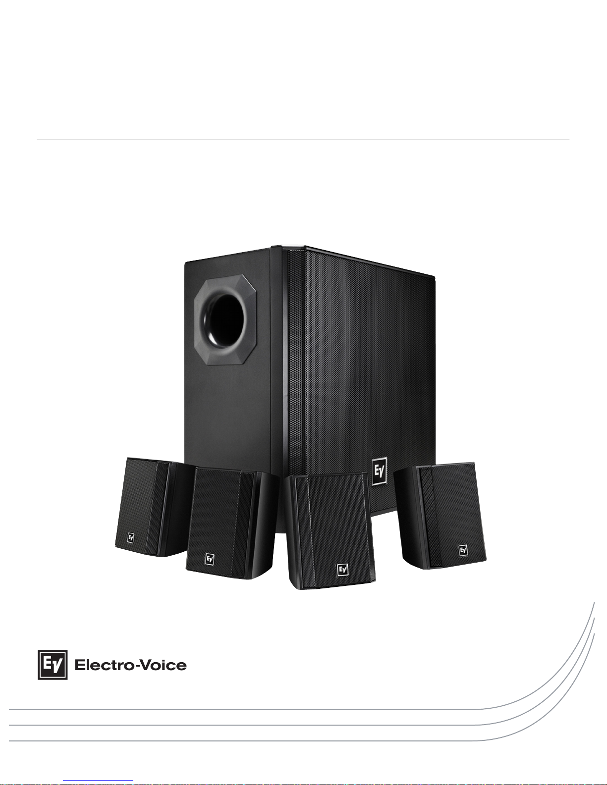
EVID Compact Sound Speaker System
EVID-S44, EVID-S44W, EVID-2.1, EVID-2.1W, EVID-40S, and EVID-40SW
en | Installation Manual
Page 2

Page 3

Table of contents
1
Safety 4
2
Welcome 5
2.1 System features 5
3
System overview 6
3.1 Packing lists 6
3.2 Product information 8
3.3 Dimensions 9
4
Installation 10
4.1 Surface mount satellite speaker installation 10
4.2 Wall bracket range of motion 11
4.3 Surface mount subwoofer installation 11
4.4 Removing subwoofer from the wall 13
5
Wiring 14
5.1 Wattage tap 14
5.2 70v/100v/4 ohm Mono 15
5.3 8 ohm Stereo 16
6
Troubleshooting 17
7
Technical data 18
7.1 Frequency response 18
en 3
Electro-Voice Installation Manual 2015.02 | 03 | F.01U.310.295
Page 4
Safety
!
Warning!
Suspending any object is potentially dangerous and should only be attempted by individuals
who have a thorough knowledge of the techniques and regulations of suspending objects
overhead.
Electro-Voice strongly recommends all loudspeakers be suspended taking into
account all current national, federal, state, and local laws and regulations. It is the
responsibility of the installer to ensure all loudspeakers are safely installed in accordance
with all such requirements. When loudspeakers are suspended, Electro-Voice strongly
recommends the system be inspected at least once per year or as laws and regulations
require. If any sign of weakness or damage is detected, remedial action should be taken
immediately. The user is responsible for making sure the wall, ceiling, or structure is capable
of supporting all objects suspended overhead. Any hardware used to suspend a loudspeaker
not associated with Electro-Voice is the responsibility of others.
Safety Agency Compliance
The EVID 2.1 and EVID 40S bracket systems have successfully passed EIA-636 at a safety
factor of 8:1. The bracket systems are intended to support only the
EVID 2.1 and EVID 40S
respectively. Do not use either bracket system for any other purpose. Never set anything on or
hang anything from the EVID 2.1 or EVID 40S enclosures when using the brackets.
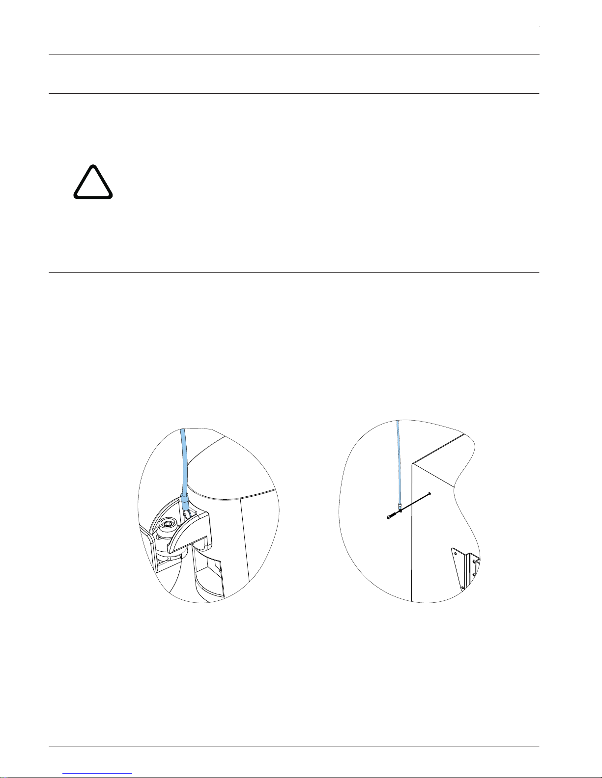
As an added safety measure, it is suggested the user install an extra suspension point back to
the building structural supports. This redundant safety point should have as little slack as
possible (less than one (1) inch is preferable).
Figure 1.1: Surface mount satellite speaker (left) and surface mount subwoofer (right) with safety cable
1
EVID Compact Sound Speaker System
2015.02 | 03 | F.01U.310.295 Installation Manual Electro-Voice
Page 5

Welcome
Thank you for purchasing the EVID Compact Sound Speaker System
. Read through this manual
to familiarize yourself with the features, applications, and precautions before you use these
products.
The EVID Compact Sound Speaker System is a very compact full-range loudspeaker ideal for
applications requiring high-quality sound. Its shape flexibility and size make it nearly invisible
for use in background/foreground music systems for restaurants, bars, patios, retail, and other
applications. The system consists of a high performance surface mount 8-inch subwoofer
module with a crossover network to support the included four (4) surface mount 2-inch
satellite speakers. The system provides for easy signal connections at the subwoofer and can
support either 4/8 ohm or 70/100v signal connections. Its high power handling allows the
system to be used in a wide variety of environments and spaces to provide high quality
background or foreground music.
System features
▪ A complete matched background/foreground music speaker solution.
▪ High power handling – system supports up to 200 watts with 8 ohm and 100 watts with
70v/100v input connections.
▪ Large 8-inch woofer for increased low frequency output.
▪ Direct connection of satellites to subwoofer — simplifies installation wiring.
▪ Convenient detachable phoenix style signal connections speed up installation time.
▪ Large high quality rigid wood subwoofer cabinet supports extended bass response.
▪ Mounting system for surface mount satellites provides secure mounting but allows for
wide-range of motion to adapt to any placement.
▪ Easily detachable wall bracket for wall mounting of subwoofer is included.
▪ Attractive subwoofer design with full face grille.
2
2.1
en 5
Electro-Voice Installation Manual 2015.02 | 03 | F.01U.310.295
Page 6
System overview
Packing lists
The EVID Compact Sound Speaker System
contains four (4) satellite speakers and one (1)
subwoofer. When you open the box for the full system you will find three (3) main boxes
inside; two (2) boxes for the satellite speakers and one (1) box for the subwoofer.
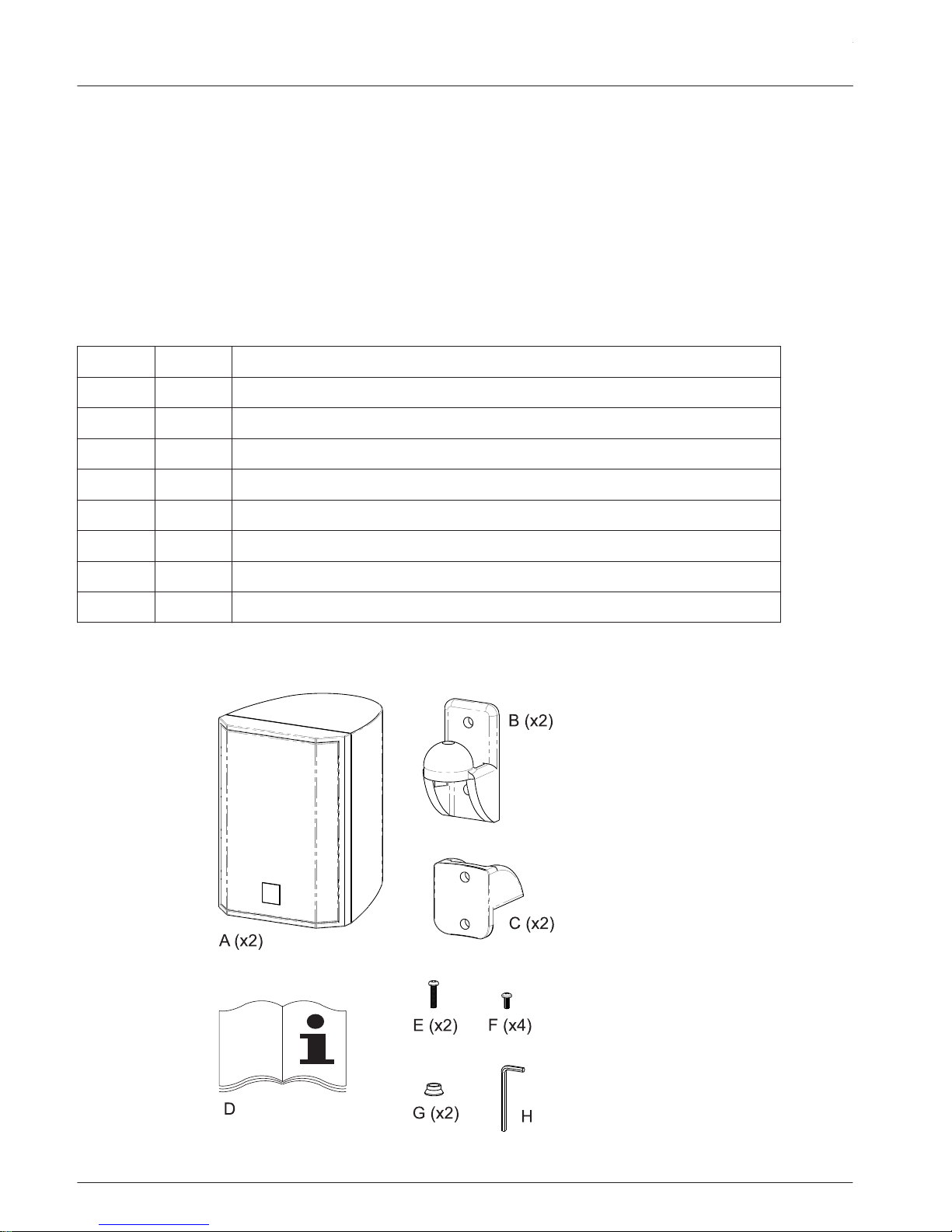
The major components included in one (1) box for the EVID 2.1 surface mount satellite
speaker.
Item Qty Description
A 2 EVID 2.1 surface mount satellite speakers
B 2 Wall brackets
C 2 Speaker brackets
D 1 EVID S44 Engineering Data Sheet
E 2 M6 hex drive pan-head screws
F 4 M5 pan-head screws
G 2 Screw sockets
H 1 Hex wrench
Table 3.1: Surface Mount Satellite Speaker (1 box)
3
3.1
EVID Compact Sound Speaker System
2015.02 | 03 | F.01U.310.295 Installation Manual Electro-Voice
Page 7
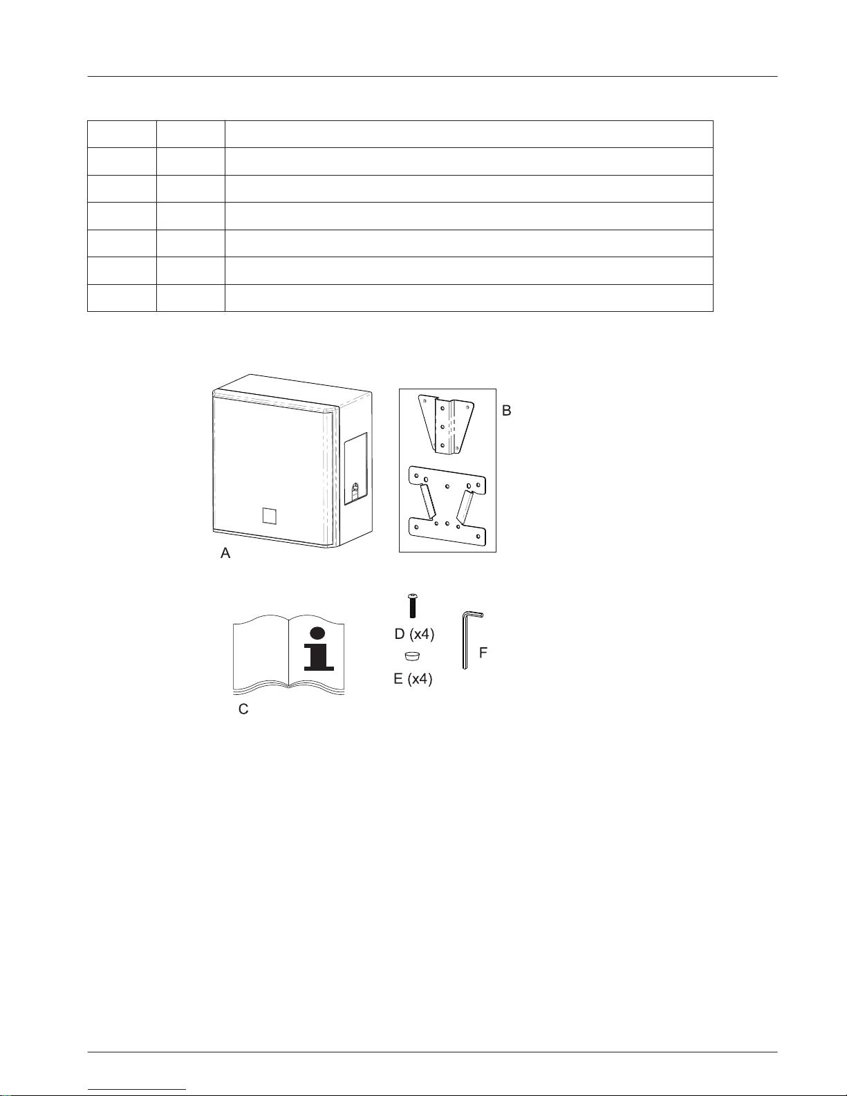
The major components included in the box for the EVID 40S surface mount subwoofer:
Item Qty Description
A 1 Surface Mount Subwoofer
B 1 Wall bracket, assembled in box
C 1 EVID Compact Sound Speaker System manual
D 4 M6 hex drive pan-head screw
E 4 Rubber feet
F 1 Hex wrench
Table 3.2: Surface Mount Subwoofer
en 7
Electro-Voice Installation Manual 2015.02 | 03 | F.01U.310.295
Page 8
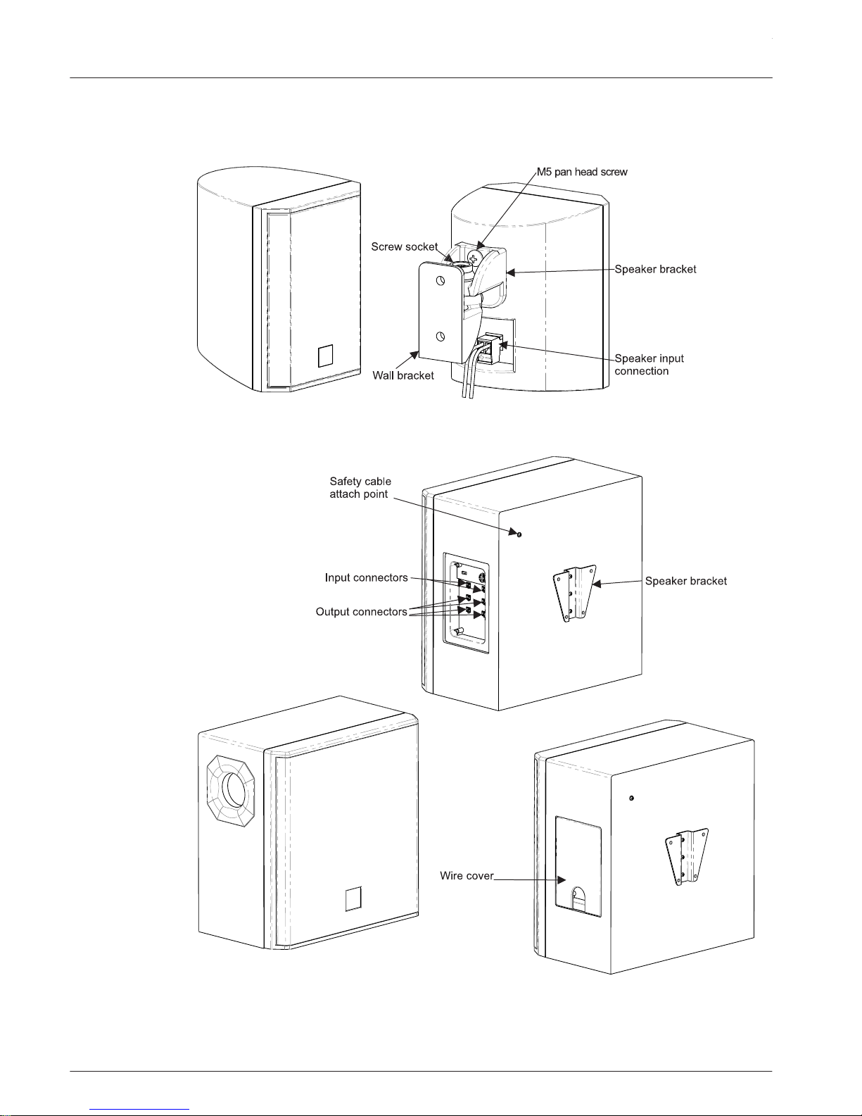
Product information
Figure 3.1: EVID 2.1 Product Information
Figure 3.2: EVID 40C Product Information
3.2
EVID Compact Sound Speaker System
2015.02 | 03 | F.01U.310.295 Installation Manual Electro-Voice
Page 9
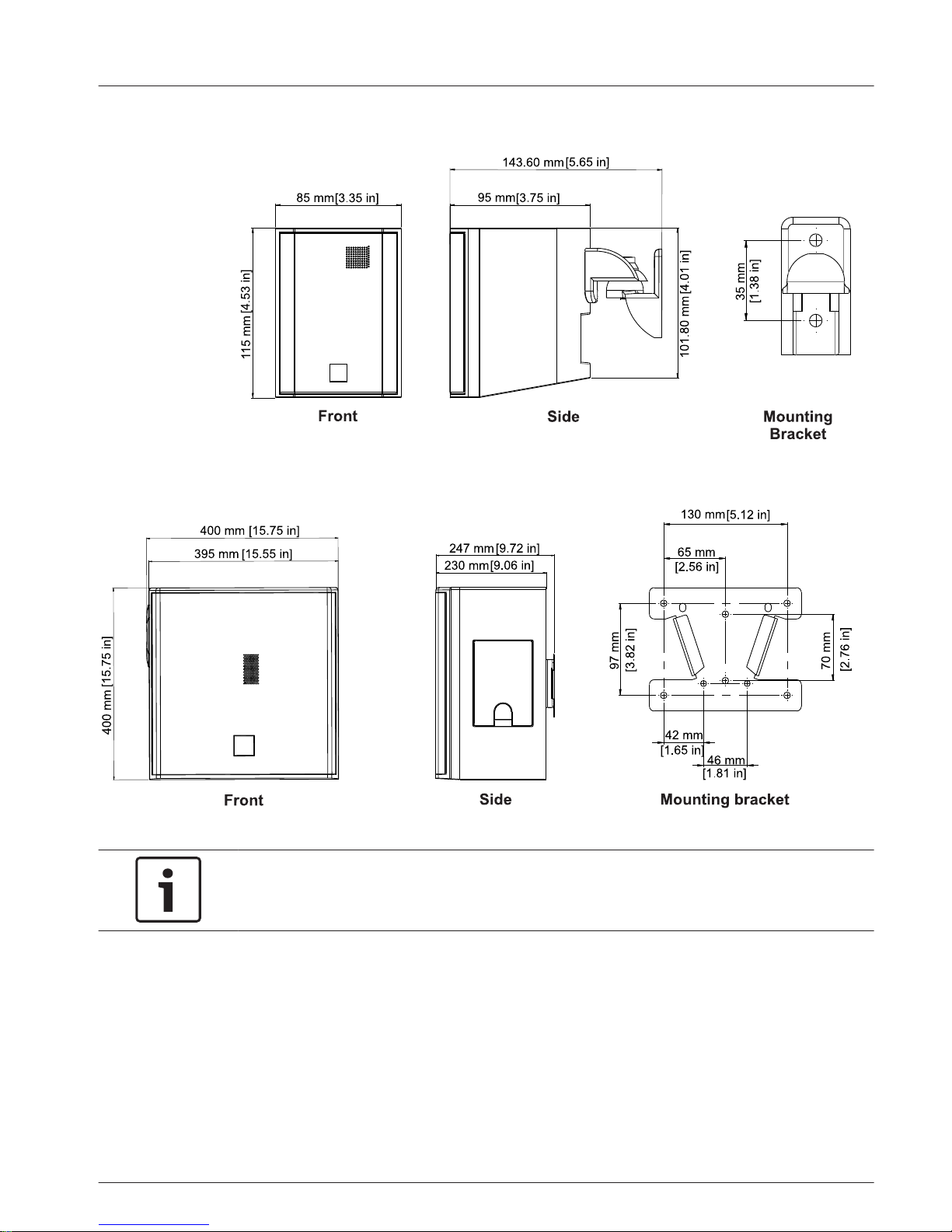
Dimensions
Figure 3.3: Dimensions EVID 2.1 and mounting bracket
Figure 3.4: Dimensions EVID 40S and mounting bracket
Notice!
The mounting bracket dimension drawings are not to scale. Drawing sizes increased for
readability.
3.3
en 9
Electro-Voice Installation Manual 2015.02 | 03 | F.01U.310.295
Page 10
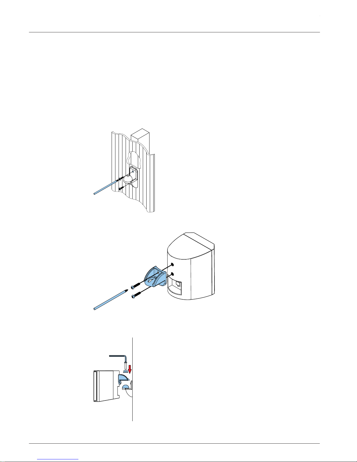
Installation
Surface mount satellite speaker installation
For safety, ensure the mounting surface supports more than the weight of the speaker. Use
only industry-accepted fasteners and mounting methods when mounting the wall bracket.
Consult an expert if you are unsure.
To install the surface mount satellite speaker, do the following:
1. Using a Phillips head screwdriver (not supplied), tighten two (2) M5 pan-head screws
(not supplied)
to attach the wall bracket to a secure mounting surface.
2. Using a Philips screwdriver, tighten two (2) M5 pan-head screws (supplied) to attach the
speaker bracket to the rear of the cabinet.
3. Place the speaker bracket onto the wall bracket.
4.
Using the hex wrench (supplied), tighten the M6 hex drive pan-head screw to secure the
speaker bracket to the wall bracket.
For more information, see Safety, page 4.
4
4.1
EVID Compact Sound Speaker System
2015.02 | 03 | F.01U.310.295 Installation Manual Electro-Voice
Page 11
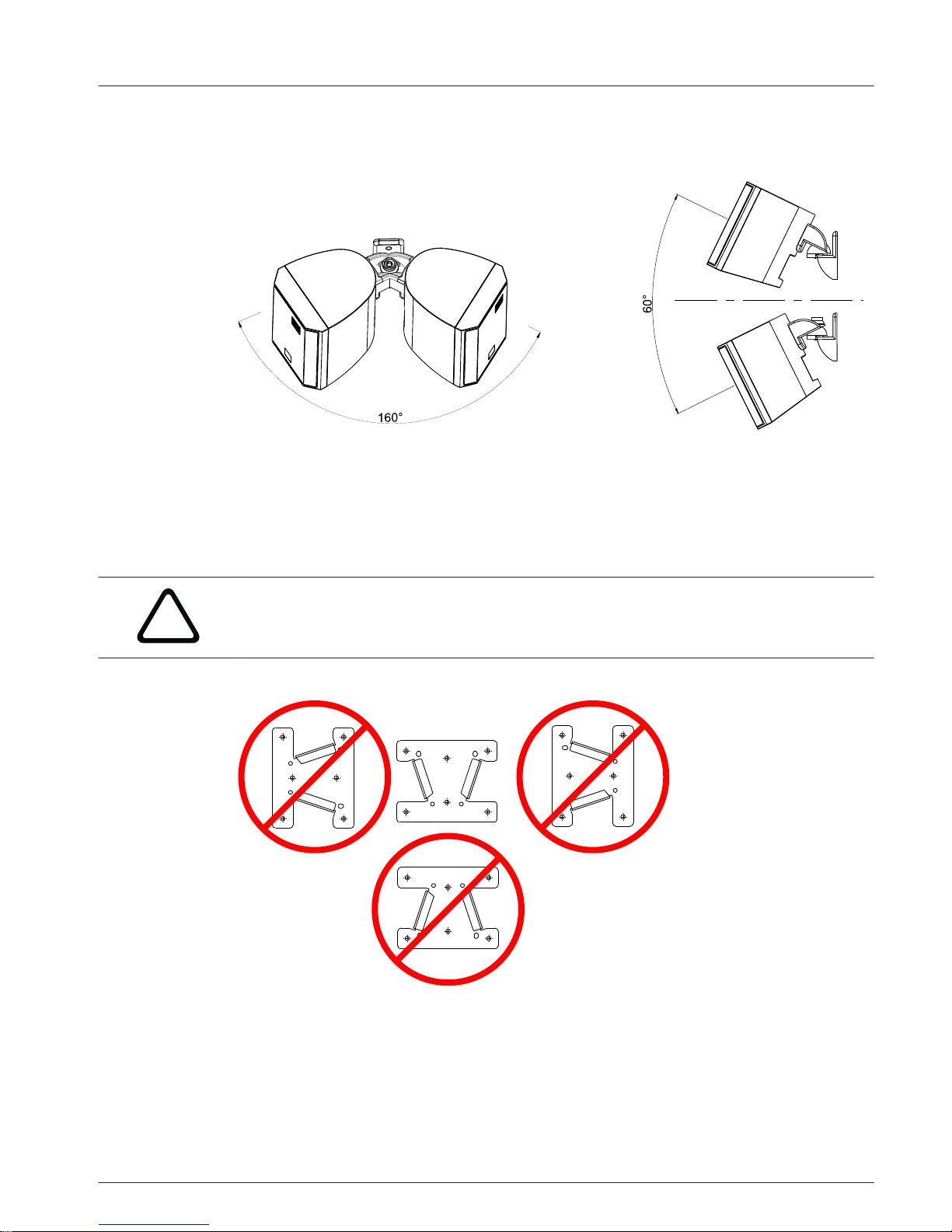
Wall bracket range of motion
The speaker can be adjusted from side to side or up and down.
Figure 4.1: Horizontal range is 160° and the vertical range is 60°.
Surface mount subwoofer installation
For safety, ensure the mounting surface supports more than the weight of the speaker. Use
only industry-accepted fasteners and mounting methods when mounting the wall bracket.
Consult an expert if you are unsure.
!
Caution!
Only mount the wall bracket in the vertical V-shape position.
Do not mount the V-bracket or wall bracket side ways or upside down.
Figure 4.2: Wall bracket correct and incorrect mounting positions
4.2
4.3
en 11
Electro-Voice Installation Manual 2015.02 | 03 | F.01U.310.295
Page 12
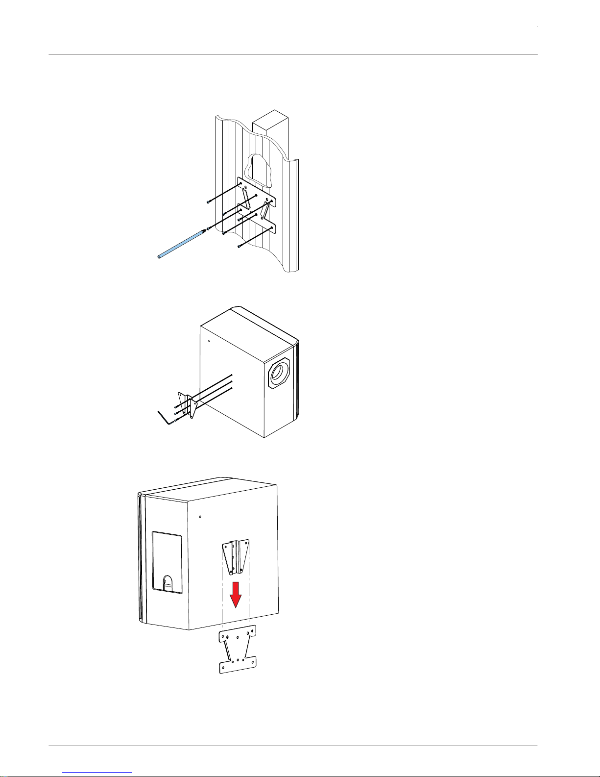
To install the surface mount subwoofer, do the following:
1. Using a Phillips head screwdriver (not supplied), tighten six (6) M5 pan-head screws
(not supplied)
to attach the wall bracket to a secure mounting surface.
2. Using the hex wrench (supplied), tighten the three (3) M6 hex drive pan head screws to
attach the V-bracket.
3. Slide the V-bracket into the wall bracket.
The locking detents engage.
For more information, see Safety, page 4.
EVID Compact Sound Speaker System
2015.02 | 03 | F.01U.310.295 Installation Manual Electro-Voice
Page 13
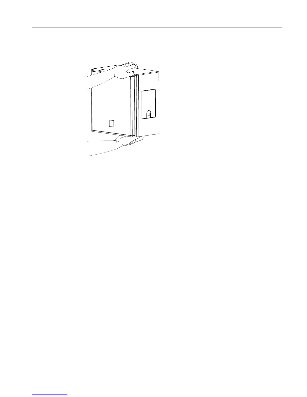
Removing subwoofer from the wall
To remove the subwoofer from the wall, do the following:
1. Pull the subwoofer
slightly out from the wall.
2. Lift the subwoofer up.
The locking detents disengage.
4.4
en 13
Electro-Voice Installation Manual 2015.02 | 03 | F.01U.310.295
Page 14
Wiring
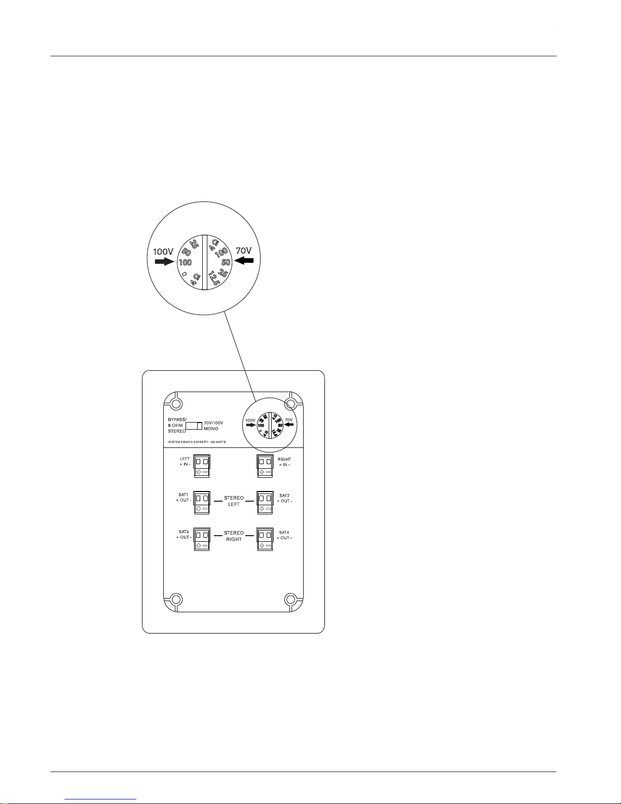
Wattage tap
Prior to wiring your system, select the mode of operation (100V/70V/4 ohm or 8 ohm stereo)
by setting the slider switch to the appropriate setting. Select taps using the rotary switch on
the subwoofer input panel. The power taps are 100 W, 50 W, 25 W, and 12.5 W at 70.7V and
100V, as well as a 4 ohm transformer bypass setting. A guide on the input panel shows which
switch positions to use for the power settings at 70V and 100V.
Figure 5.1: Wattage tap
5
5.1
EVID Compact Sound Speaker System
2015.02 | 03 | F.01U.310.295 Installation Manual Electro-Voice
Page 15
70v/100v/4 ohm Mono
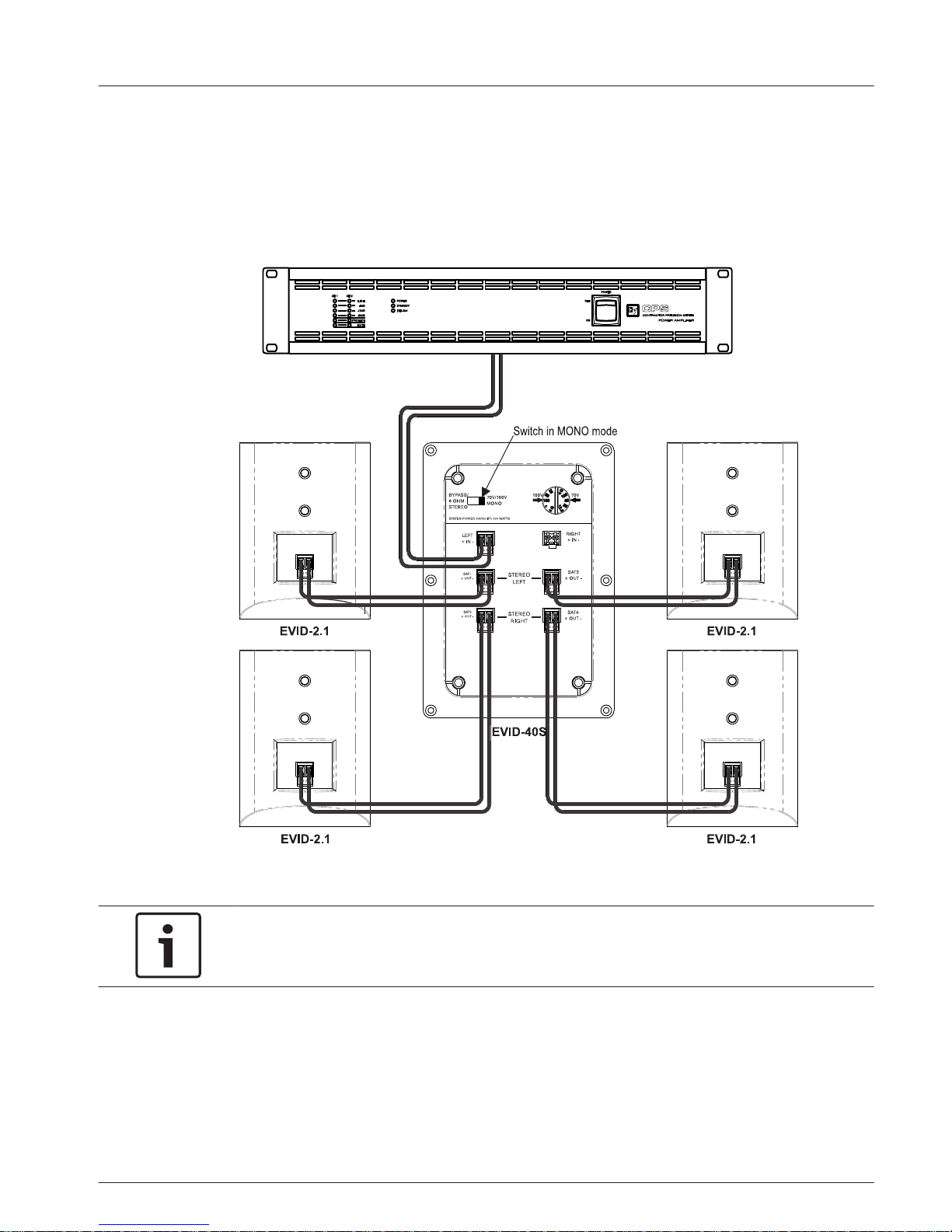
The amplifier and EVID Compact Sound Speaker System
is wired for MONO mode. It is highly
advisable to support the unit while these connections are being made. Connect all wires to
the speaker at the back terminal plate observing proper polarity of the connections. After all
connections are made test the complete system operation.
Notice!
The system is designed for operation with four (4) satellite speakers. Operation with less
than four (4) satellite speakers is not recommended.
5.2
en 15
Electro-Voice Installation Manual 2015.02 | 03 | F.01U.310.295
Page 16
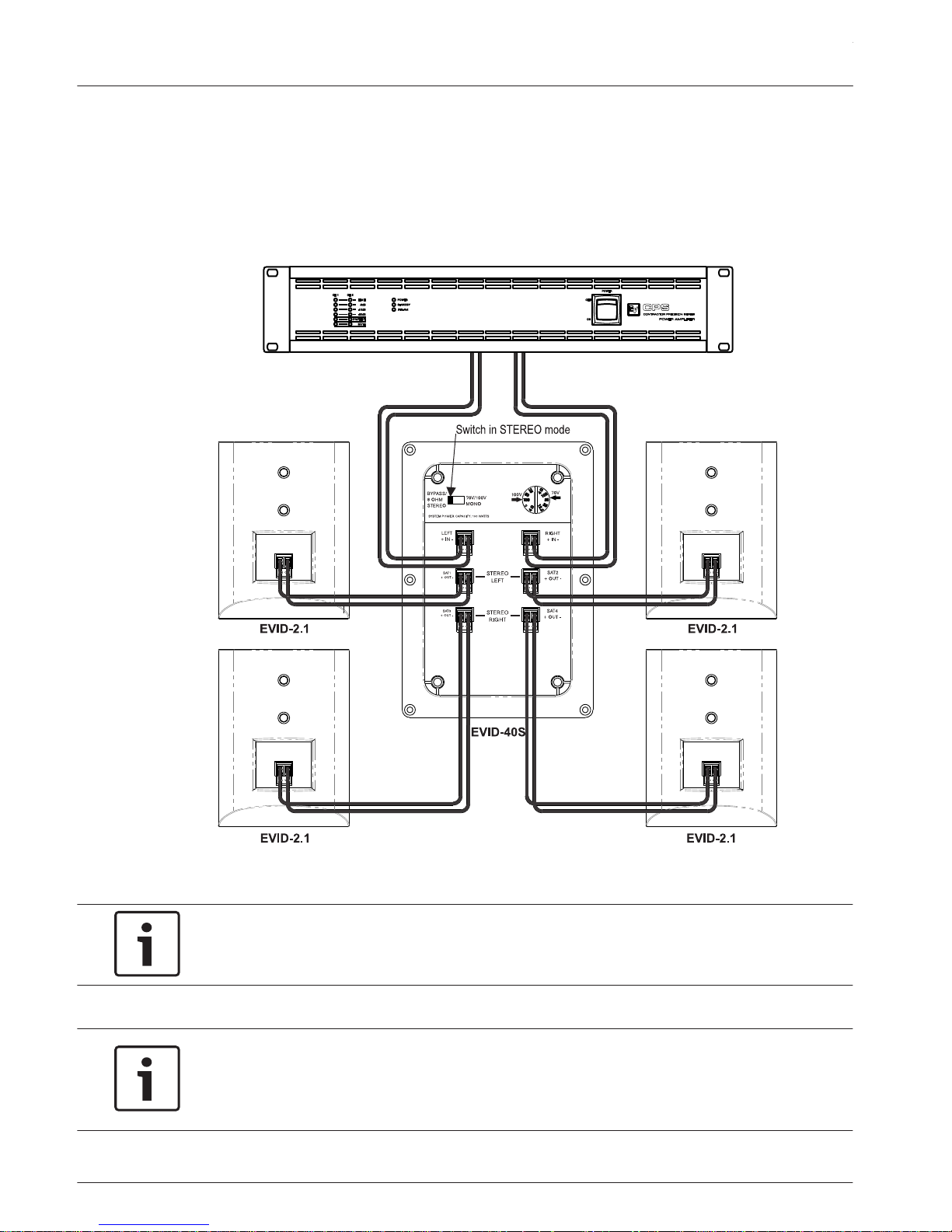
8 ohm Stereo
The amplifier and EVID Compact Sound Speaker System
is wired for STEREO mode. It is highly
advisable to support the unit while these connections are being made. Connect all wires to
the speaker at the back terminal plate observing proper polarity of the connections After all
connections are made test the complete system operation.
Notice!
The system is designed for operation with four (4) satellite speakers. Operation with less
than four (4) satellite speakers is not recommended.
Notice!
A standard low impedance (4/8 ohm) amplifier source is required when operating the unit in
STEREO mode.
100/70v operation is not supported in STEREO mode.
5.3
EVID Compact Sound Speaker System
2015.02 | 03 | F.01U.310.295 Installation Manual Electro-Voice
Page 17

Troubleshooting
Problem Possible Causes Action
No Sound Amplifier Connect a known working test speaker to the amplifier outputs. If
there is no sound, check all electronics are on, the signal routing is
correct, the source is active; the volume is turned up, and so on.
Correct/Repair/Replace as necessary. If there is sound, the problem is
in the wiring.
Wiring Verify you have connected the correct wire pairs to the amplifier. Play
something at low level through the amplifier (for example, from a CD
player or tuner). Connect the test speaker in parallel with the
malfunctioning line. If the sound has gone or is very weak, the line has
a short in it (possibly a severe scrape, pinch, or staple puncture). If
the sound level is normal the wire is open (possibly a cut wire or
missed connection). Using the test speaker, move down the line and
test each connection/junction until you find the problem and correct
it. Observe proper polarity.
Verify you have the inputs and outputs connected to the correct wires.
If the subwoofer input panel is not correctly wired, there will be little
or no sound. Observe proper polarity.
Poor LowFrequency
Response
Speakers Wired Outof-Polarity
When two (2) speakers are connected out of polarity (out of phase),
the low frequencies will cancel each other acoustically. Carefully
observe the wire markings or tracers on your speaker wires. Verify the
amplifier (+) terminal is connected to the red speaker terminals and
the amplifier (-) terminal is connected to the black speaker terminals.
Improperly Wired
Subwoofer Panel
Using a test speaker as described above, verify all amplifier and
speaker wires are connected to their proper terminals with the correct
polarity. Reversing just one (1) set of amplifier wires can cut out all
bass output from the subwoofer.
Intermittent
Output such as,
Crackling or
Distortion
Faulty Connection Check all connections at amplifier and speakers to ensure they are
clean and tight. If the problem persists, it may be in the amplifier or
wiring. See other actions above.
Constant Noise
such as Buzzing,
Hissing, Humming
Defective Amplifier
or other Electronic
Device
If the noise is present but no program material is playing, the likely
cause is the signal chain in the electronics. Evaluate each component
as necessary to isolate the problem.
Poor System
Grounding or
Ground Loop
Check and correct the system grounding, as required.
If these suggestions do not solve your problem, contact your nearest Electro-Voice dealer or
Electro-Voice distributor.
6
en 17
Electro-Voice Installation Manual 2015.02 | 03 | F.01U.310.295
Page 18
Technical data
EVID 2.1 EVID 40S
Frequency Response (-10 dB): 180 Hz - 20 kHz
1
42 Hz - 300 Hz
1
Power Handling: 30 W
2
200 W
2
Sensitivity: 84 dB
1
88 dB
1
Impedance: 16 ohms Dual 8 ohm / mono 4 ohm
Maximum SPL: 100 dB
1
114 db
1
Voice Coverage (H x V): 150° x 150°
3
Omnidirectional
Music Program Coverage (H x V): 100° x 100°
4
Omnidirectional
Transducer: 50 mm (1.97 in) 200 mm (7.87 in)
Bracket Adjustment Range (H x V): 160° x 60° Fixed
Connectors: Phoenix (2-pin) Phoenix (2-pin)
Enclosure: ABS (fire rated) Wood (MDF)
Transformer Taps: NA 100 W, 50 W, 25 W, 12.5 W
Dimensions (H x W x D): 115 mm x 85 mm x 95 mm
(4.53 in x 3.35 in x 3.75 in)
400 mm x 400 mm x 230 mm
(15.75 in x 15.75 in x 9.06 in)
Net Weight: (each) 0.5 kg (1.1 lb) 12.05 kg (26.55 lb)
Shipping Weight: 1 sub and 4 satellites: 18.26 kg (40.25 lb)
Included Accessories: Wall bracket; hex wrench Wall bracket; hex wrench
1. Half space (wall mounting).
2. Long Term Program Rating, 3 dB greater than continuous noise pink noise rating.
3. Average 1 kHz – 4 kHz.
4. Average 1 kHz – 8 kHz.
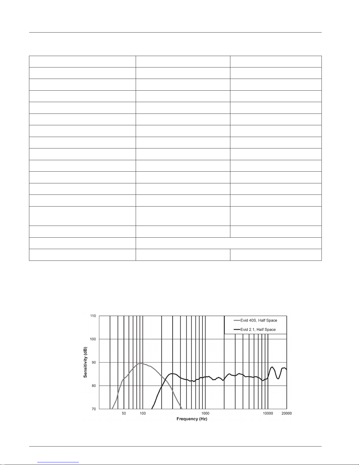
Frequency response
Figure 7.1: EVID-2.1 with EVID-40S frequency response
7
7.1
EVID Compact Sound Speaker System
2015.02 | 03 | F.01U.310.295 Installation Manual Electro-Voice
Page 19

en 19
Electro-Voice Installation Manual 2015.02 | 03 | F.01U.310.295
Page 20

Bosch Security Systems, Inc
12000 Portland Avenue South
Burnsville MN 55337
USA
www.electrovoice.com
© Bosch Security Systems, Inc, 2015
 Loading...