

Page 1
EVF/EVH
User Manual
EVF-1121S
EVF-1151S
EVF-1181S
EVF-2121S
EVF-2151D
EVF-1122S (All Patterns)
EVF-1122D (All Patterns)
EVF-1152S (All Patterns)
EVF-1152D (All Patterns)
EVH-1152S (All Patterns)
EVH-1152D (All Patterns)
Page 2

Table of Contents
Rigging-Safety Warning ...........................................................................................................................................................................................3
1.0 Introduction ........................................................................................................................................................................................................4
1.1 Finishes and Colors Available .........................................................................................................................................................9
1.2 EVF Front-Loaded Series ................................................................................................................................................................9
1.3 EVH Horn-Loaded Series ................................................................................................................................................................9
1.4 Accessories for EVF and EVH Systems .....................................................................................................................................10
2.0 Tool List ......................................................................................................................................................................................................10
3.0 Designing an EVF/EVH Cluster ................................................................................................................................................................. 11
3.1 General Aiming and Placement Guidelines .............................................................................................................................. 11
3.2 Choosing between the EVF Full-Range and EVH Full-Range Systems ............................................................................ 11
3.21 Directivity Break Frequency Defi ned ........................................................................................................................ 11
3.3 More on Coverage Patterns, Multiple Coverage Patterns, the Need for Clusters of
Loudspeakers and How Far a Single Cluster Can “Reach” into a Venue ......................................................................... 12
3.31 Basic Clustering Guidelines ......................................................................................................................................12
3.4 Coverage-Uniformity Target ......................................................................................................................................................... 13
3.5 Multiple-Source Interference in Clusters .................................................................................................................................. 14
3.51 Reducing Multiple-Source Interference .................................................................................................................. 16
4.0 Preparing EVF and EVH Systems for Installation ...................................................................................................................................19
4.1 Recommended Prefl ight Procedures ......................................................................................................................................... 19
4.2 Passive/Biamp Crossover Confi guration .................................................................................................................................. 19
4.3 Rotation of High-Frequency Waveguides (EVF Systems) .................................................................................................... 20
4.4 Rotation of High-Frequency Waveguides and Mid-Frequency Waveguide
Contours (EVH Systems) .............................................................................................................................................................. 20
4.5 Digital Signal Processing .............................................................................................................................................................. 21
4.51 Full-Range Systems in Passive Mode ..................................................................................................................... 21
4.52 Using the EVF-1121S and EVF-1151S Low-Frequency Systems in Full-Range
Clusters that Operate on a Single Power-Amplifi er Channel ............................................................................ 22
4.53 DSP (Digital Signal Processor) Loudspeaker Presets for Biamp Operation .................................................22
5.0 EVF and EVH Rigging System .................................................................................................................................................................... 23
5.1 Introduction ...................................................................................................................................................................................... 23
5.11 The Flying EV-Innovation (EV-I) Loudspeaker System ........................................................................................23
5.12 Important Details that Apply to the VRK and HRK Rigging Kits ....................................................................... 26
5.2 EV-I Rigging Primer ........................................................................................................................................................................ 26
5.21 Anatomy of an EVF or EVH Flying System Using M10 Eyebolts ....................................................................... 27
5.211 Eyebolt Application Warnings ................................................................................................................. 27
5.212 Eyebolt Installation ..................................................................................................................................... 28
5.213 All-Eyebolt Clusters ...................................................................................................................................29
5.22 VRK Kits and Vertically Rigged Clusters ................................................................................................................ 31
5.23 HRK Kits and Horizontally Rigged Clusters ..........................................................................................................32
5.24 Assembly Instructions for VRK and HRK Kits ....................................................................................................... 35
6.0 Rigging-Strength Ratings and Safety Factors .........................................................................................................................................37
6.1 Working Load Limit and Safety-Factor Defi nitions ..................................................................................................................37
6.2 Structural-Rating Overview .......................................................................................................................................................... 38
6.3 All-Eyebolt Structural Ratings ...................................................................................................................................................... 39
6.31 Working Load Limits for Eyebolts ............................................................................................................................. 40
6.32 Suspension-Line Angles ............................................................................................................................................. 41
6.33 Left-to-Right All-Eyebolt Cluster Angles ................................................................................................................ 41
6.4 VRK Rigging Structural Ratings for Vertical Clusters ............................................................................................................ 42
6.41 Working Load Limits for Eyebolts used with VRK Vertical Rigging Kits .......................................................... 44
6.42 Left-to-Right Vertical Cluster Angles ....................................................................................................................... 45
2
Electro-Voice EVF/EVH User Manual
Page 3

Table of Contents (cont.)
6.5 HRK Rigging Structural Ratings for Horizontal Clusters ......................................................................................................46
6.51 Using Tie Plates as Main Load-Bearing Suspension ............................................................................................47
6.52 Suspension-Line Angles for HRK Kits .................................................................................................................... 48
6.53 Symmetry for Horizontal Clusters using HRK Kits ...............................................................................................49
6.54 Inner Connection Points .............................................................................................................................................50
6.55 Left-to-Right Horizontal Cluster Angles .................................................................................................................. 50
6.6 Ratings for Outdoor Applications with Wind Loading ........................................................................................................... 51
6.7 Electro-Voice Structural-Analysis Procedures ......................................................................................................................... 51
7.0 Rigging Inspection and Precautions ........................................................................................................................................................... 52
8.0 Installation Instructions TK150.. .................................................................................................................................................................. 53
8.1 Transformer Ratings .......................................................................................................................................................................54
8.2 Approvals and Certifi cations ........................................................................................................................................................ 54
9.0 Refrences......................................................................................................................................................................................................... 55
9.1 Rigging (Printed) ............................................................................................................................................................................. 55
9.2 Mechanical Engineering (Printed) ............................................................................................................................................... 55
9.3 Rigging (Websites) ........................................................................................................................................................................55
Rigging-Safety Warning
This document details general rigging practices appropriate to the entertainment industry, as they would apply to the rigging
of Electro-Voice EVF and EVH loudspeaker systems. It is intended to familiarize the reader with standard rigging hardware and
techniques for suspending EVF and EVH loudspeaker systems overhead. Only persons with the knowledge of proper hardware
and safe rigging techniques should attempt to suspend any sound systems overhead. Prior to suspending any
Electro-Voice EVF and EVH loudspeaker systems overhead, it is essential that the user be familiar with the strength
ratings, rigging techniques and special safety considerations outlined in this manual. The rigging techniques and practices
recommended in this manual are, of necessity, in general terms to accommodate the many variations in loudspeaker clusters
and rigging confi gurations. As such, the user is expressly responsible for the safety of all specifi c EVF and EVH
loudspeaker cluster designs and rigging confi gurations as implemented in practice.
All the general rigging material contained in this manual is based on the best available engineering information concerning
materials and practices, as commonly recognized in the United States, and is believed to be accurate at the time of original
printing. As such, the information may not be directly applicable in other countries. Furthermore, the regulations and
requirements governing rigging hardware and practices may be superseded by local regulations. It is the responsibility of the
user to ensure that any Electro-Voice loudspeaker system is suspended overhead in accordance with all current federal, state
and local regulations.
All specifi c material concerning the strength ratings, rigging techniques and safety considerations for the EVF and EVH
loudspeaker systems is based on the best available engineering information concerning the use and limitations of the
products. Electro-Voice continually engages in testing, research and development of its loudspeaker products. As a result, the
specifi cations are subject to change without notice. It is the responsibility of the user to ensure that any
Electro-Voice loudspeaker system is suspended overhead in accordance with the strength ratings, rigging techniques and
safety considerations given in this document and any manual update notices. All non-Electro-Voice associated hardware items
necessary to rig a complete EVF and EVH loudspeaker cluster (chain hoists, building or tower supports and miscellaneous
mechanical components) are the responsibility of others.
Electro-Voice
June 2010
Electro-Voice EVF/EVH User Manual
3
Page 4
1.0 Introduction
The Electro-Voice EVF series is a group of compact two-way front-loaded full-range systems, available
with 12- or 15-inch woofers, augmented by low-frequency and subwoofer systems. EVF full-range systems are available in two versions. The “S” versions employ 400-watt SMX low-frequency transducers
and the ND2B medium-format, 1.4-inch exit/2-inch diaphragm compression driver. The “D” versions employ 500-watt DVX-A low-frequency transducers and the DH7N large-format, 1.4-inch exit/3-inch diaphragm compression driver. Both compression drivers have neodymium magnetic structures. In general,
the premium components in the “D” versions provide lower distortion and reduced power compression.
The EVH series is a group of larger two-way horn-loaded full-range systems. Both the “S” and “D” EVH
versions use SMX low-frequency transducers. The “D” versions substitute the DH7N large-format compression driver for the ND2B medium-format driver.
All full-range systems utilize high-order crossover networks that seamlessly integrate the low-frequency
transducers with the high-frequency compression drivers, providing very low distortion and excellent frequency response.
The EVF/EVH systems have many threaded rigging points that can be used with the supplied eyebolt kits
or optional suspension kits to easily create a number of horizontal or vertical cluster confi gurations. All
enclosures in their normal orientations (long axis vertical) share the same height, just over 30 inches (762
mm), promoting attractive clusters. Six coverage patterns, all rotatable, are available in each family, as
shown in Table 1a. The EVF-1121S and EVF-1151S low-frequency systems have integral low-pass fi lters
that allow paralleling them with up to two full-range systems, offering a cost-effective way to augment the
low-frequency output of EVF full-range systems.
Horn Pattern: 40° x 30° 60° x 40° 60° x 60° 90° x 40° 90° x 60° 90° x 90° 120° x 60°
EVF 12-inch
EVF 15-inch
EVH
Coverage patterns available in the EVF and EVH series (all rotatable)
The model number scheme denotes the number of woofers, the diameter of the woofers, the number of
band passes in the system, the woofer series used and, following a forward slash, the coverage pattern.
An example is the EVF-1122S/96, which has a single SMX series 12-inch woofer in a two-way confi guration and a 90° x 60° pattern. Another example is the EVF-1181S subwoofer, which has a single EVS-18S
18-inch woofer in a “one way” confi guration and without a specifi c coverage pattern (essentially omnidirectional in the very-low-frequency range in which it is usually operated).
4
••••••
••••••
••••••
Table 1a:
Electro-Voice EVF/EVH User Manual
Page 5
1.0 Introduction (cont.)
Model Name
(As Shown)
Model Name
(Separated)
Description
EVF - 1 12 2 S / 96
Loudspeaker
Family/Series
(EVF Series)
EVF-1122S/96 (example)
Number of
Woofers
(1 Woofer)
Woofer
Diameter
(12-inch)
Number of
Band Passes
(Two-Way)
Woofer
Series Used
(SMX Series)
Coverage
Pattern
(90° x 60°)
Table 1b:
Model number scheme, showing the meaning of each individual model number
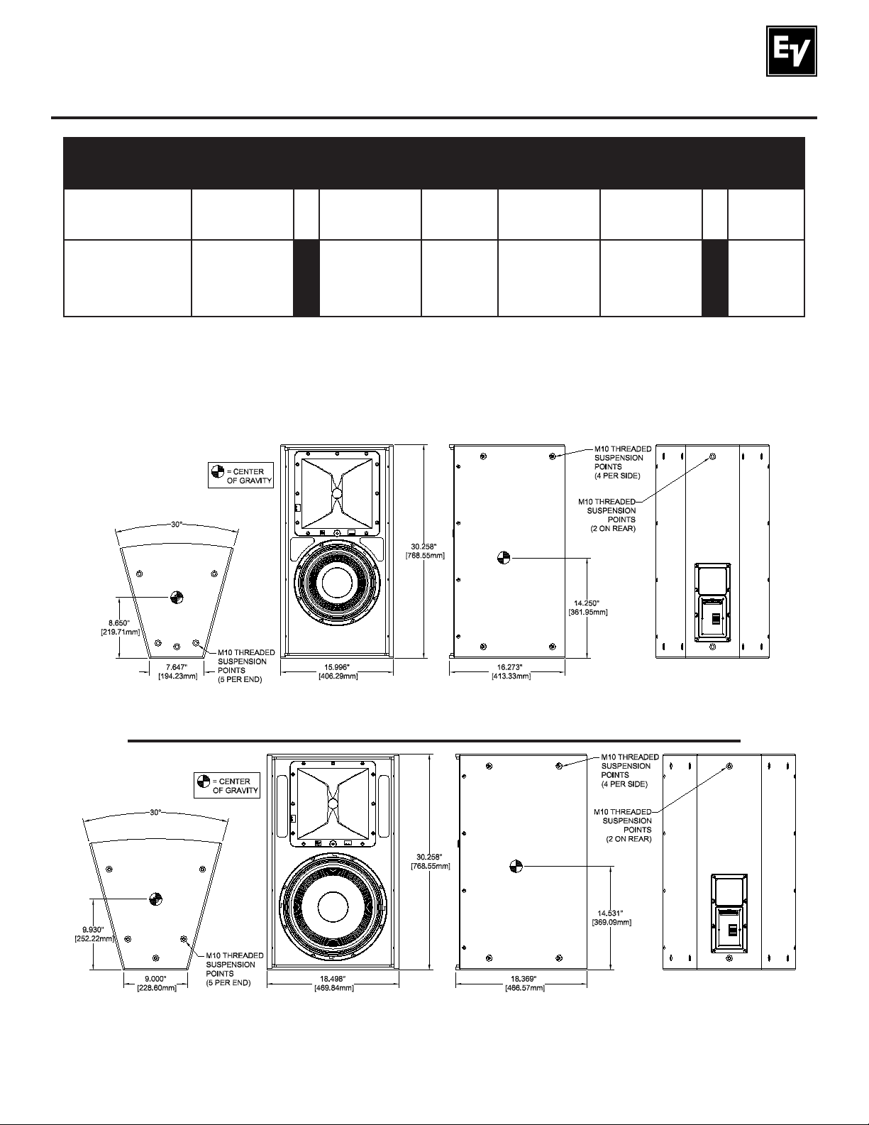
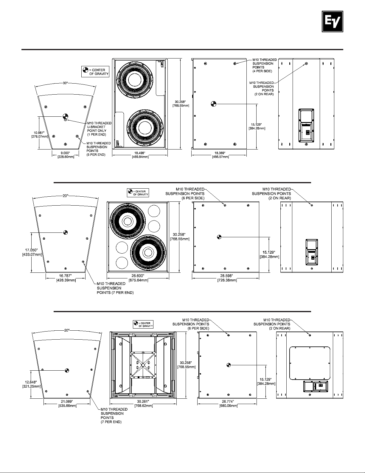
Typical EVF and EVH systems are shown in Figure 1, with key dimensions, suspension points, weights
and centers-of-gravity. Engineering data sheets for each model, containing full specifi cations and dimensional drawings, are shipped with each loudspeaker and are downloadable from the Electro-Voice Web
site (www.electrovoice.com).
“S” System Weight -
60.0 lb (27.2 kg)
“D” System Weight -
65.5 lb (29.7 kg)
Front ViewEnd View Side View Rear View
Figure 1a:
Key dimensions, suspension points, weight, and center-of-gravity for EVF-1122 (all coverage patterns)
“S” System Weight -
70.1 lb (31.8 kg)
“D” System Weight -
75.7 lb (34.4 kg)
Front ViewEnd View Side View Rear View
Figure 1b:
Key dimensions, suspension points, weight, and center-of-gravity for EVF-1152 (all coverage patterns)
Electro-Voice EVF/EVH User Manual 5
Page 6
1.0 Introduction (cont.)
System Weight -
57.7 lb (26.2 kg)
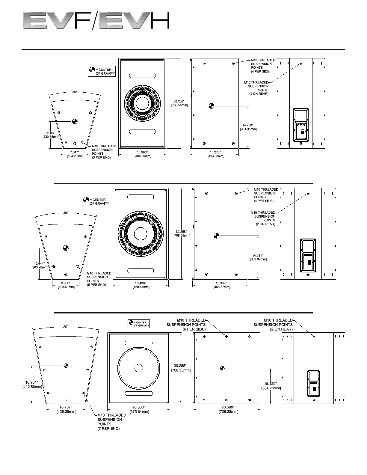
Front ViewEnd View Side View Rear View
Key dimensions, suspension points, weight, and center-of-gravity for EVF-1121S
System Weight -
62.6 lb (28.4 kg)
Figure 1c:
System Weight -
101.2 lb (46.0 kg)
6
Front ViewEnd View Side View Rear View
Figure 1d:
Key dimensions, suspension points, weight, and center-of-gravity for EVF-1151S
Front ViewEnd View Side View Rear View
Figure 1e:
Key dimensions, suspension points, weight, and center-of-gravity for EVF-1181S
Electro-Voice EVF/EVH User Manual
Page 7
1.0 Introduction (cont.)
System Weight -
82.4 lb (37.4 kg)
Front ViewEnd View Side View Rear View
Key dimensions, suspension points, weight, and center-of-gravity for EVF-2121S
System Weight -
117.0 lb (53.1 kg)
Figure 1f:
Front ViewEnd View Side View Rear View
Figure 1g:
Key dimensions, suspension points, weight, and center-of-gravity for EVF-2151D
“S” System Weight -
143.0 lb (64.9 kg)
“D” System Weight -
145.5 lb (66.1 kg)
Front ViewEnd View Side View Rear View
Figure 1h:
Key dimensions, suspension points, weight, and center-of-gravity for EVH-1152 (all coverage patterns)
Electro-Voice EVF/EVH User Manual
7
Page 8
1.0 Introduction (cont.)
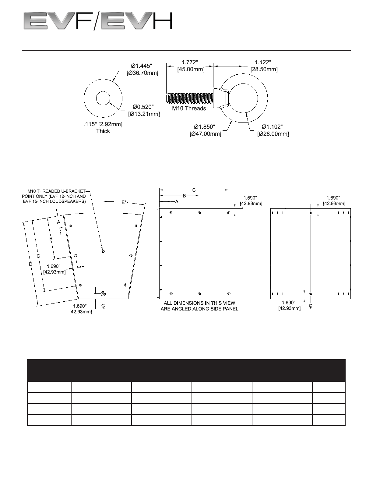
Washer (x4) Eyebolt (x4)
Key dimensions for washers and eyebolts included with each loudspeaker
Figure 1g:
End View Side View Rear View
Figure 1h:
Key suspension point dimensions for EVF or EVH loudspeakers as indicated in table below
Dimension: A B C D E°
EVF 12-inch 4.176” [106.07mm] 14.301” [363.24mm] N/A 16.129” [409.67mm] 15°
EVF 15-inch 4.176” [106.07mm] 14.301” [363.24mm] N/A 18.353” [466.16mm] 15°
EVF Subs 3.957” [100.50mm] 13.889” [352.77mm] 23.857” [605.97mm] 28.255” [717.68mm] 10°
EVH 3.957” [100.50mm] 13.889” [352.77mm] 23.857” [605.97mm] 26.409” [670.79mm] 10°
Table 2:
Key suspension point dimensions as shown in fi gure above
8
Electro-Voice EVF/EVH User Manual
Page 9

1.0 Introduction (cont.)
1.1 Finishes and Colors Available
The standard EVF/EVH indoor versions are fi nished in tough EVCoat. In addition, all models are available
in two levels of weather resistance, indicated by letters following the coverage-pattern numbers. The FG
versions, e.g., EVF-1152S/64-FGB, are designed for full weather exposure and feature a fi berglassfi nished enclosure, stainless-steel hydrophobic grille and the CDG dual-gland-nut input-panel cover. The
PI versions, e.g., EVF-1152S/64-PIW, are rated for indirect outdoor exposure only in protected areas,
such as under a roof overhang, and feature a stainless-steel hydrophobic grille and CDG
dual-gland-nut input-panel cover on an enclosure fi nished in standard EVCoat. External fasteners on all
systems are stainless steel.
All EVF and EVH systems are available in black or white. Black is indicated by BLK or B at the very end of
the complete model number and white is indicated by WHT or W at the very end of the complete model
number, e.g., EVF-1152/94-BLK and EVF-1152S/94-PIW.
1.2 EVF Front-Loaded Series
Note that engineering data sheets with complete specifi cations are packed with each system and
downloadable at www.electrovoice.com.
EVF-1122S/64, EVF-1122S/66, EVF-1122S/94, EVF-1122S/96, EVF-1122S/99, EVF-1122S/126,
EVF-1122D/64, EVF-1122D/66, EVF-1122D/94, EVF-1122D/96, EVF-1122D/99, EVF-1122D/126:
two-way 12-inch full-range systems with six different rotatable waveguides ranging from 60° x 40° to
120° by 60°, as detailed in Table 1.
EVF-1152S/43, EVF-1152S/64, EVF-1152S/66, EVF-1152S/94, EVF-1152S/96, EVF-1152S/99,
EVF-1152D/43, EVF-1152D/64, EVF-1152D/66, EVF-1152D/94, EVF-1152D/96, EVF-1152D/99:
two-way 15-inch full-range systems with six different rotatable waveguides ranging from 40° x 30° to
90° by 90°, as detailed in Table 1.
EVF-1121S: 12-inch low-frequency system.
EVF-1151S: 15-inch low-frequency system.
EVF-1181S: 18-inch subwoofer system.
EVF-2121S: Dual 12-inch low-frequency system.
EVF-2151D: Dual 15-inch subwoofer system.
1.3 EVH Horn-Loaded Series
Note that engineering data sheets with complete specifi cations are packed with each system and
downloadable at www.electrovoice.com.
EVH-1152S/43, EVH-1152S/64, EVH-1152S/66, EVH-1152S/94, EVH-1152S/96, EVH-1152S/99,
EVH-1152D/43, EVH-1152D/64, EVH-1152D/66, EVH-1152D/94, EVH-1152D/96, EVH-1152D/99:
two-way 15-inch full-range systems with six different rotatable high-frequency waveguides ranging from
40° x 30° to 90° x 90° and mid-frequency waveguide contours, as detailed in Table 1.
Electro-Voice EVF/EVH User Manual
9
Page 10

1.0 Introduction (cont.)
1.4 Accessories for EVF and EVH Systems
Note that some accessories are supplied with certain system versions, as noted.
CDG: optional dual-gland-nut input-panel cover to protect the input connections from water. Note that
this cover is supplied with the weather-resistant versions.
CSG: optional single-gland-nut input-panel cover to protect the input connections from water.
CDNL4: optional input-panel cover equipped with dual Neutrik Speakon® NL4M connectors, providing a
quick-disconnect alternative to the standard Phoenix screw-terminal input connectors.
HRK and VRK: a series of horizontal (HRK) and vertical (VRK) rigging kits that accommodate a number
of horizontal and vertical system aiming angles. See section 5.0 EVF and EVH Rigging System for details.
TK-150: optional 70.7/100-volt transformer kit mounts on the inside of the EVF and EVH input panels,
offering 37.5, 75 and 150 watts at 70.7 volts and 75 and 150 watts at 100 volts. Installation instructions
come with the TK-150.
EVF-UB: optional U-bracket kit for mounting single EVF full-range and low-frequency (not subwoofer)
systems to a wall or ceiling. Installation instructions come with the EVF-UB.
EVI-M10K: optional eyebolt kit, consisting of four M10 shoulder eyebolts and four fender washers, used
when additional eyebolts are needed to suspend loudspeakers. See section 6.3 for details. One EVIM10K eyebolt kit is supplied with each loudspeaker system.
EVI-AC: optional access card which allows diagnostic access to the transducers and protection circuitry
inside the enclosure. Use of this accessory does not require any disassembly or disconnections beyond
removal of the plug-in switch card.
2.0 Tool List
Listed below are the tools required to prepare EVF and EVH systems for installation:
1. 3/16-inch fl at-blade screwdriver (for attaching signal wires to input-panel connectors).
2. Phillips #2 screwdriver (for grille removal to rotate waveguides, removal of high-frequency
waveguides for rotation, and removal of input panel to install the optional TK-150
70.7/100-volt transformer).
3. 4-mm Allen (hex) wrench (for removal and reorientation of the EVH hard foam
mid-frequency waveguide contours to rotate the mid-frequency coverage pattern).
4. 6-mm Allen (hex) wrench (for working with all rigging points).
10
Electro-Voice EVF/EVH User Manual
Page 11

3.0 Designing an EVF/EVH Cluster
3.1 General Aiming and Placement Guidelines
Loudspeakers should be “pointed at the people” and away from refl ective room surfaces. Since people
are excellent absorbers of sound and room surfaces are often not, this practice insures not only that the
audience will receive the high frequencies necessary for good voice intelligibility and musical clarity but
also that the refl ective surfaces do not energize the room with intelligibility-robbing reverberation.
Loudspeakers for sound reinforcement are usually located high above a stage or platform and aimed
down and out into the audience. This minimizes the difference between the longest throws to the rear of
a venue and the shortest throws to the front rows, promoting coverage uniformity. Note that the typical
portable loudspeaker on a short, 6-foot stand cannot duplicate such uniformity since the distant seats are
so much farther away than the front rows. The direct sound from a loudspeaker drops 6 dB every time the
distance from it doubles, according to the formula:
Level loss (dB) = 20log10(closest distance/farthest distance).
See comments on the audibility of different dB differences in section 3.4 Coverage-Uniformity Target.
3.2 Choosing between the EVF Full-Range and the EVH Full-Range Systems
When the reverberation time of a room (formally called T60 and the time it takes sound, once the source
has stopped, to decay by 60 dB) exceeds 2-2.5 seconds at mid frequencies, the horn-loaded EVH series
should be used. The EVH’s low-frequency horn mouth is large enough to control the rated coverage
pattern down to 500 Hz, which promotes clarity by keeping more sound off of refl ective surfaces than can
the smaller, 12-inch-square horns and direct-radiating woofers of the EVF series. This concept is explored
in more detail below.
3.21 Directivity Break Frequency Defi ned
Below a certain frequency, the mouth size of a waveguide is no longer large enough to maintain the
nominal coverage angle and the coverage angle gets wider and wider as frequency is decreased. The
frequency at which this occurs is called the “directivity break frequency” (fb) and is inversely proportional
to the size of the waveguide mouth and the nominal coverage angle of the waveguide. The directivity break
frequency can be approximated by the following formula:
f
(Hz) = 1,000,000/[angle (degrees) x dimension (inches)].
b
Electro-Voice EVF/EVH User Manual
11
Page 12

3.0 Designing an EVF/EVH Cluster (cont.)
3.3 More on Coverage Patterns, Multiple Coverage Patterns, the Need for Clusters of Loud-
speakers and How Far a Single Cluster Can “Reach” into a Venue
The coverage patterns or angles mentioned previously are defi ned where loudspeaker output is 6 dB
down from maximum, usually on-axis level. In order to help cover only the absorptive audience with sound,
given different trim heights and the wide variety of venue shapes, the EVF and EVH series are offered in
the many coverage patterns listed in Table 1 (above). Even with this wide choice, it is relatively unlikely that
a single loudspeaker will cover the audience uniformly. Therefore, two or more loudspeakers are often assembled into clusters and aimed in different directions in order to reach the entire audience.
3.31 Basic Clustering Guidelines
The aiming angles of systems in a cluster are related not only to room geometry but also to the particular
coverage patterns selected. A rough design can be based on the plan and elevation views of a room, representing the loudspeakers by the angles of their horizontal and vertical coverage patterns, e.g., 60° x 40°.
A wide or “short throw” coverage pattern, such as 120° x 60°, is good for aiming down into the front rows
of a rectangular venue to reach all of the seats left to right. Narrower patterns, such as 60° x 40° and
40° x 30°, are appropriate as “long throw” devices that send sound to the rear of the audience without
also “blasting out” the front rows.
Sophisticated software is also available, which allows the designer to build a room model and place and
aim loudspeakers within it, assessing the uniformity of coverage. An example is EASE 4.2 (Enhanced
Acoustic Simulator for Engineers), developed by Acoustic Design Ahnert (www.ada-acousticdesign.
de). EASE is available from the Bosch Communications Systems/Electro-Voice technical support group;
specifi c contact information can be found at www.electrovoice.com. EASE loudspeaker data for EVF and
EVH systems may be downloaded at www.electrovoice.com.
A common practice is to widen the horizontal coverage of a single loudspeaker by placing two systems
side by side and aiming them in such a way that their horizontal patterns do not overlap. Individually, each
system will be 6 dB down at the overlap point. Together at the overlap point, they will sum coherently to
the 0-dB on-axis level. A specifi c example is two 60° horizontal systems clustered together with their axes
placed 60° apart.
If these two systems are “underlapped,” with, say, their axes 75° apart, the overall coverage angle will be
wider but the level near the array axis will drop. If the two systems are overlapped to any great degree,
e.g., their axes only 45° apart, the overall coverage angle will be reduced and the interference discussed
in section 3.5 Multiple-Source Interference in Clusters will be worsened.
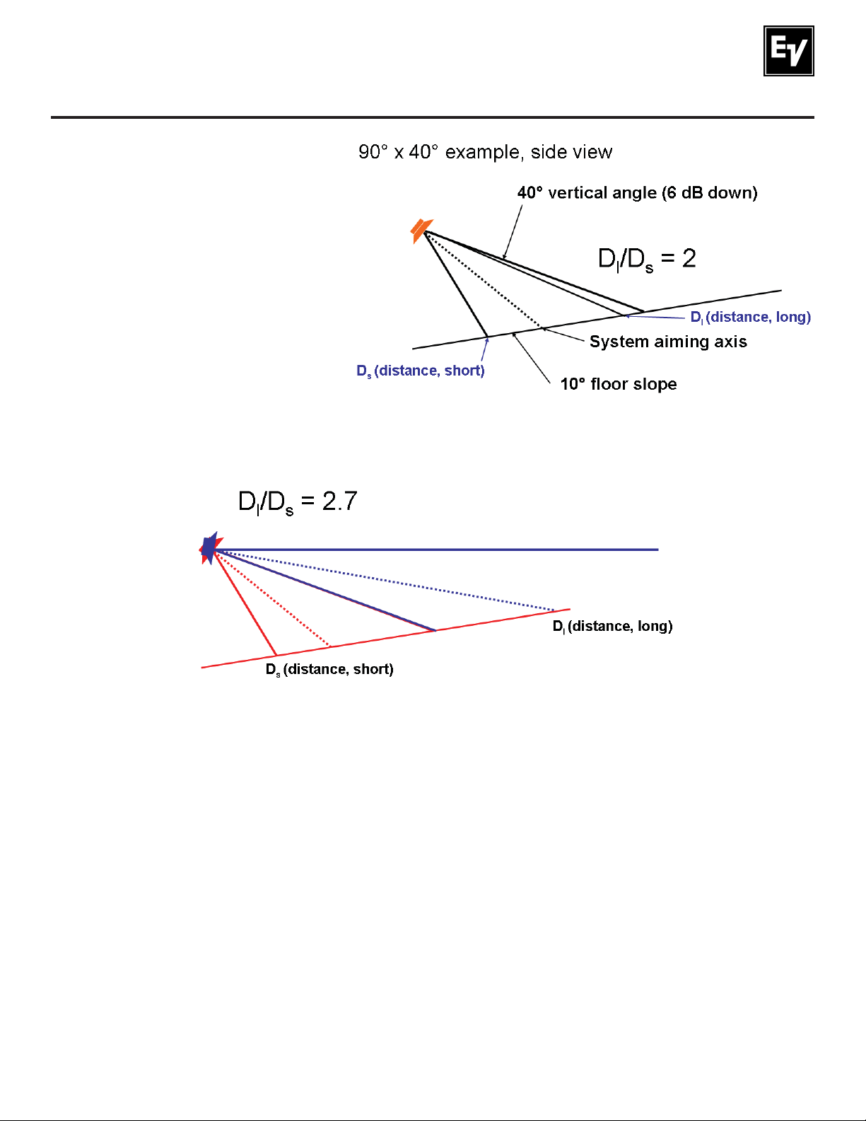
The degree to which long-throw devices can extend the region of uniform coverage is limited. A single
loudspeaker will typically “reach” to the rear a distance that is about twice that of the distance to the closest front row. See Figure 2.
12
Electro-Voice EVF/EVH User Manual
Page 13
3.0 Designing an EVF/EVH Cluster (cont.)
Figure 2:
Typical “reach” of a single loudspeaker
into a venue (DI ) in order to maintain
the desired ±3 dB coverage is about
two times the distance to the closest
seats (DS )
Adding a long-throw device will typically extend this reach to about three times the closest distance. See
Figure 3.
Figure 3:
Adding a long-throw device extends the reach to about three times the distance to the closest seat
For reaches beyond this, loudspeakers can be suspended over the audience, with their signal delayed
with respect to the front or source loudspeakers so that the sound image will appear to come from the
front of the room. The details of these design tips are beyond the scope of this manual and should be left
to experienced design personnel.
3.4 Coverage-Uniformity Target
A good uniformity target is ±3 dB throughout the audience area, particularly in the 2,000- and 4,000-Hz
octave bands, the bands most important for intelligibility. Such coverage should also be achieved in the
8,000-Hz band, important for “sparkle.” As a reference, a 1-dB level difference is nearly imperceptible, a
3-dB difference is noticeable but not a large change, a 6-dB change is clearly noticeable and a 10-dB
change is twice or half as loud. The ±3-dB uniformity target is related to these perceptual differences.
Electro-Voice EVF/EVH User Manual 13
Page 14
3.0 Designing an EVF/EVH Cluster (cont.)
3.5 Multiple-Source Interference in Clusters
Whenever two or more sources serve a single venue, some seats will receive strong signals from multiple
sources. Consider two EVF-1122S/64 60° x 40° systems clustered side by side with their axes 60° apart
to form a 120° x 40° cluster. If these systems maintained their rated coverage patterns into the lowfrequency range, there would be essentially no interference. But the 12-inch-square waveguides used in
the EVF series will begin to “balloon out” at about 2 kHz and below, an effect discussed in Section 3.21
Directivity Break Frequency Defi ned, above.
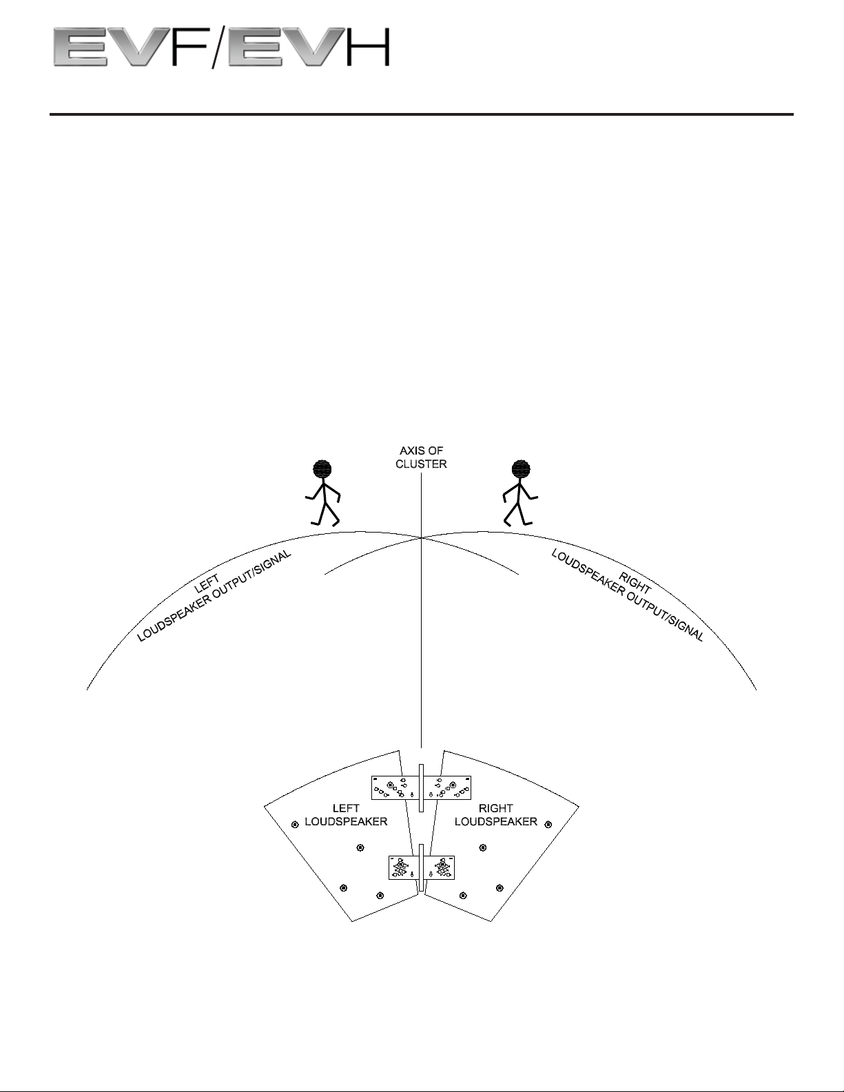
On the axis of the cluster, the output of both systems sums perfectly, since the listener is equidistant from
each system and the output of both reaches the listener at the same time. This is the axis-of-cluster line
shown in Figure 4. If the listener moves to the left (as viewed in the fi gure), the left loudspeaker will be
closer and the sound will arrive sooner. At some angle and at some frequency, the time difference will be
equivalent to reversing the polarity of one signal, causing a complete cancellation of cluster output at that
frequency.
Figure 4:
The two loudspeaker sources sum perfectly only on the axis of the cluster (as shown);
to the left and right of this axis, distance differences produce arrival-time differences
that cause cancellation of some frequencies (see text for more details)
Electro-Voice EVF/EVH User Manual14
Page 15
3.0 Designing an EVF/EVH Cluster (cont.)
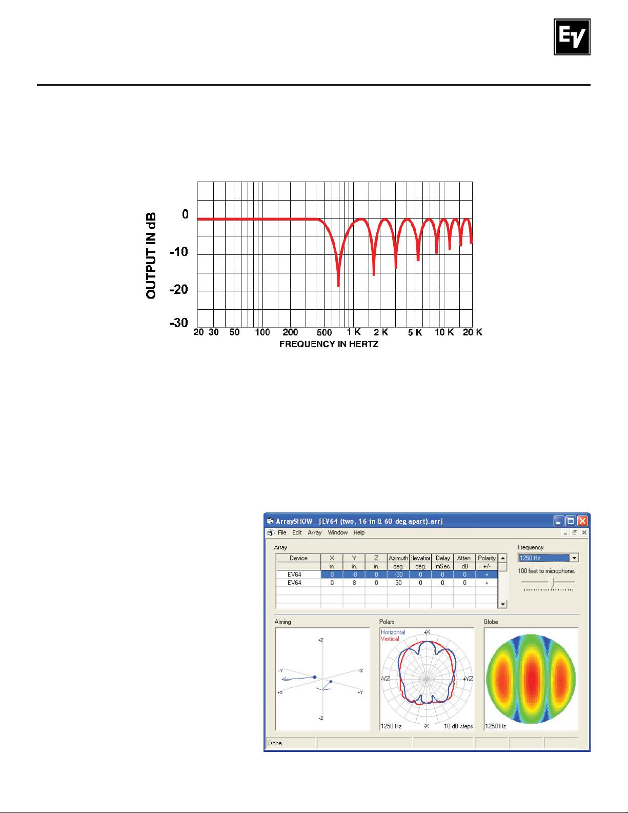
This effect is shown in the frequency-response of Figure 5. Given the dimensions of the typical compact
loudspeaker systems and when they are clustered in close proximity to one another, the fi rst several
interference nulls occur right in the middle of the vocal range. A frequency response with these evermore-closely spaced nulls is known as a “comb fi lter” response, after the visual appearance of the
response.
NORMALIZED
Figure 5:
Typical response off the array axis of the two loudspeakers shown in Figure 4,
showing cancellations due to arrival-time differences
If one of the null frequencies is chosen and the horizontal polar response is measured, the result is shaped
like the blue polar response in the center lower graph of Figure 6. In this view, the cluster axis points up
(+X). Full output is achieved on this axis, since both signals arrive at the same time. But there are off-axis
problems. While the overall coverage of the cluster is about 120° (6 dB down), two deep nulls occur at
about 20° on either side of the cluster axis.
Figure 6:
Horizontal polar response (blue center
plot) of two closely clustered 60° x 40°
loudspeakers aimed 60° apart, showing
the off-axis nulls at 1,250 Hz caused by
multiple-source interference
(see text for more details)
Electro-Voice EVF/EVH User Manual 15
Page 16
3.0 Designing an EVF/EVH Cluster (cont.)
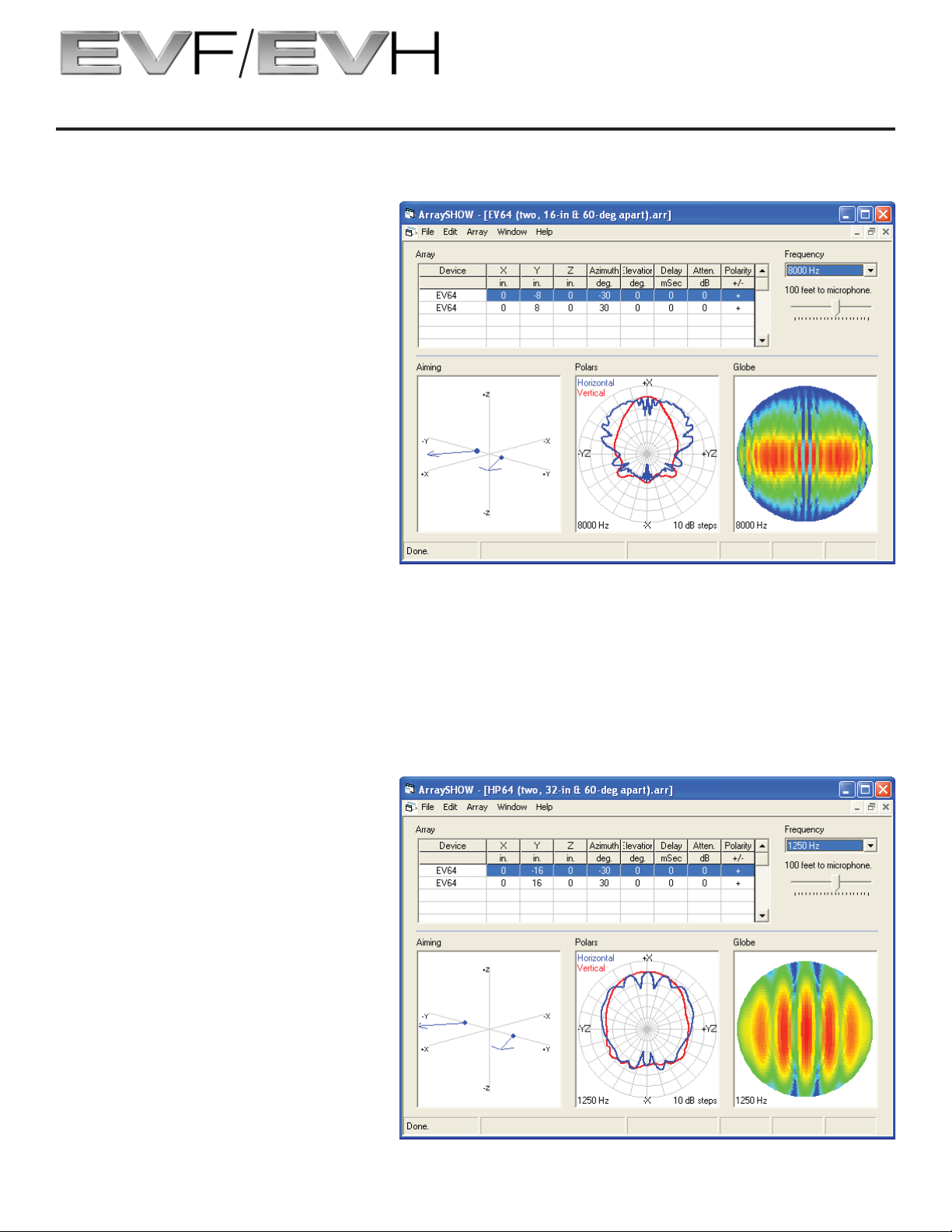
At higher frequencies, the interference patterns become more densely packed, which essentially eliminates their audibility. Figure 7 shows this effect at 8,000 Hz.
Figure 7:
Horizontal polar response (blue center
plot) of two closely clustered 60° x 40°
loudspeakers aimed 60° apart, showing
multiple, densely packed off-axis nulls
at 8,000 Hz caused by multiple-source
interference (see text for more details)
3.51 Reducing Multiple-Source Interference
Multiple-source interference cannot be eliminated but it can be substantially reduced. Systems which
have radiating devices large enough to hold their rated coverage angles down to relatively low frequencies, such as the horn-loaded EVH series that hold their coverage angles down to 500 Hz, will exhibit
less interference in clusters. Also, doubling the distance between the two systems of Figure 8 produces
multiple interference nulls which are more densely packed than those of Figure 6, reducing the audibility of
the interference.
Figure 8:
Horizontal polar response (blue cen-
ter plot) of two 60° x 40° loudspeakers
aimed 60° apart but with double the
distance between grille centers compared
to Figures 6 and 7, showing the more
densely packed 1,250-Hz off-axis nulls
caused by multiple-source interference
(see text for more details)
Electro-Voice EVF/EVH User Manual16
Page 17
3.0 Designing an EVF/EVH Cluster (cont.)
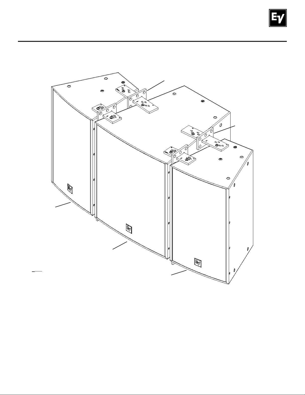
One clustering technique that accomplishes this separation without putting a physical space between two
full-range systems is putting a low-frequency or subwoofer system between two full-range systems. Such
a cluster is shown in Figure 9, assembled with the optional HRK rigging kits.
HRK-2 Kit
(Sold Separately)
HRK-2 Kit
(Sold Separately)
EVF Full-Range
System
EVF Subwoofer
Note: Loudspeakers
are non-specifi c and
shown as an example.
EVF Full-Range
System
Figure 9:
A way of separating two full-range loudspeakers to reduce the audibility of multiple-source interference
by separating them with a subwoofer (see text for more details)
Electro-Voice EVF/EVH User Manual 17
Page 18
3.0 Designing an EVF/EVH Cluster (cont.)
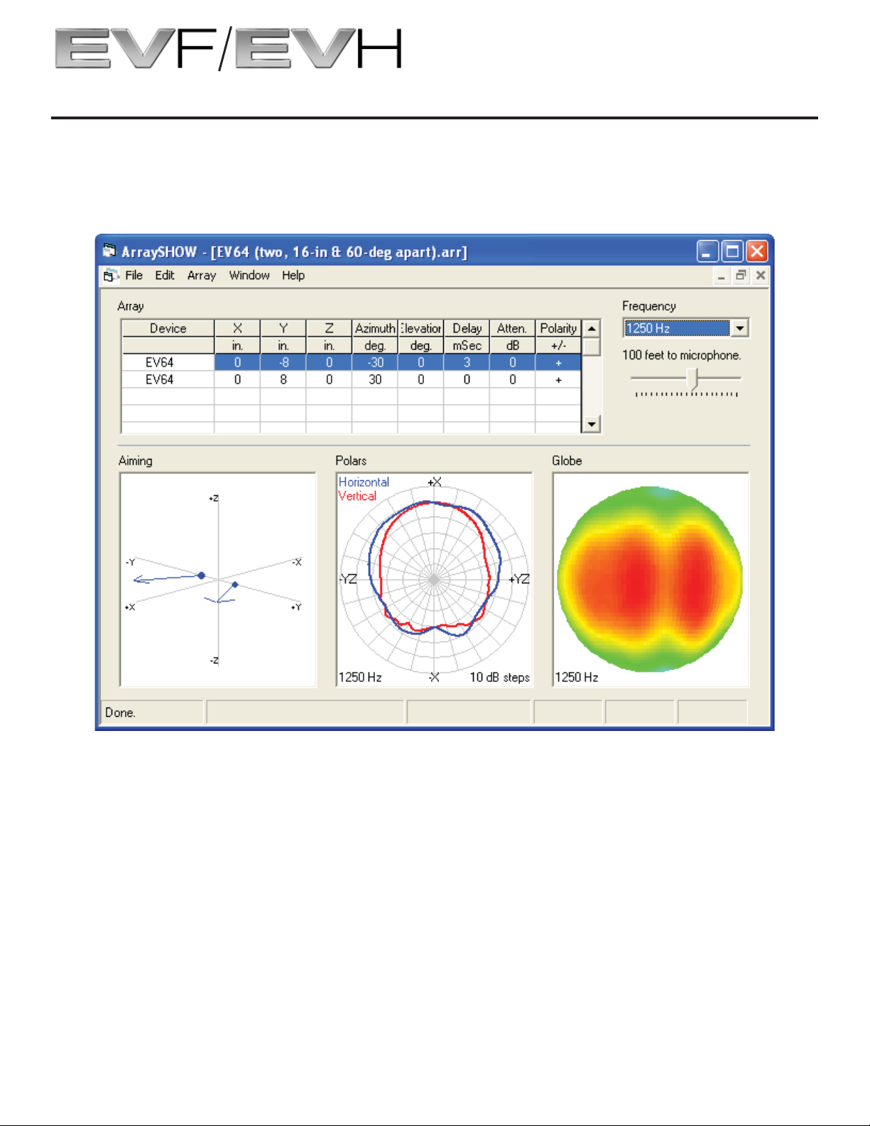
Finally, another way to reduce interference is to apply signal delay of up to 8 milliseconds to one of the
two systems. This requires a separate DSP (digital signal processor) drive to the delayed system. Figure
10 shows the dramatic smoothing achieved at 1,250 Hz. Note that the systems are still close together as
in Figure 6.
Figure 10:
Horizontal polar response (blue center plot) of two closely clustered 60° x 40° loudspeakers aimed 60°
apart, showing the smoothing of multiple-source interference caused by a 3-ms delay to one loudspeaker
In clusters with more than two systems, adjacent boxes are usually delayed. While the effect can be
predicted with appropriate software (such as EASE 4.2), the actual delays are typically established in the
fi eld during system setup and commissioning, by ear and measurements.
Electro-Voice EVF/EVH User Manual18
Page 19

4.0 Preparing EVF and EVH Systems for Installation
4.1 Recommended Prefl ight Procedures
For any installed sound system, certain checks made at the installer’s place of business can prevent
expensive on-site delays. A short-list follows, and sets the stage for proper cluster performance:
1. Unpack all loudspeakers in the shop.
2. Check for proper model numbers.
3. Check the overall condition of the loudspeakers.
4. Check for continuity at the loudspeaker inputs.
It is a good idea, once on site and the loudspeakers are connected, to check again for continuity at the
power-amplifi er end.
4.2 Passive/Biamp Crossover Confi guration
All two-way EVF and EVH systems are shipped in the passive crossover mode. In the center of the input
panel is an external switch card that can change this confi guration. See Figure 11. (Note that EVH input
panels, when the systems are in their normal, slanted-sides-vertical orientation, have their long axes
rotated 90° with respect to the EVF view of Figure 11.)
Figure 11:
EVF/EVH input panel as supplied, with the passive/biamp
switch card in its full-range passive position
(left position in picture as oriented)
Electro-Voice EVF/EVH User Manual 19
Page 20

4.0 Preparing EVF and EVH Systems for Installation (cont.)
To confi gure for biamp operation, remove the switch card by drawing it toward you using the central fi nger
hole. (The switch can also be removed with the end of a fl at-blade screwdriver, by placing the blade end
in the switch hole and using the adjacent edge of the input panel as a fulcrum. To facilitate this operation,
there is a small recess in the edge of the input panel adjacent to the hole in switch card.) Reinsert the
switch card in its biamp-operation position (right position in the picture of Figure 11).
4.3 Rotation of High-Frequency Waveguides (EVF systems)
All high-frequency waveguides have their horizontal and vertical patterns molded in for easy identifi cation
of orientation and are rotatable according to the following procedure:
1. With a #2 Phillips screwdriver, remove the four screws on each side of the enclosure and
pop the grille out.
2. With a #2 Phillips screwdriver, remove the 12 screws holding the compression-driver/
waveguide assembly.
3. Rotate the assembly 90° and reinstall.
4. Reinstall the grille.
4.4 Rotation of High-Frequency Waveguides and Mid-Frequency Waveguide Contours (EVH
systems)
1. With a #2 Phillips screwdriver, remove the four screws on each side of the enclosure and
pop the grille out.
2. With a #2 Phillips screwdriver, remove the four screws holding the compression-driver/HF
waveguide assembly.
3. Use a 6-mm Allen (hex) wrench to remove the two rails that hold the HF waveguide
assembly.
4. Use a 4-mm Allen (hex) wrench to remove the four screws holding the hard foam
mid-frequency waveguide contours in place on the left and right sides of the enclosure.
Figure 12 shows a contour in the process of being removed.
5. Rotate and reinstall the contours in the top and bottom of the enclosure.
6. Reinstall the two rails that hold the HF waveguide assembly.
7. Rotate and reinstall the compression-driver/HF waveguide assembly.
8. Reinstall the grille.
Electro-Voice EVF/EVH User Manual20
Page 21

4.0 Preparing EVF and EVH Systems for Installation (cont.)
Figure 12:
An EVH hard foam waveguide contour
being removed for reorientation
4.5 Digital Signal Processing
4.51 Full-Range Systems in Passive Mode
For full-range systems in the passive mode, the internal crossover/equalizer network sends low
frequencies to the woofer and high frequencies to the compression-driver/waveguide combination. In
addition, the network tailors the frequency response and levels of each individual driver so that the overall
frequency response of the loudspeaker is essentially fl at over its design operating range.
Once a cluster of EVF and/or EVH systems is installed in a venue, a digital signal processor (DSP) will
typically be used to adjust the in-room frequency response, based on the specifi cs of the situation. In
addition, the DSP should be used to provide the high-pass fi lters recommended to protect EVF and EVH
systems against overdrive at frequencies below their operating range. Failure to do so could damage the
low-frequency drivers if fed high-level signals below the system’s operating range. Table 3 shows the
recommend high-pass fi lter frequencies for infrasonic protection of EVF and EVH systems. Different
high-pass fi lter frequencies are recommended for some fi berglass versions based on changes in operation
range due to the effects of having a sealed enclosure.
Model(s) Recommended High-Pass Frequency (minimum)
EVF-1122/XX 65 Hz
EVF-1152/XX 45 Hz (55 Hz for Fiberglass Versions)
EVF-1121S 50 Hz (55 Hz for Fiberglass Versions)
EVF-1151S 35 Hz (45 Hz for Fiberglass Versions)
EVF-1181S 33 Hz
EVF-2121S 45 Hz
EVF-2151D 35 Hz
EVH-1152/XX 60 Hz
Table 3:
Recommended high-pass frequencies for infrasonic protection of EVF and EVH systems
Electro-Voice EVF/EVH User Manual 21
Page 22

4.0 Preparing EVF and EVH Systems for Installation (cont.)
4.52 Using the EVF-1121S and EVF-1151S Low-Frequency Systems in Full-Range Clusters that
Operate on a Single Power-Amplifi er Channel
The EVF-1121S and EVF-1151S low-frequency systems have integral passive low-pass fi lters that roll off
frequencies above 100 Hz at the rate of 12 dB per octave. This means that these systems can be used
to augment the low-frequency output of the EVF-1122/XX and EVF-1152/XX full-range systems without
the use of an external digital signal processor (DSP) for crossover from the low-frequency to the full-range
systems. As many as two full-range systems can be paralleled with an EVF low-frequency system on a
single power-amplifi er channel capable of driving a 2.1-ohm minimum impedance.
This simplifi ed, cost-effective confi guration is most appropriate for applications that require only moderate
or moderately high acoustic output. This is because the full-range systems cannot have the full infrasonic
protection provided by the high-pass fi lters specifi ed in Table 3. However, useful overall cluster protection
will be provided by employing the high-pass frequency recommended for the particular EVF low-frequency system used.
Note that the EVF-1181S, EVF-2121S, and EVF-2151D do not incorporate a low-pass fi lter.
4.53 DSP (Digital Signal Processor) Loudspeaker Presets for Biamp Operation
In the biamp mode, the crossover and equalization must be achieved external to the loudspeaker. This
is typically done with a digital signal processor (DSP) that has crossover and equalization fi lters that are
adjusted by the manufacturer to provide the essentially fl at frequency response mentioned above. The factory presets for the EVF and EVH loudspeakers have been determined for Electro-Voice processors and
are available for download at www.electrovoice.com. Presets for other popular processors often can be
provided by the Bosch Communications Systems/Electro-Voice technical support group; specifi c contact
information can be found at www.electrovoice.com.
By providing a single loudspeaker system with uniform frequency response, the loudspeaker presets are a
good starting point for equalizing a cluster of systems during setup and commissioning. Final equalization
of a cluster should be accomplished with additional equalization made in front of the DSP device, not by
modifying the preset crossover and equalization parameters in the low- and high-frequency outputs of the
DSP. The later is likely to produce undesirable frequency-response and directivity changes in the crossover region.
Electro-Voice EVF/EVH User Manual22
Page 23

5.0 EVF and EVH Rigging System
5.1 Introduction
5.11 The Flying EV-Innovation (EV-I) Loudspeaker System
All EVH and EVF loudspeaker systems incorporate heavy-duty M10-1.5 threaded attachment points on
each enclosure. These attachment points work in conjunction with (1) the M10 eyebolts included with
each loudspeaker or (2) the optional VRK and HRK rigging kits. The rigging kits allow the user to rig
multiple systems together in horizontal and vertical confi gurations. The horizontal and vertical rigging kits
are an open-ended design, meaning that any system in the EVF and EVH families can rig to any other.
The vertical and horizontal rigging plates give the user ultimate fl exibility for splay angles from 0° to 45°
degrees in 5° increments (0° to 20° for EVF to EVF subwoofer). This system was designed to allow the
end user to construct a loudspeaker cluster to fi t nearly any application. Figure 13 and Table 4 show the
possible connections using the three VRK and HRK rigging kits to connect any EVF or EVH loudspeaker.
Model Orientation Color Function
VRK-1B/
VRK-1W
HRK-1B/
HRK-1W
Vertical
Cluster
Horizontal
Cluster
Black/
White
Black/
White
EVF full-range and
low-frequency systems
EVF full-range and
low-frequency systems
Figure 13a:
VRK-1 or HRK-1 connection
Figure 13b:
VRK-2 or HRK-2 connection
Table 4a:
VRK-1 or HRK-1 connection
Model Orientation Color Function
EVF full-range or
VRK-2B/
VRK-2W
HRK-2B/
HRK-2W
Plates may need to be fl ipped depending on which side is
being connected, due to asymmetry of the plates.
Vertical
Cluster
Horizontal
Cluster
Black/
White
Black/
White
low-frequency systems
to EVF subwoofer or
EVH full-range
EVF full-range or
low-frequency systems
to EVF subwoofer or
EVH full-range
Table 4b:
VRK-2 or HRK-2 connection
Model Orientation Color Function
VRK-3B/
VRK-3W
HRK-3B/
HRK-3W
Vertical
Cluster
Horizontal
Cluster
Black/
White
Black/
White
EVF subwoofer and
EVH full-range
EVF subwoofer and
EVH full-range
Figure 13c:
VRK-3 or HRK-3 connection
Electro-Voice EVF/EVH User Manual 23
VRK-3 or HRK-3 connection
Table 4c:
Page 24

5.0 EVF and EVH Rigging System (cont.)
M5 Split Lock
Washer (x8)
EVF Long Rigging
Plate (x2)
EVF Stabilizing
Bar (x2)
EVF-SUB Long
Rigging Plate (x2)
EVF Stabilizing
Bar (x2)
4.87 lb
(2.21 kg)
0.88 lb
(0.40 kg)
M10 Split Lock
Washer (x8)
Figure 14a:
VRK-1 rigging kit with parts identifi ed
M5 Split Lock
Washer (x8)
5.44 lb
(2.47 kg)
0.88 lb
(0.40 kg)
M10 Split Lock
Washer (x8)
EVF Short Rigging
Plate (x2)
M5 Screw
(x8)
EVF-SUB Short
Rigging Plate (x2)
M5 Screw
(x8)
3.11 lb
(1.41 kg)
M10 Screw
(x8)
3.25 lb
(1.48 kg)
M10 Screw
(x8)
M10 Split Lock
Washer (x8)
M5 Split Lock
Washer (x8)
VRK-2 rigging kit with parts identifi ed
EVH Long Rigging
Plate (x2)
EVH Stabilizing
Bar (x2)
VRK-3 rigging kit with parts identifi ed
Figure 14b:
6.67 lb
(3.03 kg)
1.52 lb
(0.69 kg)
Figure 14c:
M5 Screw
Electro-Voice EVF/EVH User Manual24
EVH Short Rigging
Plate (x2)
(x8)
3.04 lb
(1.38 kg)
M10 Screw
(x8)
Page 25

5.0 EVF and EVH Rigging System (cont.)
EVF Long Rigging
Plate (x2)
EVF-SUB Long
Rigging Plate (x2)
7.33 lb
(3.33 kg)
7.90 lb
(3.59 kg)
M10 Split Lock
Washer (x8)
M10 Screw
(x8)
Figure 15a:
HRK-1 rigging kit with parts identifi ed
M10 Split Lock
Washer (x8)
M10 Screw
(x8)
Figure 15b:
HRK-2 rigging kit with parts identifi ed
EVF Short Rigging
Plate (x2)
EVF-SUB Short
Rigging Plate (x2)
5.57 lb
(2.53 kg)
5.71 lb
(2.59 kg)
EVH Long Rigging
Plate (x2)
9.13 lb
(4.15 kg)
M10 Split Lock
Washer (x8)
M10 Screw
(x8)
EVH Short Rigging
Plate (x2)
5.50 lb
(2.50 kg)
Figure 15c:
HRK-3 rigging kit with parts identifi ed
Electro-Voice EVF/EVH User Manual 25
Page 26

5.0 EVF and EVH Rigging System (cont.)
5.12 Important Details that Apply to the VRK and HRK Rigging Kits
Both the VRK and HRK kits include all necessary mounting hardware (as shown in Figures 14 and 15).
Additionally, the VRK kits include a set of low-profi le stabilizer bars to both simplify alignment of the enclosures during the rigging process and keep the front edges of the systems neatly aligned. Additional hardware is included in the VRK kits to mount these stabilizer bars. The stabilizer bars mount to the insides of
the vertical rigging plates for a clean appearance. Stabilizer bars can be seen in Figure 14 and, installed,
in Figure 21.
The HRK horizontal rigging kits have a tie plate that is welded to the center of the rigging plate. This tie
plate is for suspending the top systems in a cluster and for suspending lower systems below (with usersupplied hardware). It has six holes that fi t a standard 5/8-inch shackle (user supplied). Tie plates can be
seen in Figure 15 and, installed, in Figure 22.
Both the VRK and the HRK rigging plates use arrow designators and a series of letters by each of the
mounting holes to ensure that the desired angle is achieved. Refer to Tables 5, 6, and 7 for a description
of the appropriate arrow direction and letter.
All rigging plates except the EVF-to-EVF-subwoofer rigging plates are symmetrical, meaning that the
mounting-hole layouts are the same from the left to the right sides of the rigging plate. The EVF-to-EVFsubwoofer rigging plates are asymmetrical, meaning that one side is for subwoofers, labeled “Sub,” and
the other side is for EVF’s, labeled “EVF.” This rigging plate must be fl ipped over depending on which side
the subwoofer is on. This asymmetry is shown in Figure 15b.
All user-supplied hardware must be overhead load-rated (using applicable safety factors) for the specifi c
cluster. See section 6.0 for additional details on load limits and safety factors.
5.2 EV-I Rigging Primer
The following sections describe the clustering of EVF and EVH systems using one of the following three
approaches:
1. EVI-M10K eyebolt kits supplied with each system (used in conjunction with other user-supplied hardware).
2. Optional VRK vertical rigging kits, in conjunction with the supplied eyebolt kits and usersupplied hardware.
3. Optional HRK horizontal rigging kits, in conjunction with the supplied eyebolt kits and usersupplied hardware.
In all cases, note that the weight of the cluster can be substantial and the building structure must be capable of supporting the weight. (System weights are given in Figure 1.)
The optional VRK and HRK rigging kits are the most convenient way to assemble EVF and EVH clusters,
offering a great deal of fl exibility in box aiming angles. Using the supplied eyebolt kits with additional usersupplied hardware is more diffi cult, but does allow the most fl exibility, since not only can box aiming angles
be determined but also the boxes can be rotated about their aiming axes, which can improve coverage
uniformity in certain venue shapes (EASE 4.2 allows this option).
Electro-Voice EVF/EVH User Manual26
Page 27
5.0 EVF and EVH Rigging System (cont.)
5.21 Anatomy of an EVF or EVH Flying System Using M10 Eyebolts
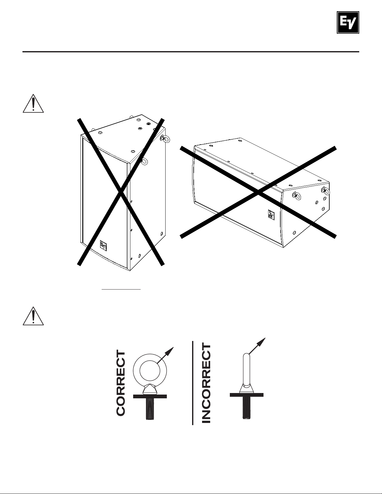
5.211 Eyebolt Application Warnings
NO EYEBOLT SHOULD BE MOUNTED IN THE SIDES OF ANY EVF OR EVH ENCLOSURE
IN ORDER TO SUSPEND A SYSTEM OR CLUSTER FROM THE TOP.
Figure 16:
Eyebolts installed incorrectly in the sides of an enclosure in order to suspend it from above
EYEBOLTS MUST BE FULLY SEATED AND ORIENTED IN THE PLANE OF PULL AS
SHOWN IN FIGURE 17. ALWAYS USE WASHERS TO DISTRIBUTE SUSPENSION LOADS.
REFER TO SECTION 6.3 FOR SPECIFIC EYEBOLT WEIGHT AND ANGLE RESTRICTIONS.
Figure 17:
Illustration showing the use of washers with fully seated eyebolts,
with correct orientation in the plane of pull
Electro-Voice EVF/EVH User Manual 27
Page 28

5.0 EVF and EVH Rigging System (cont.)
5.212 Eyebolt Installation
Installation instructions follow:
1. Remove the M10 fl at-head bolts from the enclosure (see Figure 18a).
2. Screw the lifting eyebolt with fender washer into the threaded attachment point until the
fender washer has contacted the enclosure (see Figure 18b).
3. Continue to fi nger tighten the eyebolt until the correct alignment position is obtained, a
maximum of one complete turn.
4. All hardware supplied by the user must be rated for overhead lifting to suspend the
loudspeaker system.
5. Never install the eyebolt without the factory-supplied washer.
Eyebolts must be fully seated and oriented in the plane of pull (see section 5.211 Eyebolt Application
Warnings, Figure 17). Always use the factory-supplied fender washer to distribute the load on the enclosure. Over tightening the eyebolt with a wrench, screwdriver, etc., can result in a system failure and possible injury.
Figure 18a:
Removal of the fl at-head bolts
from the enclosure
Figure 18b:
Installation of eyebolts and washers
to the enclosure
Electro-Voice EVF/EVH User Manual28
Page 29

5.0 EVF and EVH Rigging System (cont.)
5.213 All-Eyebolt Clusters
A basic two-cabinet fl ying system is shown in Figures 19 and 20, illustrating the components necessary
to make a typical two-system horizontal or vertical cluster using M10 eyebolts. Secure cabinets to the
building structure with user-supplied hardware. All user-supplied hardware, shackles, wire rope, bolt
connectors, etc., must be rated for overhead lifting. Refer to section 1 for suspension point locations.
A second enclosure may be suspended from the fi rst by using the same M10 rigging points on the second
enclosure. Connection between the two enclosures through the M10 eyebolts requires hardware supplied
by the end user. All user-supplied hardware must be rated for overhead lifting. The angle between the
two enclosures as well as the angle between the fi rst enclosure and the structure can be controlled by
the length of the user-supplied hardware. If the desired angle cannot be achieved by varying the length of
this hardware, then pull-back points can be used. It is recommended that both the top and the second box
use a pull back. The pull back can be achieved with the use of additional M10 eyebolts at the back of the
enclosures. The hardware used to achieve the pull back is supplied by the end user.
A MAXIMUM OF TWO ENCLOSURES IS ALLOWED WITH ALLEYEBOLT CLUSTERS.
A MINIMUM OF TWO EYEBOLTS ARE REQUIRED FOR SUSPENSION OF ALLEYEBOLT
CLUSTERS.
U-Bracket
Point Only,
Not for
Eyebolt
Suspension!
Figure 19a:
A two-system vertical cluster
using the eyebolt kit supplied with
each system plus user-supplied
hardware (not shown), using a
A two-system vertical cluster
using the eyebolt kit supplied with
each system plus user-supplied
hardware (not shown), using a
moderate trim angle
Electro-Voice EVF/EVH User Manual 29
Figure 19b:
more extreme trim angle
Figure 19c:
A two-system vertical cluster
using the eyebolt kit supplied with
each system plus user-supplied
hardware (not shown), using an
extreme trim angle
Page 30

5.0 EVF and EVH Rigging System (cont.)
A horizontal two-cabinet eyebolt hang, shown in Figure 20, is similar to a vertical hang (shown in Figure
19), but with the cabinets rotated and other surfaces used for mounting eyebolts.
Figure 20a:
A two-system horizontal cluster using the
eyebolt kit supplied with each system plus
user-supplied hardware (not shown), using
a moderate trim angle
Figure 20c:
A two-system horizontal cluster using the
eyebolt kit supplied with each system plus
user-supplied hardware (not shown), using
an extreme trim angle
Figure 20b:
A two-system horizontal cluster using the
eyebolt kit supplied with each system plus
user-supplied hardware (not shown), using
a more extreme trim angle
Electro-Voice EVF/EVH User Manual30
Page 31

5.0 EVF and EVH Rigging System (cont.)
5.22 VRK Kits and Vertically Rigged Clusters
A basic three-enclosure vertical hang is shown in Figure 21. The following components are necessary to
construct this cluster:
1. One VRK-1 vertical rigging kit for EVF to EVF.
2. One VRK-2 vertical rigging kit for EVF to EVF subwoofer.
3. Four M10 eyebolts from the supplied EVI-M10K eyebolt kit (to suspend the top cabinet).
EVI-M10K Kit
VRK-2 Kit
(Sold Separately)
VRK-1 Kit
(Sold Separately)
Figure 21a:
Basic three-enclosure vertical hang of
an EVF subwoofer on top and two EVF
full-range systems below, using one
each VRK-1 and VRK-2 kits (optional
accessories) and four eyebolts (supplied
with systems), using a moderate trim
angle
EVF Subwoofer
EVF Full-Range
System
Stabilizer Bars
Figure 21b:
Basic three-enclosure vertical hang of
an EVF subwoofer on top and two EVF
full-range systems below, using one
each VRK-1 and VRK-2 kits (optional
accessories) and four eyebolts (supplied
with systems), using a more extreme trim
angle
Figure 21c:
Basic three-enclosure vertical hang of
an EVF subwoofer on top and two EVF
full-range systems below, using one
each VRK-1 and VRK-2 kits (optional
accessories) and four eyebolts (supplied
with systems), using an extreme trim
angle
Electro-Voice EVF/EVH User Manual 31
Page 32
5.0 EVF and EVH Rigging System (cont.)
5.23 HRK Kits and Horizontally Rigged Clusters
The main difference between the HRK and the VRK rigging kits is the addition of a tie plate in the center
of the rigging plate. Tie plates are identifi ed in Figure 22.
MAIN SUSPENSION LINES AND PULL BACKS MUST BE TIED TO THE TIE PLATES.
Enclosures may be suspended below using the HRK rigging kits. Connection between the enclosures
through the tie plates within the HRK kits requires hardware supplied by the end user. All user-supplied
hardware must be rated for overhead lifting. The angle between the two enclosures as well as the angle
between the fi rst enclosure and the structure can be controlled by the length of the user-supplied hardware. If the desired angle cannot be achieved by varying the length of this hardware, then pull-back points
can be used. It is recommended that both the top and the second box use a pull back. A pull back can be
achieved through the use of attachment to the tie plates. Stabilization can be achieved through the use of
M10 eyebolts at the back of the enclosures. The hardware used to achieve the pull back is supplied by the
end user.
A basic two-over-two cluster is shown in Figure 22.
NOTE THAT THE HRK KITS ARE DESIGNED TO MAKE WEIGHTSYMMETRICAL CLUS
TERS, I.E., THOSE WHOSE LEFTTORIGHT CENTER OF GRAVITY IS IN THE CENTER OF
THE CLUSTER.
The following components are needed to achieve this cluster:
1. Two HRK-1 horizontal rigging kits for EVF to EVF.
2. User-supplied hardware to link the upper cluster to the lower cluster.
Electro-Voice EVF/EVH User Manual32
Page 33

5.0 EVF and EVH Rigging System (cont.)
HRK-1 Kit (x2)
Tie Plates
(Sold Separately)
Rigging Plates
(Within the
HRK Kits)
Tie Plates
(As Shipped,
Attached to the
Rigging Plates
Within the
HRK Kits)
EVF Full-Range
Systems (x4)
Figure 22a:
A four-enclosure horizontal hang
of two EVF full-range systems
above and two EVF full-range
systems below, connected by two
HRK-1 kits (optional accessories)
and user-supplied hardware to
link both clusters, using a
moderate trim angle
A four-enclosure horizontal hang
of two EVF full-range systems
above and two EVF full-range
systems below, connected by two
HRK-1 kits (optional accessories)
and user-supplied hardware to
link both clusters, using a
Figure 22b:
more extreme trim angle
A basic three-over-three cluster is shown in Figure 23.
MAIN SUSPENSION LINES AND PULL BACKS MUST BE TIED TO THE TIE PLATES.
NOTE THAT THE HRK KITS ARE DESIGNED TO MAKE WEIGHTSYMMETRICAL
CLUSTERS, I.E., THOSE WHOSE LEFTTORIGHT CENTER OF GRAVITY IS IN THE
CENTER OF THE CLUSTER.
Optional Stabilization
Points
Figure 22c:
A four-enclosure horizontal hang
of two EVF full-range systems
above and two EVF full-range
systems below, connected by two
HRK-1 kits (optional accessories)
and user-supplied hardware to
link both clusters, using an
extreme trim angle
The following components are needed to achieve this cluster:
1. Four HRK-2 horizontal rigging kits for EVF to EVF subwoofer/EVH.
2. User-supplied hardware to link the upper cluster to the lower cluster.
Electro-Voice EVF/EVH User Manual 33
Page 34

5.0 EVF and EVH Rigging System (cont.)
Figure 23a:
A six-enclosure horizontal hang
of three systems above and three
systems below, connected by four
HRK-2 kits (optional accessories)
and user-supplied hardware to
link both clusters, using a
moderate trim angle
Figure 23c:
A six-enclosure horizontal hang of three systems above
and three systems below, connected by four HRK-2 kits
(optional accessories) and user-supplied hardware to
link both clusters, using an extreme trim angle
A six-enclosure horizontal hang of three systems above and
three systems below, connected by four HRK-2 kits
(optional accessories) and user-supplied hardware to
link both clusters, using a more extreme trim angle
Figure 23b:
Electro-Voice EVF/EVH User Manual34
Page 35

5.0 EVF and EVH Rigging System (cont.)
5.24 Assembly Instructions for VRK and HRK kits
Both the VRK and HRK rigging kits share the same mounting hole positions and letter designations.
Tables 5, 6, and 7 apply to both the VRK and HRK kits. The only difference between the kits is the HRK
rigging plates have an integral tie plate and the VRK kits use a stabilizing bar.
1. Refer to Tables 5, 6, or 7 to determine which lettered hole position to use. Follow the
directions in these tables for arrow direction and positioning on the cabinet. Note that
“Front” will always refer to the front of the enclosure (i.e., the grille).
2. HRK kits skip to step 3. For VRK kits, preassemble them using the supplied hardware by
attaching the stabilizer bar to both the large and small rigging plates. Attach the stabilizer
bars to the back side of the plates, using a #2 Phillips screwdriver, the eight M5 pan-head
machine screws and M5 split-lock washers supplied with the hardware kit. You are now
ready to attach the VRK kits to the loudspeakers.
3. Referring to Tables 5, 6 or 7 (depending on which systems are being connected), fi nd which
rigging-plate letter will give you the desired angle. Also pay attention to the arrow direction
as listed in the table.
4. With a 6-mm Allen (hex) wrench, remove the M10 fl athead bolts that were installed by the
factory. Remove only those bolts that are going to be replaced by rigging hardware, in order
to remain safe and avoid audible enclosure leaks.
5. Using the appropriately lettered rigging-plate holes, attach the VRK or HRK kits to the
enclosure sides using the eight supplied M10 button-head bolts and split-lock washers.
Use a 6-mm Allen (hex) wrench.
6. Install any M10 eyebolts that are needed for suspension, pull back, or stabilization at this
time.
7. Ensure that all M10 bolt points in the enclosure have an M10 fl athead bolt, an M10 eyebolt
or an M10 button-head bolt where the rigging plates attach. Do not hang any cluster with
missing M10 bolts!
8. Check all M10 and M5 fasteners and eyebolts to ensure they are tight.
9. You are now ready to hoist the cluster and make the fi nal attachments to the building
structure.
Electro-Voice EVF/EVH User Manual 35
Page 36

5.0 EVF and EVH Rigging System (cont.)
Table 5:
For clustering EVF full-range and
low-frequency (not subwoofer)
systems using VRK-1 or
HRK-1 rigging kits
Table 6:
For clustering EVF full-range
and low-frequency systems to
EVF subwoofers and EVH using
VRK-2 or HRK-2 rigging kits
Letter
Rigging-Plate
Position
Arrow Direction
(both rigging plates)
A Short in front Toward grille 0°
B Short in front Toward grille 5°
C Short in front Toward grille 10°
D Short in front Toward grille 15°
E Long in front Toward input panel 20°
F Long in front Toward input panel 25°
G Long in front Toward input panel 30°
H Long in front Toward input panel 35°
I Long in front Toward input panel 40°
D Long in front Toward input panel 45°
Letter
Rigging-Plate
Position
Arrow Direction
(both rigging plates)
A Short in front Toward grille 0°
B Short in front Toward grille 5°
C Short in front Toward grille 10°
D Short in front Toward grille 15°
E Short in front Toward grille 20°
Angle
Angle
Hole-to-Hole Dim.
(Short Bar/Long Bar)
6.276” [159.41mm]
11.518” [292.56mm]
5.958” [151.33mm]
10.338” [262.59mm]
5.630” [143.00mm]
9.144” [232.26mm]
5.292” [134.42mm]
7.934” [201.52mm]
6.710” [170.43mm]
4.946” [125.63mm]
5.476” [139.09mm]
4.592” [116.64mm]
4.230” [107.44mm]
4.228” [107.39mm]
4.592” [116.64mm]
5.472” [138.99mm]
4.946” [125.63mm]
6.708” [170.38mm]
5.292” [134.42mm]
7.934” [201.52mm]
Hole-to-Hole Dim.
(Short Bar/Long Bar)
5.913” [150.19mm]
10.258” [260.55mm]
5.595” [142.11mm]
9.080” [230.63mm]
5.268” [133.81mm]
7.889” [200.38mm]
4.932” [125.27mm]
6.685” [169.80mm]
4.588” [116.54mm]
5.468” [138.89mm]
Table 7:
For clustering EVF subwoofers
and EVH systems using VRK-3
or HRK-3 rigging kits
Letter
Rigging-Plate
Position
Arrow Direction
(both rigging plates)
Angle
Hole-to-Hole Dim.
(Short Bar/Long Bar)
A Short in front Toward grille N/A Not Used
B Short in front Toward grille 0°
C Short in front Toward grille 5°
D Short in front Toward grille 10°
E Short in front Toward grille 15°
F Short in front Toward grille 20°
A Long in front Toward input panel 45°
B Long in front Toward input panel 40°
C Long in front Toward input panel 35°
D Long in front Toward input panel 30°
E Long in front Toward input panel 25°
F Long in front Toward input panel 20°
5.554” [141.07mm]
12.466” [316.64mm]
5.234” [107.44mm]
10.430” [264.92mm]
4.908” [124.66mm]
8.376” [212.75mm]
4.572” [116.13mm]
6.308” [160.22mm]
4.230” [107.44mm]
4.230” [107.44mm]
5.892” [149.66mm]
14.506” [368.45mm]
5.554” [141.07mm]
12.466” [316.64mm]
5.234” [107.44mm]
10.430” [264.92mm]
4.908” [124.66mm]
8.376” [212.75mm]
4.572” [116.13mm]
6.308” [160.22mm]
4.230” [107.44mm]
4.230” [107.44mm]
Electro-Voice EVF/EVH User Manual36
Page 37

6.0 Rigging-Strength Ratings and Safety Factors
6.1 Working Load Limit and Safety-Factor Defi nitions
The structural ratings for all of the EVF and EVH rigging components and complete loudspeaker systems
are based on test results in which parts were stressed to failure. Manufacturers typically present the
structural-strength ratings of mechanical components or systems as either the Working Load Limit (WLL)
or the ultimate-break strength. Electro-Voice chooses to present the structural-load ratings of the EVF and
EVH loudspeaker systems as the WLL. The WLL rating represents the maximum load that should ever be
applied to a mechanical component or system.
THE USER SHOULD NEVER APPLY A LOAD THAT EXCEEDS THE WLL OF ANY OF THE
RIGGING COMPONENTS OR COMPLETE LOUDSPEAKER SYSTEMS DESCRIBED IN
THIS MANUAL.
The WLL for the EVF and EVH rigging components and complete loudspeaker systems described in this
manual are based on a minimum 8:1 safety factor. The safety factor is defi ned as the ratio of the
ultimate-break strength divided by the WLL, where the ultimate-break strength represents the force
at which a part will structurally fail. For example, if a part has a WLL of 1,000 lb (454 kg), it would not
structurally fail until a force of at least 8,000 lb (3,629 kg) was applied, based on an 8:1 safety factor.
However, the user should never apply a load to that part that exceeds 1,000 lb (454 kg). The safety factor
provides a margin of safety above the WLL to accommodate normal dynamic loading and normal wear.
CAUTIONS for Working Load Limits and Safety Factors
The WLL defi ned by the manufacturer of any rigging component should never be exceeded. Electro-Voice
bases the WLL of its EVF and EVH products on a minimum of an 8:1 safety factor. Other manufacturers of
rigging components may base their WLL on safety factors other than 8:1. For example, 5:1 safety factors
are fairly common among rigging manufacturers because many regulatory agencies call for a minimum
safety factor of 5:1.
When an EVF and EVH loudspeaker system is installed where local regulations only require a safety factor
of 5:1, Electro-Voice insists that the WLL of the EVF and EVH rigging never be exceeded and that an 8:1
safety factor be maintained for the EVF and EVH loudspeakers.
The user is cautioned that some local regulations may require safety factors higher than 8:1. In that
circumstance, Electro-Voice insists that the user maintain the higher safety factor as required by the local
regulations throughout the entire EVF and EVH installation. It is the responsibility of the user to make sure
that any EVF and EVH installation meets all applicable local, state or federal safety regulations.
Electro-Voice EVF/EVH User Manual 37
Page 38

6.0 Rigging-Strength Ratings and Safety Factors (cont.)
6.2 Structural Rating Overview
Designing a safe structural cluster is usually a very complex process best left to experienced professionals. Since the EVH and EVF rigging options allow the user to confi gure a wide variety of clusters, the
following guidelines have been broken into three sections: eyebolts, vertical rigging and horizontal rigging.
Each section will give the end user guidelines for maximum weight and height of clusters. At the end of
each section, typical clusters will be recommended. The following is a short synopsis of the considerations involved.
There are three independent strength ratings that, together with listed maximums, give a complete description of the overall structural capabilities of the loudspeaker cluster.
1. The strength of each M10-1.5 threaded attachment point in each of the individual enclosures. This is the strength of the M10 corner bracket and the enclosure.
2. The strength of the rigging plates included in the VRK and HRK rigging kits described in
section 5.0 EVF and EVH Rigging System.
3. The strength of the M10-1.5 eyebolts.
Using the three strength ratings listed above, maximum cluster heights and weights will be recommended
so that the cluster maintains an 8:1 safety factor.
In any cluster, the forces acting on each loudspeaker (on each individual rigging point and on the enclosure) and the forces acting on each point of the rigging accessory (M10-1.5 eyebolts, rigging plates and
tie plates) will vary with each cluster confi guration. Determining those forces throughout a cluster requires
complex mathematical calculations. Electro-Voice engineers have therefore defi ned a set of simplifi ed
structural-rating guidelines for both vertical and horizontal clusters that eliminates the need for complex
calculations. The interaction of complex forces throughout EVF and EVH clusters was analyzed using a
combination of destructive testing and computer modeling to develop this set of conservative guidelines,
presented below, to enable a rigger to immediately determine on site whether or not a cluster is safe without having to make weight-distribution calculations.
Electro-Voice EVF/EVH User Manual38
Page 39

6.0 Rigging-Strength Ratings and Safety Factors (cont.)
6.3 All-Eyebolt Structural Ratings
The guidelines for simplifi ed all-eyebolt structural ratings cover the following information:
1. Maximum number of enclosures.
2. Maximum weight of the cluster.
3. WLL for eyebolts.
4. Suspension-line angles.
5. Left-to-right all-eyebolt cluster angles.
THE MAXIMUM LOAD, MAXIMUM NUMBER OF ENCLOSURES AND MINIMUM NUMBER
OF SUSPENSION LINES FOR ALLEYEBOLT CLUSTERS ARE LISTED IN TABLE 8.
LIMITS FOR ALL-EYEBOLT CLUSTERS ONLY
Maximum Working
Load Limit
291 lb (132 kg) Two, either vertical or horizontal Two (for any all-eyebolt cluster)
Maximum Number of
Enclosures
Minimum No. of Suspension Lines
Table 8:
Maximum load, maxiumum number of enclosures and minimum number of
suspension lines for all-eybolt clusters
Minimum of Two
Suspension Lines
Minimum of Two
Suspension Lines
Maximum of Two
Enclosures
Maximum of Two
Enclosures
Max. Cluster Weight
Max. Cluster Weight
286 lb (130 kg)
Figure 24a:
Limitations for vertical all-eyebolt clusters
Electro-Voice EVF/EVH User Manual 39
286 lb (130 kg)
Figure 25b:
Limitations for horizontal all-eyebolt clusters
Page 40

0
50
100
150
200
250
300
350
400
450
500
550
600
650
0 102030405060708090
Angle (Degrees)
Working Load Limit (lb)
0
23
45
68
91
113
136
159
181
204
227
249
272
295
Working Load Limit (kg)
575 lb (261 kg) @ 0°
262 lb (119 kg) @ 30°
185 lb (84 kg) @ 60°
171 lb (78 kg) @ 90°
6.0 Rigging-Strength Ratings and Safety Factors (cont.)
6.31 Working Load Limits for Eyebolts
Eyebolts can be used to suspend individual loudspeakers and certain types of clusters. Eyebolts attach
to the EVF and EVH enclosures through the integral M10-1.5 attachment points. Section 5.21 Anatomy
of an EVF or EVH Flying System Using M10 Eyebolts should be reviewed at this time for more information
on eyebolt alignment and positioning on the enclosure. Table 9 shows the WLL per eyebolt with respect
to the angle of the applied load. Figure 25 shows the suspension-point angles that are referenced in the
table. It is a good idea to stay within 30° of the maximum WLL of the eyebolt (straight up position) for
main suspension lines.
Table 9:
WLL for M10
eyebolts in the
EVI-M10K
eyebolt kit
Suspension line angle limits for
individual eyebolts, both in plane
of pull (left) and against plane
40
Figure 25:
of pull (right)
Electro-Voice EVF/EVH User Manual
Page 41

6.0 Rigging-Strength Ratings and Safety Factors (cont.)
6.32 Suspension-Line Angles
Refer to Table 9 and Figure 25 for specifi c eyebolt angle and weight limitiations when using all-eyebolt
clusters. These limits are not to be exceeded under any circumstances. If a higher safety factor than 8:1
is required, the angle limitations for each eyebolt may actually decrease to a number less than what is
shown in Figure 25.
Always make sure that the suspension line is in the plane
of the eyebolt, as shown in Figure 17. Readjust the eyebolt
during the installation if necessary to maintain this alignment.
Figure 26a:
All-eyebolt suspension-line angle limit,
independent suspension lines
6.33 Left-to-Right All-Eyebolt Cluster Angles
The suspended all-eyebolt cluster must be perpendicular (plumb) to within ±5° as shown in Figure 27.
All-eyebolt suspension-line angle limit,
Figure 26b:
bridled suspension lines
Figure 27:
Left-to-right angle limits for an all-eyebolt cluster (angle shown exaggerated for illustration purposes)
Electro-Voice EVF/EVH User Manual 41
Page 42

6.0 Rigging-Strength Ratings and Safety Factors (cont.)
6.4 VRK Rigging Structural Ratings for Vertical Clusters
The guidelines for simplifi ed vertical structural ratings cover the following information:
1. Maximum length of the cluster.
2. Maximum weight of the cluster.
3. WLL for eyebolts.
4. Trim angle.
5. Tie points for eyebolts.
6. Left-to-right vertical cluster angles.
The majority of vertical clusters will be suspended using a combination of VRK vertical rigging kits and
factory-supplied eyebolts. For a vertical cluster, select the eyebolt position that results in the highest eyebolt strength as shown in Table 12. Different eyebolt positions are shown in Figure 28.
Max. Cluster Weight
475 lb (216 kg)
Max. Cluster Weight
475 lb (216 kg)
Figure 28a:
Load-bearing suspension points used for
positive or moderate negative trim angles
Figure 28b:
Load-bearing suspension points used for
more extreme negative trim angles
Electro-Voice EVF/EVH User Manual42
Page 43
6.0 Rigging-Strength Ratings and Safety Factors (cont.)
THE MAXIMUM LOAD, MAXIMUM LENGTH AND EYEBOLT ANGLE RESTRICTIONS FOR
VERTICAL CLUSTERS ARE LISTED IN TABLE 10.
LIMITS FOR VERTICAL CLUSTERS ONLY
Maximum Working
Load Limit
482 lb (219 kg)
Maximum Length Eyebolt Angle Restrictions
7.5 ft (228.6 cm)
(as shown in Figure 27)
When using eyebolts, refer to Table 12 and
Figure 29 for angle restrictions.
Table 10:
Maximum load, maximum length and eyebolt angle restrictions for vertical clusters
Table 11 gives a brief guide to the cluster combinations possible within the WLL of the EVF and EVH
enclosures.
LIMITS FOR VERTICAL CLUSTERS ONLY
Clustered Enclosures
EVH-1152/XX full-range
and/or EVF subwoofer
EVF-1122/XX and/or
EVF 12” low-frequency
EVF-1152/XX and/or
EVF 15” low-frequency
One EVF subwoofer and
four EVF-1122/XX
Two EVF subwoofer and
two EVF-1122/XX
One EVF subwoofer and
three EVF-1152/XX
Two EVF subwoofer and
two EVF-1152/XX
Maximum Number
of Enclosures
3
5
4
5
4
4
4
Minimum No. of
Suspension Lines
4
(2 per side)
4
(2 per side)
4
(2 per side)
4
(2 per side)
4
(2 per side)
4
(2 per side)
4
(2 per side)
Eyebolt Angle
Restrictions
See Table 12
and Figure 29
See Table 12
and Figure 29
See Table 12
and Figure 29
See Table 12
and Figure 29
See Table 12
and Figure 29
See Table 12
and Figure 29
See Table 12
and Figure 29
Table 11:
Possible vertical cluster combinations within the WLL of each enclosure
For clusters with trim angles between +20° and –10°, or where a rear pull back will not be used, the four
eyebolt attachment points on the top surface of the vertical cluster should be used.
Electro-Voice EVF/EVH User Manual 43
Page 44
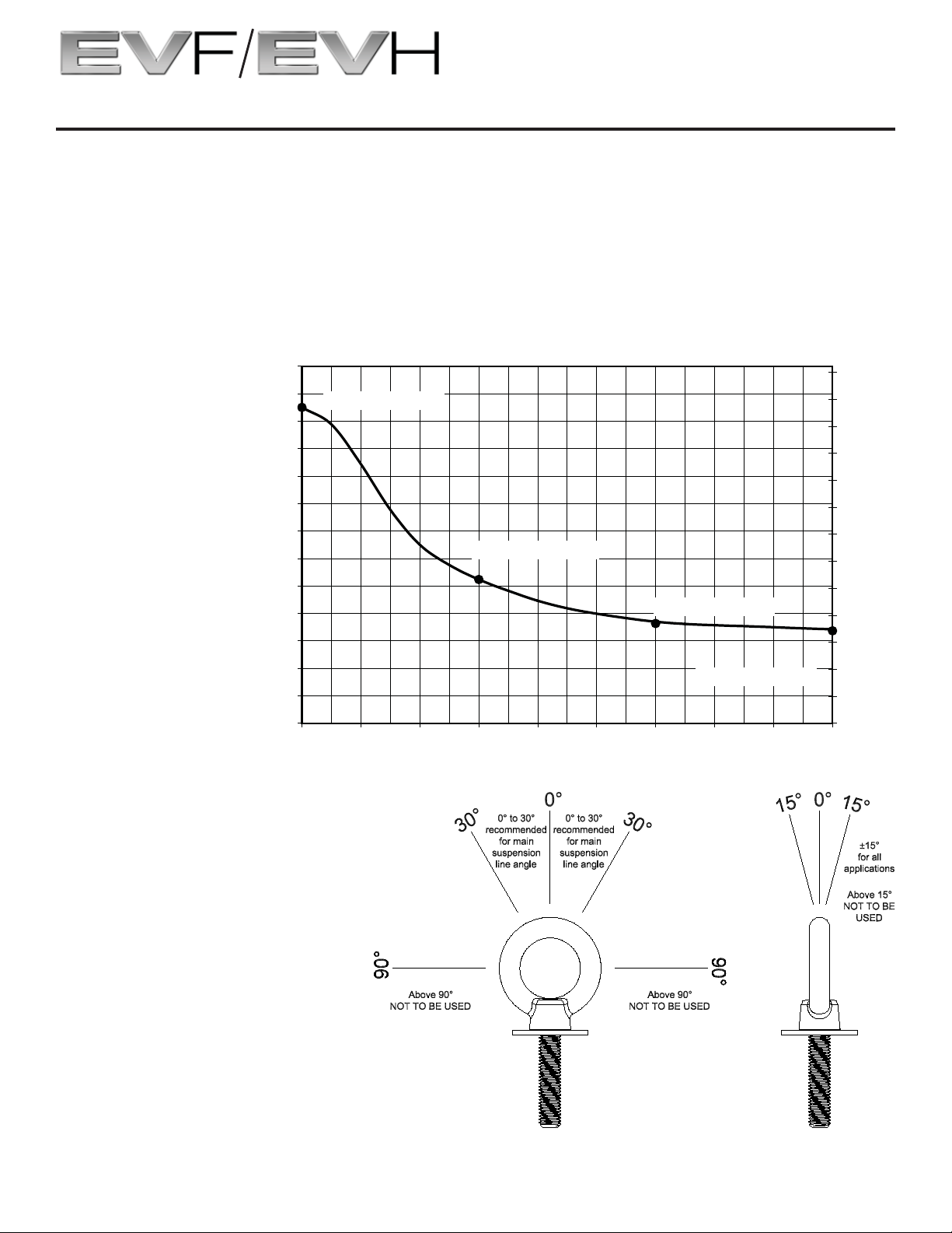
0
50
100
150
200
250
300
350
400
450
500
550
600
650
0 102030405060708090
Angle (Degrees)
Working Load Limit (lb)
0
23
45
68
91
113
136
159
181
204
227
249
272
295
Working Load Limit (kg)
575 lb (261 kg) @ 0°
262 lb (119 kg) @ 30°
185 lb (84 kg) @ 60°
171 lb (78 kg) @ 90°
6.0 Rigging-Strength Ratings and Safety Factors (cont.)
6.41 Working Load Limits for Eyebolts used with VRK Vertical Rigging Kits
Eyebolts are the most convenient way to suspend vertical clusters. Eyebolts attach to the EVF and EVH
enclosures through the integral M10-1.5 attachment points. Section 5.21 Anatomy of an EVF or EVH Flying System Using M10 Eyebolts should be reviewed at this time for more information on eyebolt alignment
and positioning on the enclosure. Table 12 shows the WLL per eyebolt with respect to the angle of the
applied load. Figure 29 shows the suspension-point angles that are referenced in the table. It is a good
idea to stay within 30° of the maximum WLL of the eyebolt (straight up position) for main suspension lines.
Table 12:
WLL for M10
eyebolts in the
EVI-M10K
eyebolt kit
Suspension line angle limits for
individual eyebolts, both in plane
of pull (left) and against plane
44
Figure 29:
of pull (right)
Electro-Voice EVF/EVH User Manual
Page 45

6.0 Rigging-Strength Ratings and Safety Factors (cont.)
6.42 Left-to-Right Vertical Cluster Angles
The suspended vertical cluster must be perpendicular (plumb) to within ±5° as shown in Figure 30.
Figure 30:
Left-to-right angle limits for a vertical cluster (angle shown exaggerated for illustration purposes)
Electro-Voice EVF/EVH User Manual 45
Page 46

6.0 Rigging-Strength Ratings and Safety Factors (cont.)
6.5 HRK Rigging Structural Ratings for Horizontal Clusters
The guidelines for simplifi ed horizontal structural ratings cover the following information:
1. Maximum height of the cluster.
2. Maximum weight of the cluster.
3. Cluster combinations, per weight and height.
4. Using tie plates for suspension.
5. Suspension-line angles for HRK rigging.
6. Symmetry of cluster.
7. Inner connection points.
8. Left-to-right horizontal cluster angles.
Using the HRK horizontal rigging kits, any combination of EVF and EVH enclosures can be assembled in
a cluster as long as the WLL, angles, and height limits are observed. For horizontal clusters, left-to-right
symmetry must also be observed to keep even loads across suspension lines.
SUSPEND HORIZONTAL CLUSTERS USING TIE PLATES ONLY, NO EYEBOLTS.
LIMITS FOR HORIZONTAL CLUSTERS ONLY
Maximum Working Load Limit Maximum Height
Three-over-Three = 980 lb (445 kg)
Two-over-Two = 634 lb (288 kg)
Max. Two Enclosures High
or 5.25 ft (160.1 cm)
Table 13:
Maximum load and maximum height for horizontal clusters
Table 14 gives a brief guide to the cluster combinations possible within the WLL of the EVF and EVH
enclosures.
LIMITS FOR HORIZONTAL CLUSTERS ONLY
Clustered Enclosures
Three enclosures over
three enclosures
Two enclosures over
two enclosures
Three enclosures across 3
Maximum Number
of Enclosures
6
4 2 See Figure 32
Minimum No. of
Suspension Lines
4
(2 per side)
4
(2 per side)
Tie Plate Angle
Restrictions
See Figure 32
See Figure 32
Two enclosures across 2 2 See Figure 32
Table 14:
Possible horizontal cluster combinations within the WLL of each enclosure
Electro-Voice EVF/EVH User Manual46
Page 47

6.0 Rigging-Strength Ratings and Safety Factors (cont.)
6.51 Using Tie Plates as Main Load-Bearing Suspension
Horizontal clusters are attached to the structure with the tie plates located on the rigging plates of the
HRK kits. The tie plates have six holes that will accept a 5/8-inch shackle or similar connector. All main
suspension lines that carry the cluster’s load should be tied to these tie plates. Both the front and rear tie
plates on the top boxes must be connected to the building structure when the cluster is installed using a
moderate trim angle as shown in Figure 31.
For purposes of stabilization, especially with the two-over-two cluster, additional stabilization points can
be helpful. These stabilization points can be used as eyebolts on the enclosures at the rear of the cluster.
Figure 31 shows typical stabilization points.
Max. Cluster Weight
634 lb (288 kg)
Max. Cluster Weight
980 lb (445 kg)
Figure 31a:
Use of tie plates in the suspension of a two-over-
two cluster using HRK rigging kits
Electro-Voice EVF/EVH User Manual 47
Use of tie plates in the suspension of a three-
over-three cluster using HRK rigging kits
Figure 31b:
Page 48

6.0 Rigging-Strength Ratings and Safety Factors (cont.)
6.52 Suspension-Line Angles for HRK Kits
Suspension-line angles are restricted to 30° off the axis of the tie plate’s center line. Figure 32 shows the
angle limitations recommended for horizontal clusters when using HRK kits.
Figure 32a:
Horizontal cluster suspension-line limit,
left-to-right, independent suspension lines
Figure 32c:
Horizontal cluster suspension-line limit,
left-to-right, bridled suspension lines
Figure 32b:
Horizontal cluster suspension-line limit,
front-to-back, independent suspension lines
Figure 32d:
Horizontal cluster suspension-line limit,
front-to-back, bridled suspension lines
Electro-Voice EVF/EVH User Manual48
Page 49

6.0 Rigging-Strength Ratings and Safety Factors (cont.)
6.53 Symmetry for Horizontal Clusters using HRK Kits
The cluster’s center of gravity is centered under the two suspension points in a two-over-two cluster (see
Figure 33a) or between the suspension points in a three-over-three cluster (see Figure 33b).
Both the cluster’s weight and center of gravity must be symmetrical about the cluster’s center line. For
individual enclosure weights and centers of gravity, refer to section 1.
Figure 33a:
Suspension of a symmetrical two-over-two
horizontal cluster using HRK horizontal
rigging kits
Electro-Voice EVF/EVH User Manual 49
Suspension of a symmetrical three-over-three
horizontal cluster using HRK horizontal
Figure 33b:
rigging kits
Page 50

6.0 Rigging-Strength Ratings and Safety Factors (cont.)
6.54 Inner Connection Points
For connection between the clusters (from bottom of top enclosure to the top of the bottom enclosure),
both the front and rear rigging plates must be connected (see Figure 34). The maximum box-to-box angle
is 45°.
WHEN RIGGING BOXTOBOX, BOTH FRONT AND REAR TIE PLATES MUST BE
CONNECTED.
Figure 34:
Box-to-Box internal connection points of a
horizontal cluster using HRK horizontal rigging kits
6.55 Left-to-Right Horizontal Cluster Angles
The suspended horizontal cluster must be perpendicular (plumb) to within ±5° as shown in Figure 35.
Figure 35:
Left-to-right angle limits for a horizontal cluster
(angle shown exaggerated for illustration purposes)
Electro-Voice EVF/EVH User Manual50
Page 51

6.0 Rigging-Strength Ratings and Safety Factors (cont.)
6.6 Ratings for Outdoor Applications with Wind Loading
Special considerations must be made for outdoor venues where wind conditions could become a
concern. High wind gusts can push the loudspeakers in a way that the suspension lines’ direction of
force can become misaligned with the plane of the eyebolt. Larger clusters pose more of a concern
because more surface area exists for the wind to act upon. Counteracting these effects requires the use
of additional suspension lines and/or stabilization lines to reduce the potential overloading of the existing
suspension lines.
IT IS THE RESPONSIBILITY OF THE USER TO ENSURE THAT ALL CLUSTERS ARE
SUSPENDED SAFELY UNDER ALL CONDITIONS. IT IS RECOMMENDED TO CONSULT A
STRUCTURAL ENGINEER WHEN WINDS ARE ANTICIPATED.
It is recommended that all loudspeakers and rigging components are inspected after high wind conditions
have occurred.
6.7 Electro-Voice Structural-Analysis Procedures
Electro-Voice maintains a structural pull-test facility in Burnsville, Minnesota, USA, which includes load
cells with digital-electronic display and recording. The load cells are calibrated annually by an independent
laboratory to a standard traceable to the United States National Bureau of Standards. This pull-test
facility is capable of pulling to destruction both individual rigging components and complete loudspeaker
systems.
Electro-Voice utilizes state-of-the-art computer modeling programs for structural analysis throughout the
development of loudspeaker systems. The computer modeling enables the complex forces in the rigging
components and enclosures to be analyzed for loudspeakers assembled into arrays and clusters in both
static and dynamic conditions.
Structural testing and computer modeling were used throughout the engineering development of all EVF
and EVH individual rigging components and complete loudspeaker systems described in this manual.
Testing and modeling involving both anticipated use and anticipated misuse were performed as part of the
analysis. Engineering prototypes were stressed to failure and designs were revised based on those test
results. Production systems and components were stressed to failure for verifi cation of the fi nal designs.
Electro-Voice EVF/EVH User Manual 51
Page 52

7.0 Rigging Inspections and Precautions
Electro-Voice EVF and EVH Loudspeaker Systems: Prior to each use, inspect the enclosures for
any cracks, deformations or missing or damaged components that could reduce enclosure strength.
Inspect the rigging plates, tie plates and stabilizer bars between enclosures for cracks, corrosion or other
deformations that could reduce their strength and integrity. Check to be sure there are no missing screws
and that all M5 connector bolts and M10 rigging bolts are securely tightened. Hardware that is bent or
showing signs of more than cosmetic surface corrosion should be replaced immediately.
Lifting Hoists: Prior to each use, inspect the lifting hoist(s) and associated hardware (including motors, if
applicable) for any cracks, deformation, broken welds, corrosion or missing or damaged components that
could reduce the hoist strength. Replace any damaged hoists. Never exceed the limitations or maximum
recommended load specifi ed by the hoist manufacturer. Always follow manufacturers’ recommendations
for operation, inspection and certifi cation. Always raise and lower the load slowly and evenly, avoiding any
rapid changes in speed or shifting loads that could result in a sudden jolt to the suspended system or the
structure from which it is suspended.
Building, Tower or Scaffold Supports: Prior to each use, the strength and load-bearing capabilities
of the building, tower or scaffold structural supports should be evaluated and certifi ed by a professional
engineer as being adequate for supporting the intended rigging system (including the loudspeakers,
grids, chain hoists and all associated hardware). Prior to each use, inspect the building, tower or
scaffold structural supports for any cracks, deformation, broken welds, corrosion or missing or damaged
components that could reduce the structural strength. Damaged structural supports should be replaced
or repaired and recertifi ed by a professional engineer. Never exceed the limitations or maximum
recommended load for the supports.
Miscellaneous Mechanical Components: Prior to each use, inspect all mechanical components
(chain, wire ropes, slings, shackles, hooks, fi ttings, ratchet straps, etc.) for any cracks, deformation, broken
welds, slipping crimps, fraying, abrasion, knots, corrosion, chemical damage, loose screws or missing or
damaged components that could reduce the maximum strength specifi ed by the component manufacturer.
Replace any damaged mechanical components immediately. Never exceed the limitations or maximum
recommended load for the mechanical components.
Electro-Voice EVF/EVH User Manual52
Page 53

8.0 Installation Instructions TK-150
Tools Required:
1. #2 Phillips screwdriver
2. 3/16 in (5 mm) fl at blade screwdriver
High Pass Filter Requirements:
The TK-150 is designed to be used with a 50 Hz
Butterworth 24 dB/octave active high-pass fi lter inserted
in the signal chain at the input to the driving amplifi er.
This fi lter protects the amplifi er from damage caused by
transformer saturation at low frequencies and allows any
number of transformers to be driven on the same line, up
to the rated power of the amplifi er. The TK-150 is capable
of delivering up to 300 Watts to the loudspeaker using
the following confi guration. Connect a 100 V drive line to
the tap labeled, DO NOT USE (150 W at 70.7 V). Insert
a Butterworth 24 dB/octave active high-pass fi lter tuned
to 66 Hz or higher in the signal chain at the input to the
driving amplifi er. Due to the band limited spectrum of the
EN54-24 simulated program signal (89 Hz - 11.2 kHz) the
EN54-24 rated power handling is certifi ed up to 400 Watts
at the100 V drive line.
4. Place the transformer in the pocket on the left.
The lead wires from the transformer should be pointed
toward you.
5. Secure the transformer mounting ears to the four (4)
input panel bosses with the four (4) #10 screws
provided. Carefully tighten the screws evenly in an
X-cross pattern to avoid warping the plastic input
panel.
Caution!
!
Failure to use the proper high-pass fi lter may
result in damage to the amplifi er.
Instructions:
To install the TK-150, do the following:
1. Remove the input panel by removing the eight (8)
screws securing it.
Make note of the original orientation prior to removing
the input panel.
2. Unplug the crossover wiring harness from the 7-pin
header.
3. Place the input panel horizontally face down with the
green circuit board on the right.
6. Unplug the 8-position jumper connector located at
right angle to the 7-pin crossover header.Plug in
the 8-position wiring harness connector from the
transformer to the 8-pin header in place of the jumper.
Notice the direction of the connector.
7. Reconnect the 7-position connector from the
crossover to the 7-pin header.
Electro-Voice EVF/EVH User Manual 53
Page 54

8.0 Installation Instructions TK-150 (cont.)
8. Reinstall the input panel in the same orientation it was
in before removal.
Do not install backwards.
9. Apply the new label (supplied) over the input
connectors.
Notice!
This product ships with two (2) input panel
labels:
i
• One (1) label is for standard use.
• One (1) label is for EN54-24 Voice Alarm
systems. Apply the TK-150 EN54 Rated label
when TK-150 is used in an EN54-24 system.
10. Confi rm the switch card is set for FULL RANGE
PASSIVE operation.
Notice!
i
Bi-Amp operation is not possible with a TK-150
installed.
11. Connect the (-) input line to the COM input terminal
and the (+) input line to the terminal corresponding
to the desired wattage in either the 70.7 V or 100 V
column.
Notice!
Each group of four (4) terminals is electrically
connected in parallel to the group of four (4)
i
terminals directly across from it. The wattages
charted in these two (2) columns represent the
wattage available from each of the three (3)
transformer taps at the designated voltage.
8.1 Transformer Ratings
Transformer:
Standard
50 Hz BW24
High-pass
70 V 100 V Z nom
37.5 W 75 W 130
75 W 150 W 65
150 W Do Not Use 33
Transformer:
89 Hz Highpass per
EN54-24
Spectrum
8.2 Approvals and Certifi cations
for fire detection and fire alarm systems for buildings
Loudspeakers type: EVF-1122S/64, EVF-1122S/66, EVF-1122S/94
EN54-24 type B certifi cation 1438-CPR-0283 (Only
available in select regions)
70 V 100 V Z nom
50 W 100 W 100
100 W 200 W 50
200 W 400 W 25
1438
Bosch Security Systems Inc.
12000 Portland Ave South, Burnsville, MN 55337, USA
Voice alarm loudspeakers
EVF-1122S/96, EVF-1122S/99, EVF-1122S/126
(BLK, WHT, PIB, PIW)
DoP: REG000104002
1438-CPR-0283
EN 54-24:2008
Caution!
This transformer is intended to aff ect only
the loudspeaker in which it is installed. When
daisy chaining additional systems, connect
!
the wires to the next system only to those
terminals directly opposite the input wires.
12000 Portland Ave South, Burnsville, MN 55337, USA
Bosch Security Systems Inc.
Improper connection may result in damage to
the transformer, successive loudspeakers, the
driving amplifi er or any combination thereof.
Notice!
i
Tighten all unused connector screws to
prevent rattles.
for fire detection and fire alarm systems for buildings
Loudspeakers type: EVH-1152D/43, EVH-1152D/64, EVH-1152D/66,
EVH-1152D/94, EVH-1152D/96, EVH-1152D/99
Voice alarm loudspeakers
1438
1438-CPR-0299
EN 54-24:2008
(BLK, WHT, PIB, PIW)
DoP: REG000666000
EN54-24 type B certifi cation 1438-CPR-0299 (Only
available in select regions)
Electro-Voice EVF/EVH User Manual54
Page 55

9.0 References
9.1 Rigging (printed)
[1] W.E. Rossnagel, L.R. Higgins & J.A. MacDonald, Handbook of Rigging for Construction and Industrial
Operations, McGraw-Hill Book Company, New York, NY, USA (1988).
[2] H. Donovan, Entertainment Rigging, http://www.riggingbooksandprograms.com, Rigging Seminars,
Seattle, WA, USA (2002)
[3] J.O. Glerum, Stage Rigging Handbook, Southern Illinois University Press, Carbondale, IL, USA (1987).
[4] P. Carter, Backstage Handbook, Broadway Press, New York, NY, USA (1988).
[5] ATM Fly-Ware™, Riggermeister Production Rigging Guide, ATM Fly-Ware™, Carson, CA, USA (1995).
[6] Wire Rope Technical Board, Wire Rope Users Manual, American Iron and Steel Institute, Stevensville,
MD, USA (1985).
[7] Broderick & Bascom Rope Company, Rigger’s Handbook, Sedalia, MO, USA (1993).
[8] MacWhite Wire Rope Company, Catalog of Tables, Data and Helpful Information, Kenosha, WI, USA
(1991).
[9] Acco Chain & Lifting Division, Chain Sling User’s Manual, Acco Corporation, York, PA, USA (1992).
[10] Newberry, W.G., Handbook for Riggers, Newberry Investments Company, Calgary, Alberta, Canada
(1989).
9.2 Mechanical Engineering (printed)
[1] R.C. Hibbeler, Engineering Mechanics Statics & Dynamics, Pearson Prentice Hall, Upper Saddle River,
NJ, USA (2005)
[2] R.C. Hibbeler, Mechanics of Materials, Pearson Prentice Hall, Upper Saddle River, NJ, USA (2005)
[3] J.L. Meriam & L.G. Kraige, Engineering Mechanics, Volume One - Statics, John Wiley & Sons, Inc.,
New York, NY, USA (1992).
[4] J.L. Meriam & L.G. Kraige, Engineering Mechanics, Volume Two - Dynamics, John Wiley & Sons, Inc.,
New York, NY, USA (1992).
[5] J.E. Shigley & C.R. Mischke, Mechanical Engineering Design, McGraw-Hill Book Company, New York,
NY, USA (1989).
9.3 Rigging (Web sites)
[1] http://www.rigging.net
[2] http://www.cmworks.com/
[3] http://catalog.thecrosbygroup.com/maininterface.htm
Electro-Voice EVF/EVH User Manual 55
Page 56

Bosch Sicherheitssysteme GmbH
Robert-Bosch-Ring 5
85630 Grasbrunn
Germany
www.boschsecurity.com
© Bosch Sicherheitssysteme GmbH, 2017
Specifi cations subject to change without notice.
2017.11 | 09 | F.01U.310.062
Bosch Security Systems, Inc
12000 Portland Avenue South
Burnsville MN 55337
USA
www.electrovoice.com
Electro-Voice EVF/EVH User Manual
 Loading...