

Page 1
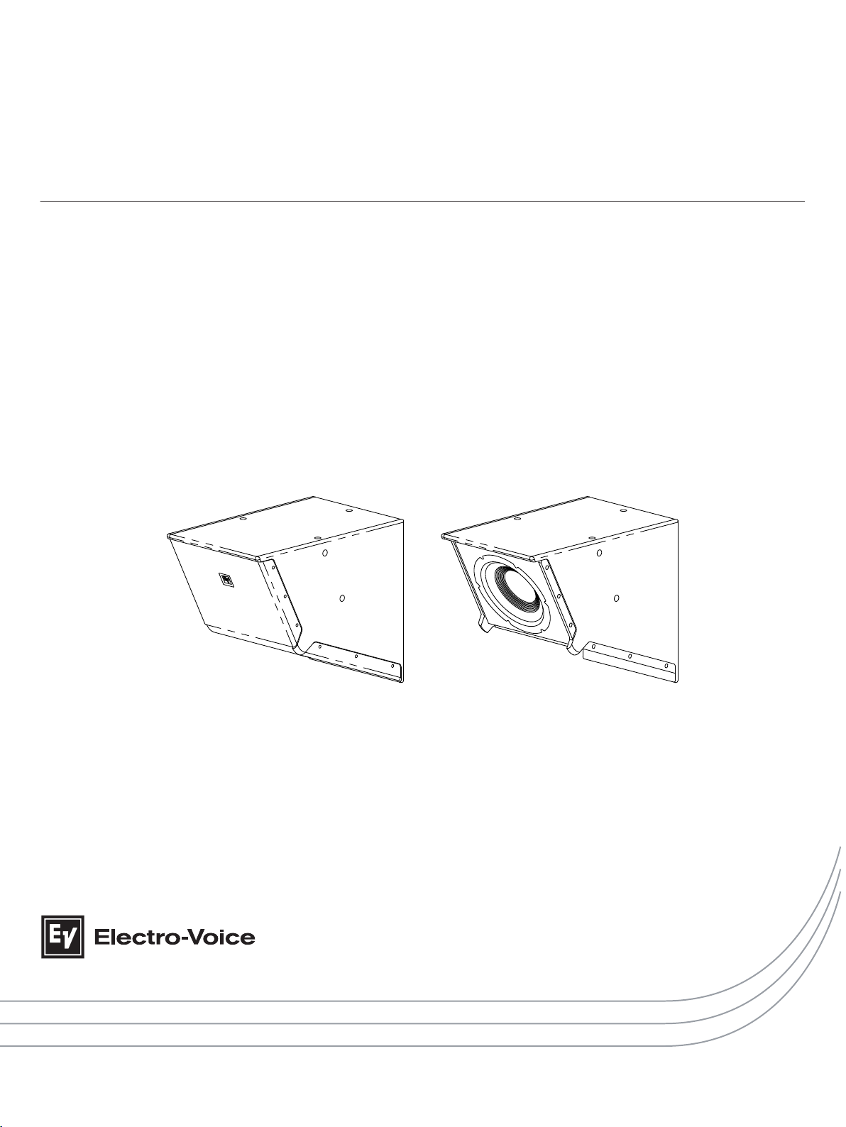
EVC Variable-Intensity Loudspeaker
EVC-1122-VIB | EVC-1122-VIW
en | Installation manual
Page 2

Page 3

Table of contents
en 3
1
1.1 Important safety instructions 4
1.2 Suspension 4
1.3 Precautions 5
1.4 Notices 5
2
3
4
4.1 Tools list 9
4.2 Preparing the EVC loudspeakers for installation 9
4.2.1 Unpacking and inspection 9
4.2.2 Scope of delivery 9
4.2.3 Recommended pre-installation procedures 9
4.3 Working with mounting accessories 10
4.3.1 Mounting with a U-bracket 10
4.3.2 Mounting with rigging points 11
5
6
6.1 Low impedance connection 16
7
8
8.1 Installation of TK-150 transformer for passive crossovers 20
8.2 Input panel covers 23
9
9.1 Rigging (printed) 24
9.2 Mechanical engineering (printed) 24
9.3 Rigging (websites) 24
Safety 4
Introduction 6
Planning the installation and aiming of the EVC-1122-VI loudspeaker 8
Installation 9
Rigging strength ratings and safety factors 13
Electrical connection 16
Technical data 18
Accessories (optional) 20
References 24
Electro-Voice Installation manual 2018.01 | 01 | F.01U.345.997
Page 4
!
!
EVC Variable-Intensity Loudspeaker
1
1.1
1.2
Safety
Important safety instructions
1. Read these instructions.
2. Keep these instructions.
3. Heed all warnings.
4. Follow all instructions.
5. Clean only with a dry cloth.
6. Do not install near any heat sources such as radiators, heat registers, stoves, or other
apparatus (including amplifiers) that produce heat.
Suspension
Warning!
Suspending any object is potentially dangerous and should only be attempted by individuals
who have a thorough knowledge of the techniques and regulations of suspending objects
overhead. Electro-Voice strongly recommends that loudspeakers be suspended taking into
account all current national, federal, state, and local laws and regulations. It is the
responsibility of the installer to ensure all loudspeakers are safely installed in accordance
with all such requirements. When loudspeakers are suspended, Electro-Voice strongly
recommends the system be inspected at least once per year or as laws and regulations
require. If any sign of weakness or damage is detected, remedial action should be taken
immediately. The user is responsible for making sure the wall, ceiling, or structure is capable
of supporting all objects suspended overhead. Any hardware used to suspend a loudspeaker
not associated with Electro-Voice is the responsibility of others.
Caution!
It is the installer's responsibility to determine and use the proper mounting hardware for
the wall construction type.
Disregarding this caution could result in damage to the product and personal injuries may
occur.
Redundant seismic safety cable
As an added safety measure, when the loudspeaker is suspended or mounted, the user should
connect an unused rigging point to a solid structural point using an appropriate safety cable.
The cable should have a small amount of slack, but no more than ¾ inch.
2018.01 | 01 | F.01U.345.997 Installation manual Electro-Voice
Page 5
!
!
!
en 5
1.3
1.4
Precautions
These Electro-Voice loudspeakers were designed for use in an environment with
ambient temperatures between -20°C (-4°F) and +50°C (122°F).
These Electro-Voice loudspeakers are not rated for continuous outdoor
conditions. However, they may be exposed to occasional short-term rain, water,
or high humidity.
Electro-Voice loudspeakers are easily capable of generating sound pressure
levels sufficient to cause permanent hearing damage to anyone within normal
coverage distance. Caution should be taken to avoid prolonged exposure to
sound pressure levels exceeding 90 dB.
Notices
Old electrical and electronic appliances
Electrical or electronic devices that are no longer serviceable must be collected separately and
sent for environmentally compatible recycling (in accordance with the European Waste
Electrical and Electronic Equipment Directive).
To dispose of old electrical or electronic devices, you should use the return and collection
systems put in place in the country concerned.
Copyright and disclaimer
All rights reserved. No part of this document may be reproduced or transmitted in any form by
any means, electronic, mechanical, photocopying, recording, or otherwise, without the prior
written permission of the publisher. For information on getting permission for reprints and
excerpts, contact Electro-Voice.
All content including specifications, data, and illustrations in this manual are subject to change
without prior notice.
Electro-Voice Installation manual 2018.01 | 01 | F.01U.345.997
Page 6

EVC Variable-Intensity Loudspeaker
2
Introduction
EVC-1122-VI Variable Intensity loudspeaker
The EVC-1122-VI Variable Intensity loudspeaker is a two-way design with a unique compound
waveguide that can evenly cover a defined rectangular audience area with almost no variation
in sound quality and minimal change in level. It can be used as a full-range system or as a
mid-/high-frequency enclosure matched to the EVC-1181S subwoofer. EVC loudspeakers are
voiced so that they can be seamlessly used in systems with other EV-Innovation models (EVA,
EVF, and EVH), so the EVC-1122-VI can be used in conjunction with any of these, including the
other two-way systems in the EVC series.
The high frequency section the EVC-1122-VI comprises a single 1¼-inch pure titanium dome
compression driver directly coupled to a specialized waveguide that combines the
functionality of long-throw and short-throw horns in a single acoustic device. The low
frequency section employs a high-output woofer that was developed using state-of-the-art,
computer-aided optimization to provide low distortion, high efficiency, and maximum
intelligibility at high sound pressure levels. The passive crossover implements an enhanced
fourth-order design with slopes of greater than 24 dB per octave for smooth off-axis response
and improved definition through the critical vocal range.
The EVC-1122-VI enclosure is constructed of 15-mm plywood and finished with EVCoat for
enhanced durability. The loudspeaker has been designed with M10 suspension points as well
as attachment points for an optional U-bracket. EVC series loudspeakers accept wire gauges
up to 10 AWG. The input panel also accepts optional covers with NL4-type connectors or
weatherized gland-nuts.
For 70V/100V operation, the input panel has an internal landing pad for mounting EV's highquality TK-150 audio transformer. When the transformer is installed, it engages EV's patented
Automatic Saturation Compensation (ASC), which preserves low frequency performance while
presenting a stable load to the amplifier - regardless of the number of speakers connected in
parallel. As a result, EVC loudspeakers - including the subwoofers - sound virtually identical,
whether they are used with a transformer or without.
Constant directivity vs variable intensity
Most modern loudspeaker systems designed for installation are based on a constantdirectivity approach. They are designed to provide a consistent, smooth transition from the
low-frequency woofer to the high-frequency section. Constant-directivity systems typically
have symmetrical vertical coverage patterns and constant horizontal coverage. Systems built
around single or multiple constant-directivity loudspeakers are widely used in high quality
installed sound reinforcement systems. While many implementations deliver excellent
performance, one key drawback is that SPL can vary significantly over the audience area - from
front-to-back and left-to-right. The front-to-back variation can be minimized by tilting the horn
further back or by adding appropriately delayed fill speakers, but these remedies often result
in noticeable slap echo, decreased dynamic range, and poor intelligibility because of excessive
excitation of the reverberant field.
The EVC-1122-VI attacks these shortcomings by producing a wide near-field coverage angle
and a narrow far-field angle from a single loudspeaker system. The 12-inch woofer is installed
in the enclosure at an angle so that its central axis is directed toward the last row of the
audience, using the natural off-axis roll-off the driver to deliver more consistent level to every
seat. And the unique, asymmetrical waveguide replaces a short-throw/long-throw horn
combination to evenly cover the audience area with a single device. The resulting coverage
characteristic ensures a well-defined rectangular listening area, and the more gradual intensity
change compensates for the drop in SPL over the longer distance to the back of the room. The
2018.01 | 01 | F.01U.345.997 Installation manual Electro-Voice
Page 7

en 7
size of the coverage area is determined by the height at which the loudspeaker is mounted, as
well as the vertical angle at which the system is aimed. This single-box solution reduces
material costs and labor time while increasing performance with higher intelligibility and more
uniform coverage.
In summary, the major advantages of the EVC-1122-VI are:
▪ Rectangular coverage pattern. Traditional waveguides deliver an elliptical pattern to the
floor. VI horns deliver a rectangular pattern, which helps to fill in the corners of the room.
No more costly delay lines.
▪ Even SPL front-to-back. The unique, patented throat and flare structure of the VI
waveguide delivers more consistent sound levels throughout the room, eliminating ear
strain at the back of the seating area and painful ears at the front.
▪ Greater Intelligibility. VI waveguides deliver sound to fill only the floor plan, providing
uniform direct-field SPL and an order of magnitude less energy into the reverberant field.
This provides an increase in mid- to high-frequency intelligibility of 6 dB in most
applications.
▪ One horn replaces two. With VI technology we’ve eliminated the destructive interference
which occurs between long- and short-throw loudspeakers. We’ve also eliminated the
cost of a properly designed two-box system, which needs to include another power
amplifier channel for proper power control and impedance matching.
▪ Labor savings in the box. Variable Intensity systems will fly more conveniently and in less
time than many competitive products. In addition, less time is spent on aiming and
repositioning. This will save you additional money.
Numbering scheme
The numbering scheme for EVC models is similar to that of other EV-Innovation loudspeakers.
It denotes the number and diameter of the woofers, the number of passbands, the coverage
pattern, and the enclosure color. For example, the EVC-1122-VIB employs a single 12-inch
woofer in a two-way configuration with our unique, compound, Variable Intensity waveguide,
and is finished in black EVCoat. Similarly, the EVC-1181S-W uses a single 18” woofer to cover
a single passband. In other words, it is a subwoofer or low-frequency system in a white
enclosure.
Finishes and colors available
EVC-1122-VI loudspeakers are finished in tough EVCoat. Unlike other EVC models, there are no
weatherized versions of the variable-intensity speaker. Like all EVC systems, the EVC-1122-VI
is available in black or white.
To find current user documentation visit our product related information at
www.electrovoice.com.
Electro-Voice Installation manual 2018.01 | 01 | F.01U.345.997
Page 8
EVC Variable-Intensity Loudspeaker
3
Planning the installation and aiming of the EVC-1122-VI loudspeaker
The remarkably even coverage of the EVC-1122-VI is due not only to the unique, compound
waveguide, but is also the result of the woofer mounting angle, the spacing between woofer
and horn, and the enclosure configuration. The speaker is designed to be mounted with the
waveguide on the bottom and the woofer facing forward. This means that when installed in
the proper orientation, the grille will cover the bottom and the angled front baffle. Another
visual indicator for confirming that the loudspeaker is oriented correctly is that the EV logo is
attached to the grille in front of the woofer, and should therefore be on the front face of the
loudspeaker when viewed head on. The largest rectangular surface of the speaker should face
upward. Note that the waveguide cannot be rotated, and the loudspeaker will only exhibit its
characteristic, predictable coverage when installed as described above.
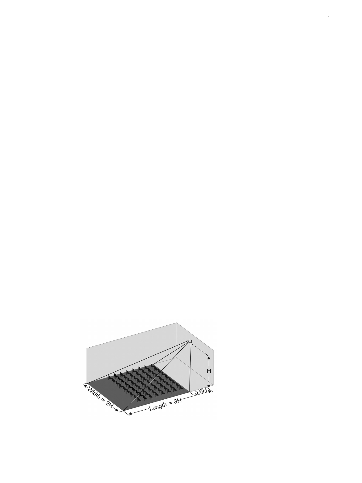
The size of the rectangular area that the loudspeaker will cover is determined by its mounting
height, as measured from the bottom rear of the loudspeaker. The horizontal coverage pattern
will maintain a width that is approximately twice as wide as the mounting height
measurement; the vertical throw will be about three times the mounting height. There is a
small area of reduced coverage on the floor directly in front of the loudspeaker, which will
help increase the gain-before-feedback margin in the area where the presenter or musicians
will likely be located. Full coverage starts at a distance equal to 6/10 of the mounting height.
These combined coverage parameters can be approximated with a simple 3:2:1 rule that
makes it easy to estimate coverage during the design phase of a project.
You can extend or reduce the vertical throw by adjusting the aiming angle of the loudspeaker.
Note that this will change both the front and rear boundaries of the coverage area, since both
are affected by aiming. The new vertical coverage extremes are defined by the following
equations:
Beginning of vertical coverage = tan(31.0° ± tilt angle) x mounting height
Limit of vertical coverage = tan(71.6° ± tilt angle) x mounting height
These values can easily be determined with the help of a scientific calculator with
trigonometric functions. The tilt angle should be entered in degrees, but the mounting height
can be in either English or metric units. Vertical aiming has no material effect on horizontal
coverage over the audience area.
Figure 3.1: Coverage area determined by mounting height and angle
2018.01 | 01 | F.01U.345.997 Installation manual Electro-Voice
Page 9

en 9
4
4.1
4.2
4.2.1
Installation
Tools list
The tools required to prepare the system for installation are:
▪ 3/16-inch (5 mm) flat blade screwdriver
▪ 6 mm Allen wrench
▪ Phillips #2 screwdriver
Preparing the EVC loudspeakers for installation
Unpacking and inspection
Carefully open the packaging and take out the loudspeaker. Inspect the loudspeaker's
enclosure for any damage that might have happened during transportation. Each loudspeaker
is examined and tested in detail before leaving the manufacturing site. Please inform the
transport company immediately if the loudspeaker shows any damage. Being the addressee,
you are the only person who can claim damages in transit. Keep the cardboard box and all
packaging materials for inspection by the transport company.
Keeping the cardboard box including all packing materials is also recommended, even if the
loudspeaker shows no external damage.
When shipping the loudspeaker, make sure to always use its original box and packaging
materials. By packing the loudspeaker exactly as it was packed by the manufacturer, you will
guarantee optimum protection from transport damage.
4.2.2
4.2.3
Scope of delivery
Keep the original invoice that states the purchase/delivery date in a safe place.
Recommended pre-installation procedures
For any sound system, certain checks made at the installer’s place of business can prevent
expensive on-site delays. EV recommends that you take the following steps:
1. Unpack all loudspeakers in the shop.
2. Check for proper model numbers.
3. Check the overall condition of the loudspeakers.
4. Check for continuity at the loudspeaker inputs.
Once you are on site and the loudspeakers are connected, it is a good idea to check again for
continuity at the power-amplifier end of each cable run.
Electro-Voice Installation manual 2018.01 | 01 | F.01U.345.997
Page 10

!
!
EVC Variable-Intensity Loudspeaker
4.3
4.3.1
Working with mounting accessories
Warning!
Suspending any object is potentially dangerous and should only be attempted by individuals
who have a thorough knowledge of the techniques and regulations of suspending objects
overhead. Electro-Voice strongly recommends that loudspeakers be suspended taking into
account all current national, federal, state, and local laws and regulations. It is the
responsibility of the installer to ensure all loudspeakers are safely installed in accordance
with all such requirements. When loudspeakers are suspended, Electro-Voice strongly
recommends the system be inspected at least once per year or as laws and regulations
require. If any sign of weakness or damage is detected, remedial action should be taken
immediately. The user is responsible for making sure the wall, ceiling, or structure is capable
of supporting all objects suspended overhead. Any hardware used to suspend a loudspeaker
not associated with Electro-Voice is the responsibility of others.
Mounting with a U-bracket
Caution!
It is the installer's responsibility to determine and use the proper mounting hardware for
the wall construction type.
Disregarding this caution could result in damage to the product and personal injuries may
occur.
The EVC-1122-VI can be mounted on a wall or ceiling with an accessory U Bracket. The bracket
attaches to the sides of the loudspeaker in the same axis as the center of gravity to simplify
aiming and reduces the tendency to drift from the correct angle after installation.
Figure 4.1: EVC U-bracket installed vertically
EVC U-Bracket
EVC-UB3 is an optional U-Bracket kit for
mounting a single EVC-1122-VI system to a
wall or ceiling.
Available in black or white:
▪ EVC-UB3-BLK
▪ EVC-UB3-WHT
Table 4.1: EVC U-Bracket mounting models
For more information, see EVC-UB3 Adjustable U-Mount Mounting Bracket Installation
Instructions (F.01U.349.928).
2018.01 | 01 | F.01U.345.997 Installation manual Electro-Voice
EVC loudspeaker models
The EVC-UB3 fits EVC-1122-VI models:
EVC-1122-VIB
EVC-1122-VIW
Page 11

!
en 11
4.3.2
Mounting with rigging points
The EVC-1122-VI can also be suspended from the three insert points on the top of the
loudspeaker enclosure. A safety cable should always be attached to one of the rigging points.
EVC loudspeakers are designed to be installed individually. There are no factory-approved
accessories for creating clusters by connecting an EVC loudspeaker to any other loudspeaker.
Figure 4.2: Suspending EVC systems, including a safety cable
Eyebolt accessory kits
EVC loudspeakers do not ship with eyebolts. To suspend the speaker, it is necessary to order
one of the accessory eyebolt kits (sold separately).
▪ EBK-M10-3PACK: optional eyebolt kit, consisting of three M10 shoulder eyebolts and
three fender washers, used when eyebolts are needed to suspend any of the full-range
EVC loudspeakers. For more information see, EBK-M10 Eyebolt Attachment Kit
Installation Instructions (F.01U.303.870).
Installing the eyebolts
Caution!
No eyebolt should be mounted in the sides of an EVC enclosure in order to suspend a system.
Doing so may result in damage to the enclosure, leading to installation failure, and personal
injury.
Figure 4.3: Eyebolts installed incorrectly in the sides of an enclosure in order to suspend it from above
Electro-Voice Installation manual 2018.01 | 01 | F.01U.345.997
Page 12

A
!
EVC Variable-Intensity Loudspeaker
All hardware supplied by the user must be rated for overhead lifting to suspend the
loudspeaker system.
To install the eyebolts, do the following:
1. Remove the three M10 flat-head bolts (A) from the fly points on the top of the enclosure.
2. Screw the lifting eyebolt with fender washer into the threaded attachment point until
the fender washer makes contact with the enclosure.
Never install the eyebolt without the washer included with the eyebolt kit.
3. Finger tighten the eyebolt until the correct alignment position is obtained.
A maximum of one complete turn.
4. Install a safety cable.
Eyebolts orientated in the plane of pull
Caution!
Eyebolts must be fully seated and oriented in the plane of pull. Always use the fender washer
included with the eyebolt kit to distribute the load on the enclosure.
Excessive tightening of the eyebolt with a wrench, screwdriver or other tool, can result in a
system failure and possible injury.
Figure 4.4: Fully seated eyebolts with washers, with correct orientation in the plane of pull (Correct; left,
Incorrect; right)
2018.01 | 01 | F.01U.345.997 Installation manual Electro-Voice
Page 13

!
en 13
5
Rigging strength ratings and safety factors
Working load limit and safety-factor definitions
The structural ratings for all EVC rigging components and loudspeaker systems are based on
test results in which parts were stressed to failure. Manufacturers typically present the
structural-strength ratings of mechanical components or systems as either the Working Load
Limit (WLL) or the ultimate-break strength. Electro-Voice chooses to present the structuralload ratings of loudspeaker systems as the WLL. The WLL rating represents the maximum load
that should ever be applied to a mechanical component or system.
Warning!
Never exceed the limitations or maximum recommended working load for Electro-Voice
loudspeakers.
Disregarding this warning could result in serious injury or death.
The WLL for the rigging components and loudspeaker systems described in this manual is
calculated with a 10:1 safety factor, which exceeds the minimum 8:1 safety factor normally
specified by Electro-Voice. The safety factor is defined as the ratio of the ultimate-break
strength divided by the WLL, where the ultimate-break strength represents the force at which
a part will structurally fail. For example, if a part has a WLL of 100 lb (45.4 kg), it would not
structurally fail until a force of at least 1,000 lb (453.6 kg) was applied, based on a 10:1 safety
factor. However, the user should never apply a load to that part that exceeds 100 lb (45.4 kg).
The safety factor provides a margin of safety above the WLL to accommodate normal dynamic
loading and normal wear.
Cautions for working load limits and safety factors
The WLL defined by the manufacturer of any rigging component should never be exceeded.
Other manufacturers of rigging components may base their WLL on safety factors other than
10:1. For example, 5:1 safety factors are fairly common among rigging manufacturers because
many regulatory agencies call for a minimum safety factor of 5:1.
When an EV loudspeaker system is installed where local regulations only require a safety
factor of 5:1, Electro-Voice insists that the WLL of the loudspeaker rigging never be exceeded
and that an 10:1 safety factor be maintained.
The user is cautioned that some local regulations may require safety factors higher than 10:1.
In those circumstances, Electro-Voice insists that the user maintain the higher safety factor as
required by the local regulations throughout the entire loudspeaker installation. It is the
responsibility of the user to make sure that any loudspeaker installation meets all applicable
local, state or federal safety regulations.
Recommended practice for eyebolts
Eyebolts can be used to suspend individual loudspeakers when attached through the integral
M10 attachment points. It is a good idea to orient the suspending cable so that it hangs within
30° of the straight-up position in the plane of pull (left illustration), and within 15° against the
plane of pull (right illustration).
Electro-Voice Installation manual 2018.01 | 01 | F.01U.345.997
Page 14

0°
30°
90°
30°
90°
0°
15°
15°
A
B
C
D
A
B
EVC Variable-Intensity Loudspeaker
Suspension line angle limits for individual eyebolts
Figure 5.1: Suspension line angle limits for individual eyebolts, both in plane of pull (left) and against plane
of pull (right)
A
Above 90° NOT TO BE USED
B 0° to 30° recommended for main suspension line angle
C ±15° for all applications
D Above 15° NOT TO BE USED
Suspension line angles
Refer to Working load limit for M10 eyebolts and EVC loudspeakers, page 14 and Suspension
line angle limits for individual eyebolts, page 14 for specific eyebolt angle and weight limitations
when using eyebolt suspension. These limits are not to be exceeded under any circumstances.
If a safety factor higher than 10:1 is required, the angle limits for each eyebolt may actually
decrease to a number less than what is shown in Suspension line angle limits for individual
eyebolts, page 14.
Working load limit for M10 eyebolts and EVC loudspeakers
Model
EVC-1082 30 lb 30 lb
EVC-1122-64 or EVC-1122-95 55 lb 55 lb
EVC-1122-VI 55 lb 55 lb
EVC-1152 65 lb 65 lb
EVC-1181S 85 lb 85 lb
Table 5.1: WLL for M10 eyebolts and EVC loudspeakers
Always ensure that the suspension line is in the plane of the eyebolt, as shown in Eyebolts
orientated in the plane of pull, page 12. Readjust the eyebolt during the installation if necessary
to maintain this alignment.
2018.01 | 01 | F.01U.345.997 Installation manual Electro-Voice
WLL Each Point (10:1) WLL Each Speaker (10:1)
Page 15

60º
MAX
60º
MAX
5º
MAX
Eyebolt suspension-line angle limit
Figure 5.2: All-eyebolt suspension-line angle limit, independent (left) or bridled (right) suspension lines
Left-to-right all-eyebolt suspension angles
The suspended all-eyebolt cluster must be perpendicular (plumb) to within ±5°.
en 15
Figure 5.3: Left-to-right angle limits for an all-eyebolt suspension (visual angle shown exaggerated for
illustration purposes)
Electro-Voice Installation manual 2018.01 | 01 | F.01U.345.997
Page 16

EVC Variable-Intensity Loudspeaker
6
6.1
Electrical connection
Low impedance connection
All EVC full-range systems are passive, meaning that the internal crossover/equalizer network
sends low frequencies to the woofer and high frequencies to the compression-driver/
waveguide combination. In addition, the network tailors the frequency response and level of
each individual driver so that the overall frequency response of the loudspeaker is essentially
flat over its intended range of operation. There is no bi-amp option for EVC full-range
loudspeakers.
Figure 6.1: EVC input panel
The screw terminals on the input panel will accept wire gauges as large as AWG 10. There are
two pairs of terminals labeled + and -. A speaker-level audio signal should be connected to one
of these +/- pairs. The other +/- pair can be used to connect one or more additional
loudspeakers in parallel, as long as the combined load impedance does not drop too low for
the amplifier to operate reliably. When the TK-150 audio transformer is installed in an EVC
loudspeaker, the ASC feature will automatically keep the impedance of each loudspeaker in a
safe range. The two pairs of connections marked THRU are wired as pass-through connections
for a separate audio signal.
Optional speaker processing
Once an EVC loudspeaker is installed in a venue a digital signal processor (DSP) will typically
be used to adjust the in-room frequency response. In addition, the DSP should be used to
provide the high-pass filters recommended to protect the EVC-1122-VI from overdrive at
frequencies below its operating range. Failure to do so could damage the low-frequency driver
if the system is subjected to high-level signals below its operating range. The recommended
high-pass filter frequencies for infrasonic protection of the EVC-1122-VI is:
2018.01 | 01 | F.01U.345.997 Installation manual Electro-Voice
Page 17

en 17
Model Recommended high-pass frequency (minimum)
EVC-1122-VI 45 Hz, 4th-order high-pass (24dB/octave)
Table 6.1: Recommended high-pass filter frequencies for infrasonic protection of EVC-1122-VI systems
The recommended high-pass filter can be implemented in a stand-alone DSP loudspeaker
controller or in the processing section of a DSP-enabled amplifier. L Series and C Series
amplifiers from Dynacord are recommended for use with EVC loudspeakers because they can
also implement model-specific processing that optimizes loudspeaker performance. EVC
loudspeaker settings can also be implemented in any IRIS-Net compatible digital signal
processor.
Electro-Voice Installation manual 2018.01 | 01 | F.01U.345.997
Page 18

EVC Variable-Intensity Loudspeaker
7
Technical data
Frequency response (-3 dB)
Frequency range (-10 dB)
Rec. high-pass frequency: 45 Hz
Passive crossover frequency: 1.6 kHz
1, 3
: 70 Hz - 20 kHz
1, 3
: 50 Hz - 25 kHz
Axial sensitivity1: 95 dB (1 W/1 m)
Max. calculated SPL: 126 dB
1
Power handling2: 300 W (Continuous), 1200 W (Peak)
Nominal impedance: 8 Ω
Minimum impedance: 7 Ω
LF transducer: EVS-12M
HF transducer: DH-3
Connectors: Dual four-pin 10 AWG Phoenix/Euro Block
screw-terminals
Enclosure: 15-mm plywood with EVCoat
Environmental: IEC 60529, IP44
Dimensions (H x W x D): 528 mm x 411 mm x 648 mm
Shipping weight: 24.4 kg (53.9 lb)
1
Full-space measurement.
2
EIA RS-426A, tested for eight hours.
3
With recommended preset.
Grille: 18 GA powder-coated steel with rotatable logo
Suspension: (8) M10 suspension points
Color: Black or white
(20.78 in x 16.18 in x 25.50 in)
Net weight: 21.8 kg (48.1 lb)
2018.01 | 01 | F.01U.345.997 Installation manual Electro-Voice
Page 19

69°
63°
276.6 mm
[10.89 in]
411.0 mm
[16.18 in]
527.8 mm
[20.78 in]
647.6 mm
[25.50 in]
202.0 mm
[7.95 in]
Frequency response and impedance: Dimensions:
en 19
Electro-Voice Installation manual 2018.01 | 01 | F.01U.345.997
Page 20

!
EVC Variable-Intensity Loudspeaker
8
8.1
Accessories (optional)
Installation of TK-150 transformer for passive crossovers
Tools required:
▪ Phillips #2 screwdriver
▪ 3/16-inch (5 mm) flat blade screwdriver
High Pass Filter Requirements:
Caution!
Failure to use the proper high-pass filter may result in damage to the amplifier.
The TK-150 audio transformer is designed to be used with Butterworth 24 dB/octave high-pass
filter inserted in the signal chain at the input to the amplifier. The filter corner frequency
should be set at 50 Hz for full-range models and at 40 Hz for the EVC-1181S subwoofer. This
filter, in conjunction with the Automatic Saturation Compensation (ASC) feature, protects the
amplifier from damage caused by transformer saturation at low frequencies and allows any
number of transformers to be driven on the same 70V or 100V line, up to the rated power of
the amplifier. At the same time, the ASC circuit preserves the low-frequency extension of the
system by adding incremental filtering only to the extent required by the current level in the
loudspeaker. Following the parameters below, the TK-150 is capable of delivering up to 300
Watts to the loudspeaker by connecting a 100V drive line to the tap labeled DO NOT USE
(150W at 70.7V) if a Butterworth 24 dB/octave active high-pass filter tuned to 66 Hz or higher
is inserted in the signal chain at the input to the driving amplifier.
Notice!
Each group of four terminals is electrically connected in parallel to the group of four terminals
directly across from it.
The wattages charted in these two columns represent the wattage available from each of the
three transformer taps at the designated voltage.
70V 100V Z nom
Transformer: (Standard 50 Hz BW20
High-pass)
Transformer: 89 Hz High-pass per
EN54-24 spectrum
Table 8.1: Transformer ratings and taps
37.5 W 75 W 130 Ω
75 W 150 W 65 Ω
150 W Do Not Use 33 Ω
50 W 100 W 100 Ω
100 W 200 W 50 Ω
200 W 400 W 25 Ω
2018.01 | 01 | F.01U.345.997 Installation manual Electro-Voice
Page 21

!
!
Installing the TK-150 transformer
Caution!
This transformer affects only the loudspeaker to which it is installed.
Improper connection may result in damage to the transformer, successive loudspeakers, the
driving amplifier or any combination of these units.
Caution!
When daisy chaining additional systems, connect the wires to the next system only to those
terminals directly opposite the input wires.
Improper connection may result in damage to the transformer, successive loudspeakers, the
driving amplifier or any combination thereof.
Notice!
Tighten all unused connector screws to prevent rattles.
Notice!
The TK-150 ships with two input panel labels, one label is for standard use, and one label is
for EN54-24 Voice alarm systems.
Apply the TK-150 EN54 rated label when TK-150 is used in an EN54-24 system.
To install the TK-150, do the following:
1. Remove the input panel by removing the eight screws securing it.
Make note of the original orientation prior to removing the input panel.
2. Place the input panel horizontally face down with the green circuit board on the right.
en 21
3. Place the transformer in the pocket on the left.
The lead wires from the transformer should be pointed toward you.
Electro-Voice Installation manual 2018.01 | 01 | F.01U.345.997
Page 22

EVC Variable-Intensity Loudspeaker
4. Secure the transformer mounting ears to the four input panel bosses with the four #10
screws (A) provided.
Carefully tighten the screws evenly in an X-cross pattern to avoid warping the plastic input
panel.
5. Unplug the 8-position jumper connector located at right angle to the 7-pin crossover
header.
6. Plug in the 8-position wiring harness connector (B) from the transformer to the 8-pin
header in place of the jumper.
Notice the direction of the connector.
7. Reinstall the input panel in the same orientation it was in before removal.
Do not install backwards.
8. Apply the new label (supplied) over the input connectors.
9. Connect the (-) input line to the COM input terminal and the (+) input line to the terminal
corresponding to the desired wattage in either the 70.7V or 100V column.
Automatic Saturation Compensation
When the TK-150 transformer is installed in an EVC loudspeaker, it engages EV’s patented
Automatic Saturation Compensation (ASC), which preserves low frequency performance while
presenting a stable load to the amplifier - regardless of the number of speakers connected in
parallel. As a result, EVC loudspeakers - including the subwoofers - sound virtually identical,
whether they are used with a transformer or without.
2018.01 | 01 | F.01U.345.997 Installation manual Electro-Voice
Page 23

en 23
8.2
Input panel covers
For all EVC loudspeakers. Electro-Voice offers input panel covers that protect the electrical
connections from moisture in outdoor installations or give the user of using quick-release NL4
type speaker connectors.
CDG: optional dual-gland-nut input-panel cover to protect the input connections
from water. Note that this cover is supplied with the PI versions.
CSG: optional single-gland-nut input-panel cover to protect the input connections
from water.
CDNL4: optional input-panel cover equipped with dual Neutrik Speakon NL4M
connectors, providing a quick-disconnect -alternative to the standard Phoenix
screw-terminal input connectors.
These are the same input panel accessories that fit all EV-Innovation loudspeaker models.
Electro-Voice Installation manual 2018.01 | 01 | F.01U.345.997
Page 24

EVC Variable-Intensity Loudspeaker
9
9.1
References
Rigging (printed)
[1] W.E. Rossnagel, L.R. Higgins & J.A. MacDonald, Handbook of Rigging for Construction and
Industrial Operations, McGraw-Hill Book Company, New York, NY, USA (2009).
[2] H. Donovan, Entertainment Rigging, http://www.riggingbooksandprograms.com, Rigging
Seminars, Seattle, WA, USA (2002).
[3] J.O. Glerum, Stage Rigging Handbook, Southern Illinois University Press, Carbondale, IL,
USA (2007).
[4] P. Carter, Backstage Handbook, Broadway Press, New York, NY, USA (1994).
[5] J. A. Klinke, Rigging Handbook, ACRA Enterprises, Inc., Stevensville, MI, USA (2012).
[6] Wire Rope Technical Board, Wire Rope Users Manual, American Iron and Steel Institute,
Stevensville, MD, USA (2005).
[7] D. L. Hall, Rigging Math Made Simple, Spring Knoll Press, Johnson City, TN (2014).
[8] Newberry, W.G., Handbook for Riggers, Newberry Investments Company, Calgary, Alberta,
Canada (1989).
--------------------
1. *All other trademarks are property of their respective owners.
9.2
9.3
Mechanical engineering (printed)
[1] R.C. Hibbeler, Engineering Mechanics Statics & Dynamics, Pearson Prentice Hall, Upper
Saddle River, NJ, USA (2012).
[2] R.C. Hibbeler, Mechanics of Materials, Pearson Prentice Hall, Upper Saddle River, NJ, USA
(2012).
[3] J.L. Meriam & L.G. Kraige, Engineering Mechanics, Volume One - Statics, John Wiley &
Sons, Inc., New York, NY, USA (2011).
[4] J.L. Meriam & L.G. Kraige, Engineering Mechanics, Volume Two - Dynamics, John Wiley &
Sons, Inc., New York, NY, USA (2012).
[5] J.E. Shigley & C.R. Mischke, Mechanical Engineering Design, McGraw-Hill Book Company,
New York, NY, USA (2014).
Rigging (websites)
[1] http://www.rigging.net
[2] http://www.cmworks.com/
2018.01 | 01 | F.01U.345.997 Installation manual Electro-Voice
Page 25

Page 26

Page 27

Page 28

Bosch Sicherheitssysteme GmbH
Robert-Bosch-Ring 5
85630 Grasbrunn
Germany
www.boschsecurity.com
© Bosch Sicherheitssysteme GmbH, 2018
Bosch Security Systems, Inc
12000 Portland Avenue South
Burnsville MN 55337
USA
www.electrovoice.com
 Loading...