

Page 1
EVA-AM
Attenuation Module
for EVA Loudspeakers
Installation Instructions
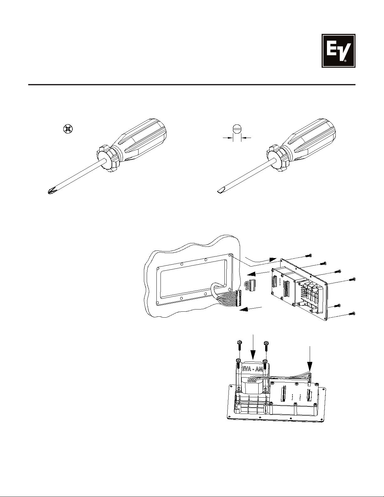
Tools Required:
1. #2 Phillips Screwdriver 2. 3/16” (5mm) Flat Blade Screwdriver
#2
3/16”
[5mm]
Instructions:
1. Remove the input panel by removing the eight screws securing it.
2. Carefully unplug the crossover cable from the 10-pin header.
3. Unplug and discard the 7-pin jumper connector at the far end of the circuit board.
Figure 1:
Remove panel, unplug
crossover cable and jumper
7-pin
10-pin
4. With the green circuit board on the
right, place the attenuation module
in the pocket provided for it on the
left with the lead wires from the
module pointing toward you.
5. Secure the EVA-AM mounting ears
to the four input panel bosses
with the four #10 screws provided.
Carefully tighten the screws evenly
in an X-cross pattern to avoid
warping the plastic input panel.
6. Plug in the 7-pin wiring harness
connector from the attenuation
module where the 7-pin jumper
was removed in step 3.
Figure 2:
Attach module and plug in
7-pin module connector
Page 2
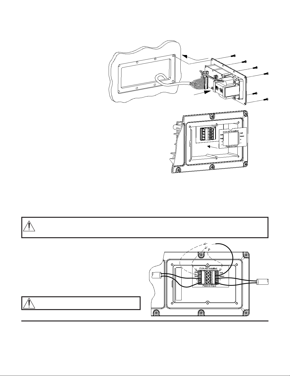
7. Reconnect the 10-pin connector from the crossover and reinstall the input panel.
EVA-AM must be on the enclosure center-line to maintain horizontal center of gravity.
Do not install input panel backwards!
Figure 3:
Reconnect crossover cable and
reinstall input panel
8. Apply the new label (supplied) over the input connectors.
Figure 4:
Apply new label over connectors
9. Connect one end of the blue wire (supplied) to the terminal marked “Select”. Set the
attenuation level for the module by connecting the other end of this wire to either the
-3 dB, -6 dB or -9 dB terminal, as determined by EVADA.
10. Connect the input lines to the module at the (+) and (-) terminals the same way you
would a standard non-attenuated EVA loudspeaker. The EVA-AM attenuates ONLY
the loudspeaker in which it is installed.
Important Note: Once an EVA-AM is installed, an attenuation level MUST be selected. (See step 9.)
If this wire is not connected, the entire loudspeaker in which the module is installed
WILL NOT FUNCTION!
Figure 5:
Connect input wires, set attenuation level, and
tighten unused screws
Tighten all unused connector screws to
prevent rattles!
Electro-Voice
12000 Portland Avenue South, Burnsville, MN 55337
Phone: 952/884-4051, Fax: 952/884-0043
www.electrovoice.com
© Bosch Communications Systems 06/2009
Part Number LIT000310 Rev 2
®
U.S.A. and Canada only. For customer orders, contact Customer Service at:
800/392-3497 Fax: 800/955-6831
Europe, Africa, and Middle East only. For customer orders, contact Customer Service at:
+ 49 9421-706 0 Fax: + 49 9421-706 265
Other Internatonal locations. For customer orders, Contact Customer Service at:
+ 1 952 884-4051 Fax: + 1 952 887-9212
For warranty repair or service information, contact the Service Repair department at:
800/685-2606
For technical assistance, contact Technical Support at: 866/78AUDIO
Specifications subject to change without notice.
 Loading...