

Electro-Voice EVA-2082S/906EVA-2082S/920EVA-2082S/126, EVA-2151D, EVA-2082S/1220, EVA-1151D User Manual
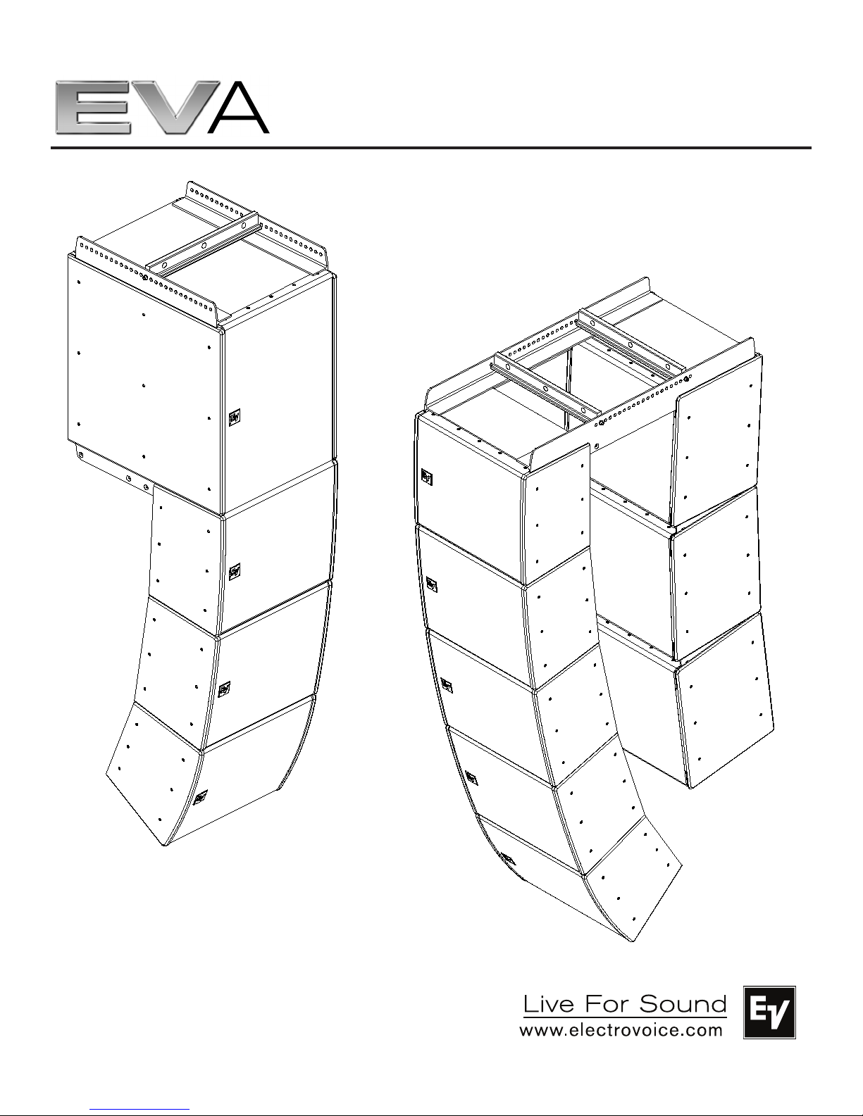
EVA Series
User Manual
EVA-2082S/906
EVA-2082S/920
EVA-2082S/126
EVA-2082S/1220
EVA-1151D
EVA-2151D
Electro-Voice EVA Series User Manual

Table of Contents
Rigging-Safety Warning ....................................................................................................................................................3
1.0 Introduction ..................................................................................................................................................................4
2.0 Tool List ......................................................................................................................................................................9
3.0 Designing an EVA Array ...........................................................................................................................................9
3.1 Applications for which EVA Arrays are Most Appropriate ...................................................................9
3.2 Typical Number of Arrays .............................................................................................................................9
3.3 Determining EVA Array Configuration with EVADATM (EVA Design Assistant) Software ...........10
3.4 Other Design Examples ............................................................................................................................ 16
3.41 Dealing with the Relatively High Low-Frequency Variation of Short Arrays .................. 16
3.42 A Five-Module Array Example .................................................................................................. 17
3.43 An Eight-Module Array Example .............................................................................................19
4.0 Preparing EVA Modules for Installation .............................................................................................................. 20
4.1 Recommended Preflight Procedures .................................................................................................... 20
4.2 Module Configuration ................................................................................................................................ 20
5.0 EVA Rigging System ............................................................................................................................................... 23
5.1 Overview of the EVA Flying System ....................................................................................................... 23
5.2 Deciding which Grid Configuration to Use with an EVA Array ........................................................ 24
5.21 Standard Grid with or without Second Spreader Bar ....................................................... 24
5.22 Extended Grid with or without Second Spreader Bar ....................................................... 25
5.23 Coupler Grid with or without Second Spreader Bar ......................................................... 26
5.24 Use of Two Standard Grids ...................................................................................................... 26
5.25 EVA-1151D Tie Plates .............................................................................................................. 27
5.3 Assembling and Flying an EVA Array .....................................................................................................28
6.0 Rigging-Strength Ratings and Safety Factors .................................................................................................29
6.1 Working-Load Limit and Safety Factor Definitions ............................................................................. 29
6.2 Structural-Rating Overview ...................................................................................................................... 30
6.3 Simplified Structural-Rating Guidelines ................................................................................................ 31
6.4 Special Rules when Flying EVA-2151D Subwoofer Modules ......................................................... 33
6.5 EVA Structural Rating Charts .................................................................................................................. 34
6.6 Electro-Voice Structural-Analysis Procedures .................................................................................... 36
7.0 Rigging Inspection and Precautions .................................................................................................................... 37
8.0 References ................................................................................................................................................................38
8.1 Rigging (Printed) ........................................................................................................................................ 38
8.2 Mechanical Engineering (Printed) .......................................................................................................... 38
8.3 Rigging (Websites) ....................................................................................................................................39
Notes .................................................................................................................................................................................. 39
2
Electro-Voice EVA Series User Manual

Rigging-Safety Warning
This document details general rigging practices appropriate to the entertainment industry, as they would
apply to the rigging of Electro-Voice EVA loudspeaker systems. It is intended to familiarize the reader
with standard rigging hardware and techniques for suspending EVA loudspeaker systems overhead. Only
persons with the knowledge of proper hardware and safe rigging techniques should attempt to suspend
any sound systems overhead. Prior to suspending any Electro-Voice EVA loudspeaker systems overhead,
it is essential that the user be familiar with the strength ratings, rigging techniques and special safety
considerations outlined in this manual. The rigging techniques and practices recommended in this manual
are, of necessity, in general terms to accommodate the many variations in loudspeaker arrays and rigging
configurations. As such, the user is expressly responsible for the safety of all specific EVA loud-
speaker array designs and rigging configurations as implemented in practice.
All the general rigging material contained in this manual is based on the best available engineering information concerning materials and practices, as commonly recognized in the United States, and is believed
to be accurate at the time of original printing. As such, the information may not be directly applicable in
other countries. Furthermore, the regulations and requirements governing rigging hardware and practices
may be superseded by local regulations. It is the responsibility of the user to ensure that any Electro-Voice
loudspeaker system is suspended overhead in accordance with all current federal, state and local regulations.
All specific material concerning the strength ratings, rigging techniques and safety considerations for
the EVA loudspeaker systems is based on the best available engineering information concerning the use
and limitations of the products. Electro-Voice continually engages in testing, research and development
of its loudspeaker products. As a result, the specifications are subject to change without notice. It is the
responsibility of the user to ensure that any Electro-Voice loudspeaker system is suspended overhead in
accordance with the strength ratings, rigging techniques and safety considerations given in this document and any manual update notices. All non-Electro-Voice associated hardware items necessary to rig a
complete EVA loudspeaker array (chain hoists, building or tower supports and miscellaneous mechanical
components) are the responsibility of others.
Electro-Voice
February 2011
Electro-Voice EVA Series User Manual
3

1.0 Introduction
The Electro-Voice EVA (Expandable Vertical Array) loudspeaker systems or line-array modules represent
an important step in line-array technology for small- and medium-scale fixed-installation sound reinforcement. The various models are designed to significantly simplify the physical assembly of a line array. Also,
arrays of EVA full-range modules are designed to be powered from one amplifier channel, the necessary
crossover and EQ functions accomplished with sophisticated passive networks. The individual loudspeaker drivers, Hydra™ plane-wave generators, acoustic waveguides, enclosures and rigging hardware were
all designed specifically for the EVA product line to not only achieve the highest acoustic output with the
highest fidelity but also produce a precise wavefront from each element to achieve state-of-the-art linearray performance. The EVA subwoofer modules are designed to compliment both the appearance and
performance of the EVA full-range modules in applications where additional low-frequency output is desired from a flown array. A brief description of the product line is included below. The various EVA series
modules are shown in Figure 1 with key dimensions and features.
Although the EVA full-range modules shown in Figure 1 are not physically symmetrical, their acoustic polar
responses are substantially symmetrical. Thus, stereo left and right arrays or left-center-right arrays may
be constructed with the modules in their normal right-side-up orientation as shown in Figure 1. However,
should the user desire, the module attachment points are such that mirror-image left-right arrays can be
made by constructing one array with its modules turned upside down with respect to the views of
Figure 1.
Each EVA full-range module contains two separate, vertically stacked line-array elements splayed within
the module at one-half the included vertical angle of the vertically trapezoidal enclosure. The two elements of each module consist of two vertically stacked EVS2008 8-inch (203 mm) LF drivers (one per
element) and two pairs of DH2005 1.25-inch-diaphragm (32 mm) HF drivers (one pair per element).
Each HF driver pair is mounted on a Hydra™ plane-wave generator, the two of which are vertically stacked
and splayed with their respective elements. Each module effectively functions as one self-contained zone
within an array, with the added benefit of the internal shading network being able to attenuate either the
upper or lower HF driver pair by 3 dB to help smooth transition between zones when needed.
EVA-2082S/906: two-way, LF/HF line-array module with a 90° horizontal x 6° vertical coverage pattern
(for long throws) and passive crossover/HF-shading/EQ network. The enclosure is trapezoidal in the vertical plane with a 6° total included angle. The two line-array elements contained in the module are vertically
splayed by 3°.
EVA-2082S/920: two-way, LF/HF line-array module with a 90° horizontal x 20° vertical coverage pattern (for short throws) and passive crossover/HF-shading/EQ network. The enclosure is trapezoidal in
the vertical plane with a 20° total included angle. The two line-array elements contained in the module are
vertically splayed by 10°.
EVA-2082S/126: two-way, LF/HF line-array module with a 120° horizontal x 6° vertical coverage pattern
(for long throws) and passive crossover/HF-shading/EQ network. The enclosure is trapezoidal in the vertical plane with a 6° total included angle. The two line-array elements contained in the module are vertically
splayed by 3°.
4
Electro-Voice EVA Series User Manual

1.0 Introduction (cont’)
EVA-2082S/1220: two-way, LF/HF line-array module with a 120° horizontal x 20° vertical coverage pattern (for short throws) and passive crossover/HF-shading/EQ network. The enclosure is trapezoidal in
the vertical plane with a 20° total included angle. The two line-array elements contained in the module are
vertically splayed by 10°.
EVA-AM: this optional attenuation module mounts on the inside of an EVA-2082S input panel, and attenuates the entire module by 3, 6 or 9 dB. The nominal impedance of an EVA-2082S module is 16 ohms.
Up to six paralleled EVA-2082S modules can be driven from a single amplifier channel capable of driving
a 2.7-ohm nominal impedance (16 ohms ÷ 6 modules = 2.7 ohms).
Up to eight paralleled EVA-2082S modules can be driven from a single amplifier channel capable of driving a 2.3-ohm nominal impedance if at least two of the modules have the optional EVA-AM attenuation
modules installed.
Both single-15-inch and dual-15-inch EVA subwoofer modules are available. Both use the DVX3159A
15-inch (381 mm) woofer designed specifically for subwoofer duty, providing reliable low-frequency performance at high SPL levels with low distortion and solid impact. Subwoofer modules do not have in-
ternal passive crossovers and require an active crossover and dedicated amplifier channel(s)
for proper operation.
EVA-1151D: compact single-15-inch subwoofer module capable of being flown either above or behind
an EVA full-range array. This is a rectangular unit with special tie plates that allow for assembly with either
zero or five degrees of splay between modules. It may also be used in a stand-alone subwoofer array or
ground-stacked.
EVA-2151D: large rectangular dual-15-inch subwoofer module designed for use only at the top of an
EVA full-range array. It may also be used in a stand-alone subwoofer array or ground-stacked.
The standard EVA indoor versions are finished in tough EVCoat™. In addition, all EVA modules (except
EVA-2151D) are available in two levels of weather resistance. The FG versions, e.g., EVA-2082/906FGB, are designed for full weather exposure and feature a fiberglass-finished enclosure, stainless-steel
three-layer hydrophobic grille and the CDG dual-gland-nut input-panel cover. The PI versions, e.g., EVA2082S/906-PI, are rated for indirect outdoor exposure only in protected areas, such as under a roof
overhang, and feature a stainless-steel three-layer hydrophobic grille and CDG dual-gland-nut input-panel
cover on an enclosure finished in standard EVCoat. External fasteners on all EVA systems are stainless
steel.
All EVA modules are available in black or white and are supplied with the hardware necessary to fasten
one module to another and two cosmetic end caps, which give the finished array a smooth and uncluttered appearance. (The end caps on FG fiberglass versions are also finished in fiberglass.) Black is indicated by BLK or B at the very end of the complete model number and white is indicated by WHT or W at
the very end of the complete model number, e.g., EVA-2082S/906-BLK and EVA-2082S/906-PIB.
Electro-Voice EVA Series User Manual 5

1.0 Introduction (cont’)
EVA-SG2-BLK and EVA-SG2-WHT: standard grids for typical down angles with small arrays, or top
and bottom suspension for extreme down angles in large arrays of EVA-1151D subwoofer and/or EVA2082S full-range modules. NOT FOR USE WITH EVA-2151D subwoofer.
EVA-EG2-BLK and EVA-EG2-WHT: extended grids for extreme down angles in small to medium arrays
and typical down angles in large arrays. This is the only grid for flying EVA-2151D subwoofers.
EVA-CG: coupler grid for flying EVA-1151D subwoofer modules behind an EVA full-range array.
The three different grid options (EVA-SG2, EVA-EG2 and EVA-CG) are sold separately. Consult
EVADA software for proper grid selection.
NOTE: SERIES 2 GRIDS EVASG2, EVAEG2 ARE REQUIRED TO FLY EVA SUB
WOOFER MODULES. OLDER GRIDS EVASG, EVAEG ARE FOR FLYING EVA FULL
RANGE MODULES ONLY.
EVA-GXB-BLK and EVA-GXB-WHT: optional second spreader bars for EVA grids, to be used when
two-point front-to-back hangs are desired. Note: the need to maintain sufficient pressure on the forward
rigging point will limit the amount of down angle available with the standard EVA grids (EVA-SG or EVASG2) in this configuration.
CDG: optional dual-gland-nut input-panel cover to protect the input connections from water. Note that
this cover is supplied with the weather-resistant versions of EVA modules.
CSG: optional single-gland-nut input-panel cover to protect the input connections from water.
CDNL4: optional input-panel cover equipped with dual Neutrik Speakon® NL4 connectors, providing a
quick-disconnect alternative to the standard Phoenix screw-terminal input connectors.
6
Electro-Voice EVA Series User Manual
1.0 Introduction (cont’)
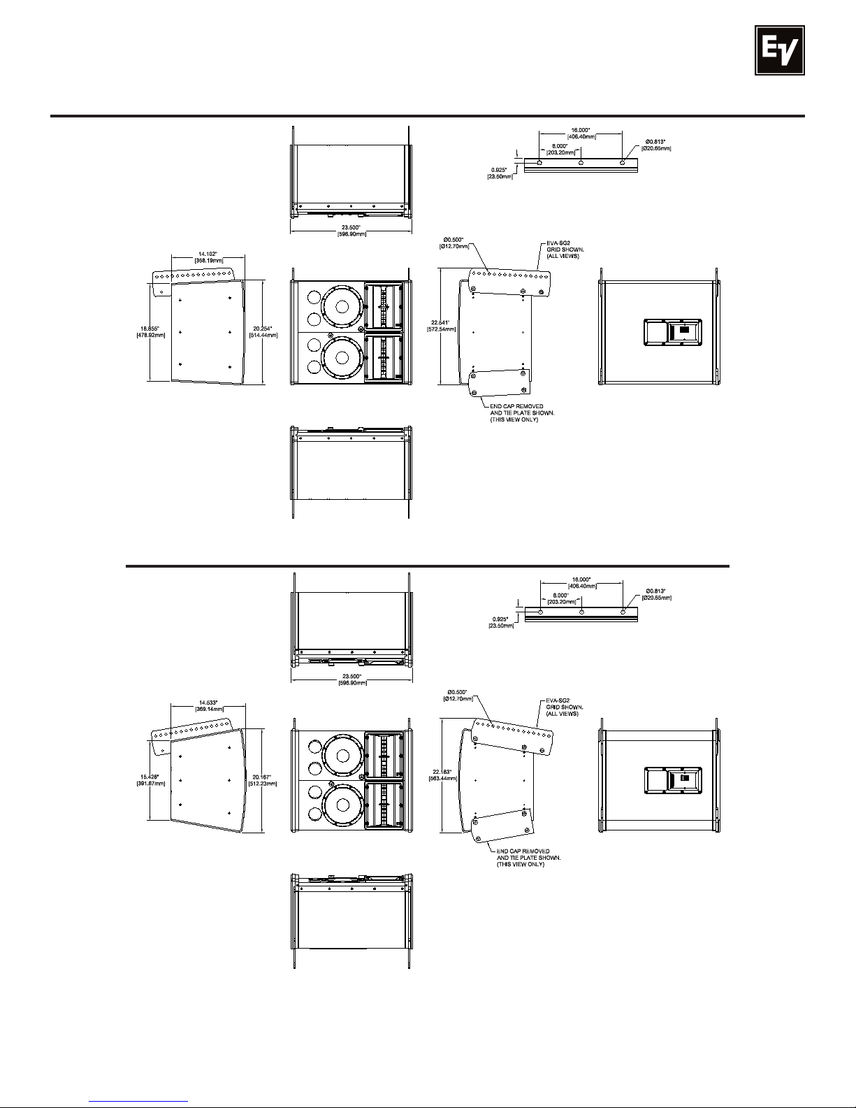
Top View
Spreader Bar
Attach Holes
Right View
EVA-2082S/906 or EVA-2082S/126 dimensioned views
Front View
Bottom View
Top View
Rear View
Left View
Figure 1a:
Spreader Bar
Attach Holes
Right View
EVA-2082S/920 or EVA-2082S/1220 dimensioned views
Electro-Voice EVA Series User Manual
Front View
Bottom View
Rear View
Left View
Figure 1b:
7
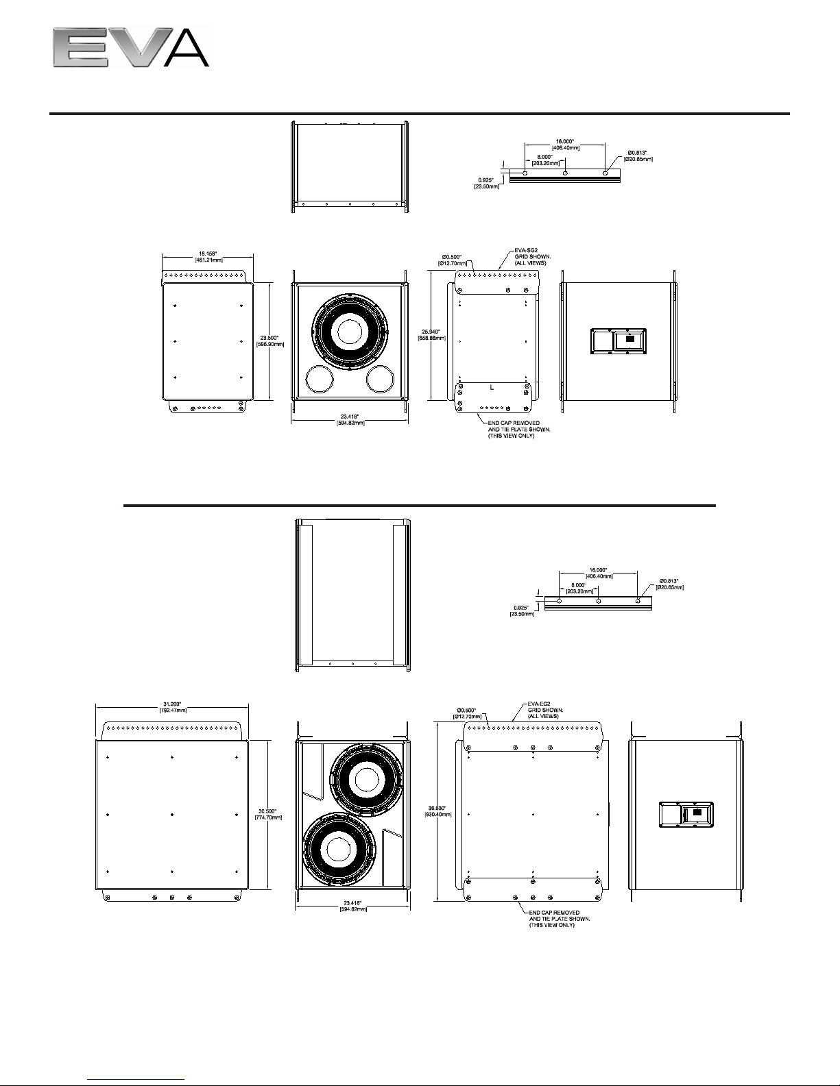
1.0 Introduction (cont’)
Spreader Bar
Attach Holes
Top View
Right View
Front View
Left View
Figure 1c:
EVA-1151D dimensioned views
Top View
Rear View
Spreader Bar
Attach Holes
Right View
Front View
Left View
Figure 1d:
EVA-2151D dimensioned views
Rear View
Electro-Voice EVA Series User Manual8
2.0 Tool List
Listed below are the tools required to assemble an EVA array:
1. Phillips #2 screwdriver (for attaching cosmetic end panels).
2. 6-mm Allen (hex) wrench (for attaching tie plates and assembling grids).
3. 3/16-inch flat-blade screwdriver (for attaching signal wires to input-panel connectors).
3.0 Designing an EVA Array
NOTE: WHEN FLOWN IN THE SAME COLUMN WITH FULLRANGE MODULES FROM AN EVA
SG2 OR EVAEG2 GRID, SUBWOOFERS MUST ALWAYS BE AT THE TOP OF THE ARRAY.
3.1 Applications for Which EVA Arrays Are Most Appropriate
The total included vertical angles of the EVA modules in side view (6° for long throw and 20° for short
throw) were determined after making many array simulations with the EVA Design Assistant (EVADA™)
software (described in some detail below). Optimum maximum distance for uniform front-to-back coverage is 100 ft ±25 ft.
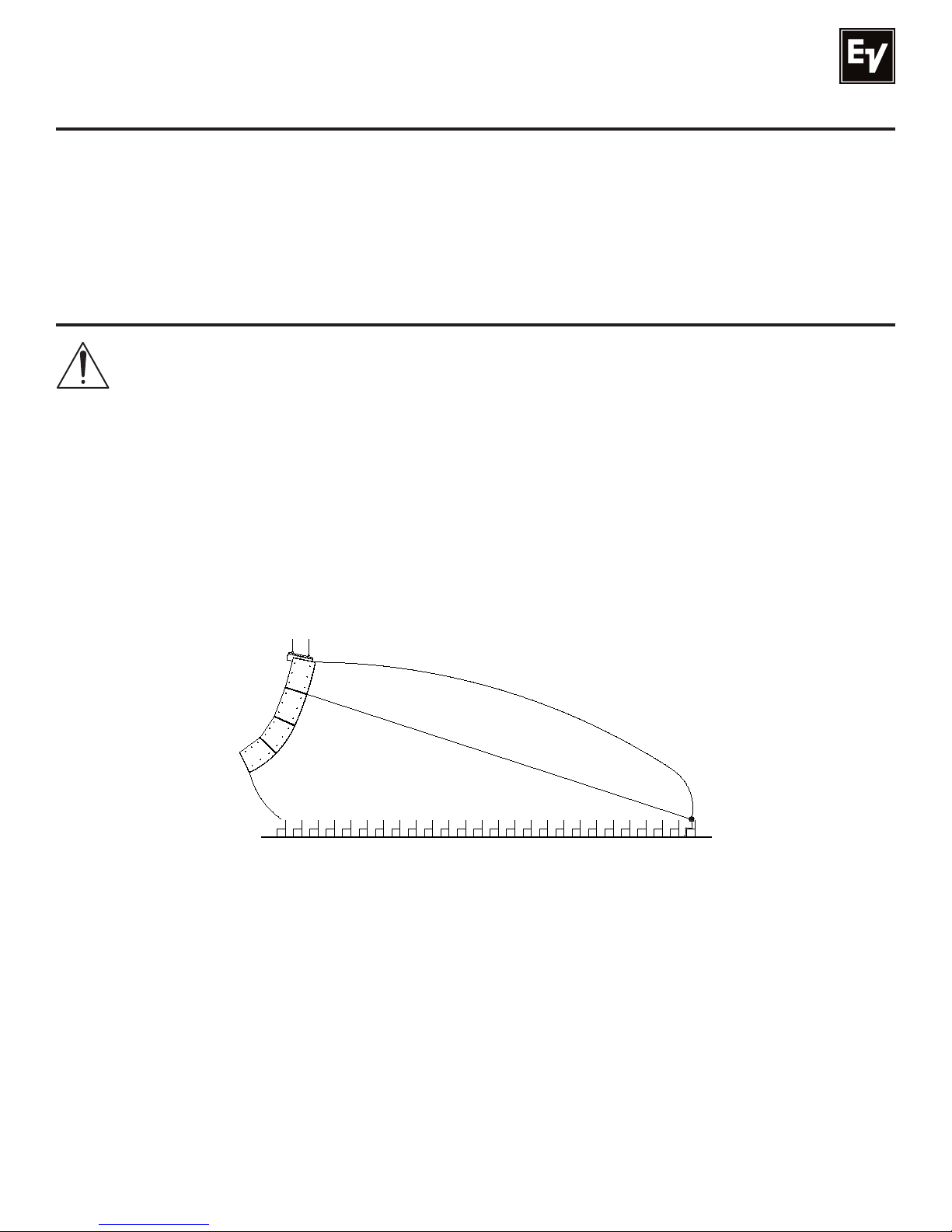
In side view, a quick rule of thumb for aiming a three- or four-box array in a venue with a flat floor is to have
a line running through the intersection of the top two modules intersect the head of the person in the last
row. This situation is shown in Figure 2.
Figure 2:
Rule-of-thumb for aiming three- and four-module EVA arrays
3.2 Typical Number of Arrays
Line-array systems usually consist of vertical columns of multiple independent line-array elements. The
most common implementation is probably a stereo sound reinforcement system with two columns (left
and right). Additional columns are sometimes added to cover different seating sections of a venue, e.g.,
seating areas that wrap around the side or back of a stage. An additional column is also used in left-center-right configurations, with the center channel for speech. In some venues, where stereo is not desired,
good coverage can be obtained with a single array. A variation of such a monaural system is the exploded
array, where two or more widely spaced (on the order of 10 ft or more) arrays are used to provide the
horizontal coverage required. Also, a large number of arrays may be used in distributed systems, such as
in an arena.
Electro-Voice EVA Series User Manual 9
3.0 Designing an EVA Array (cont’)
3.3 Determining EVA Array Configuration with EVADA™ (EVA Design Assistant) Software
EVADA™ is Excel-spreadsheet-based software for determining optimum array configurations for a given
venue and trim heights. The latest version of EVADA is downloadable from the Electro-Voice Web site
(www.electrovoice.com).
Briefly, one models the room along the horizontal aiming axis of the array, then builds the array of longand/or short-throw modules that produces the most even coverage front to back. (As described above,
EVA modules come in two horizontal coverage angles, 90° and 120°. Following industry convention, these
angles are defined where output is 6 dB down from the maximum [usually on axis] output. Choose the
horizontal angle that provides good coverage of the audience in plan view but minimizes energy directed
on reflective wall surfaces, which energizes the room and lowers the intelligibility of the sound system.)
EVADA displays coverage in three frequency bands. The default bandwidth is one-third octave. The default frequencies are 500 Hz, 3,000 Hz and 8,000 Hz. 3,000 Hz is very important for voice intelligibility.
8,000 Hz is important for “sparkle.” 500 Hz (and below) is important for maintaining a good spectral balance throughout the venue. Longer arrays provide low-frequency uniformity closer to the mid- and highfrequency performance of the array. These effects can be easily seen in EVADA. In addition, the frequencies and bandwidths can be modified by the designer.
EVADA includes an extensive help file but the following overview will provide a good introduction.
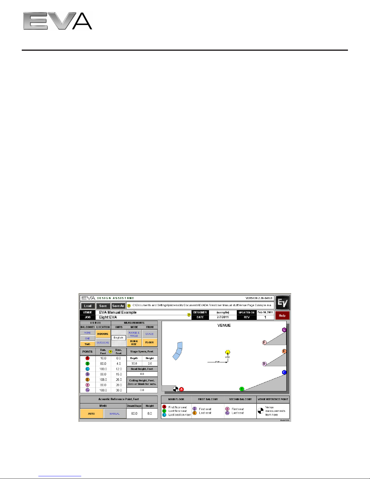
Figure 3 shows the Venue tab of the EVADA spreadsheet, where the room information is entered, including dimensions, head height, stage specs (optional) and the so-called “acoustic reference point.” This is
the point in the venue where EVADA makes its sound-pressure level (SPL) calculations and is AUTO set
to head height at point “B”. Clicking on the MANUAL tab allows a different point to be entered.
EVADATM Venue tab, where room information is entered
10
Figure 3:
Electro-Voice EVA Series User Manual

3.0 Designing an EVA Array (cont’)
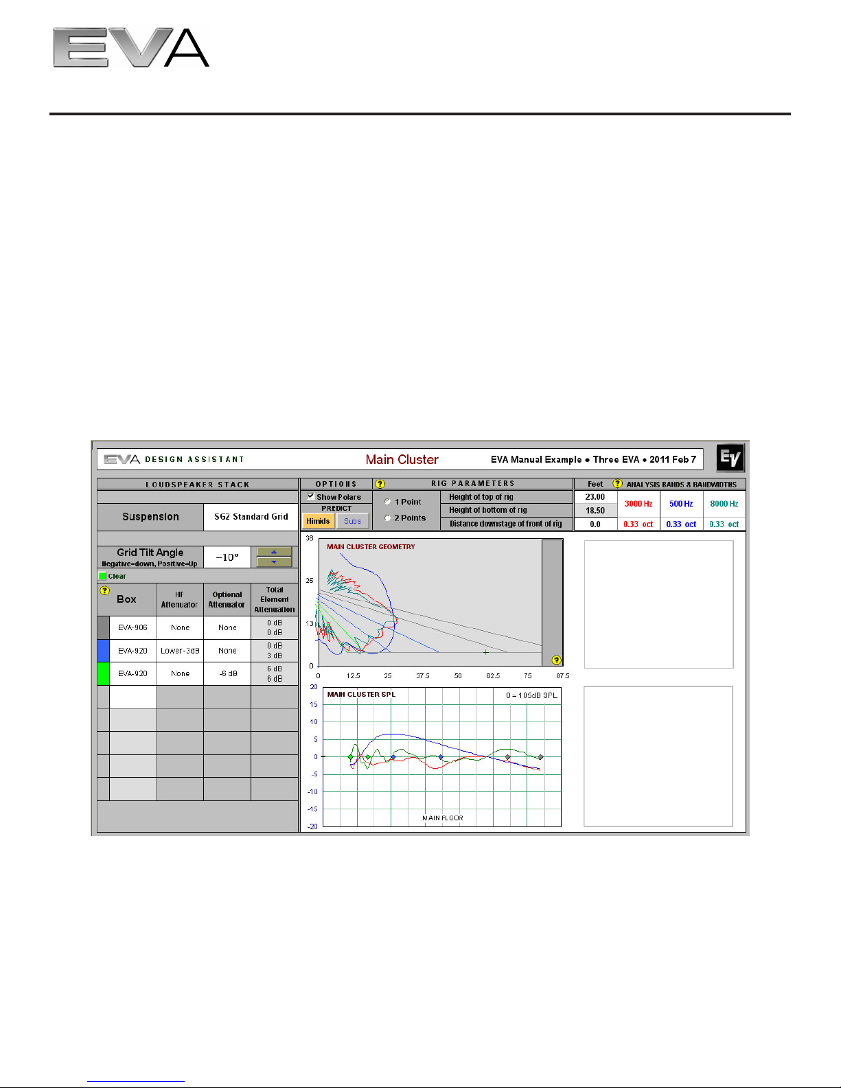
Figure 4 shows the EVADA Main tab, where the array is built and its performance evaluated in the three
frequency bands mentioned above. This tab is full of information and things to enter:
1. In the top middle of the view is where the number of suspension points (one or two, front to
back), array trim height and distance downstage from front of rig are chosen. Regarding trim
height, be sure to allow for the height of the lifting mechanism(s) and attachment points.
2. At the top right of the view is where the three frequency bands and their bandwidths are
shown. The default bandwidth is 0.33 octave and the default frequencies are 3,000 Hz,
500 Hz and 8,000 Hz. These can be changed by the user.
3. The Loudspeaker Stack column and table at the upper left allows the user to (1) choose the
grid (click on the default grid cell to access a selection menu), (2) adjust the grid tilt angle,
and (3) select a combination of EVA modules to array. The HF Attenuator column contains
cells which show the effect of the internal 3-dB high-frequency attenuator (high-frequency
shading): no attenuation or attenuation of either the upper or lower high-frequency driver
pair. The Optional Attenuator column contains cells which show the effect of the optional
EVA-AM attenuator module: 0 dB (not installed), or 3 dB, 6 dB or 9 dB (installed).
4. Once the elements of items 1 and 3 are complete, clicking on the yellow Update Prediction
button will calculate array performance. This button appears in the Main Cluster geometry
view immediately under the words “MAIN CLUSTER GEOMETRY”. The module vertical
aiming angles are also displayed, with a different colored, slightly splayed line pair for each
module (as noted in Section 1.0, there are two line-array elements in each EVA module, vertically splayed by 3° or 10°, depending on model). If the Show Polars box is checked under
Options, the vertical polar responses of the array are also shown in this area, in the three
frequency bands and bandwidths chosen. The acoustic reference point described earlier is
the small plus sign shown near the rear of the seating area.
5. The most important predicted information is shown in the Main Cluster SPL graph below
the Main Cluster Geometry view. This shows the predicted coverage uniformity front (left)
to back (right) in dB, where 0 dB is the value shown in the upper right-hand corner of the
Main Cluster SPL view. (In Figure 4, this value is 105 dB SPL.) Note that SPL prediction is
a complex function of the array maximum output versus frequency, the spectral distribution
and peak-to-average ratio of the program material, the dynamic peak capability of the power
amplifiers, and room acoustics. However, the EVADA calculated SPL value has been found
to be close to the peak indications, e.g., peak pointer readings, on a sound level meter with
C or F (flat) weighting in its fast averaging mode under the following conditions: (1) typical
broadband contemporary music program, (2) two arrays operating in a reverberant environment and (3) using the power amplifiers recommended in the engineering data sheets
(available at www.electrovoice.com). (A one-array design would reduce the predicted SPL
by 3 dB.)
Electro-Voice EVA Series User Manual
11
3.0 Designing an EVA Array (cont’)
Producing the most uniform front-to-back coverage is an iterative process. In general, it will be found that:
1. The top-most module will be aimed above the last-row heads. This may appear to aim array output at the back wall, which if reflective could produce audible delayed signals in the
front of the room. However, reference to the 3,000- and 8,000-Hz vertical polar responses
shows that maximum array output is aimed at the rear-most heads, not at the rear wall.
2. The lower modules will be attenuated. This is required because the lower modules are so
much closer to the seats they cover than are the upper modules.
Coverage uniformity of ±3 dB front to back is a good goal for mid and high frequencies. At 500 Hz and
below, such uniformity may not be attainable, particularly for short arrays (see additional comments in Section 3.41).
EVADATM Main tab, where the array is built and performance is displayed in three frequency bands
Figure 4:
Electro-Voice EVA Series User Manual12
 Loading...